1. Computer Aided Design
What is CAD?
Computer-Aided Design (CAD) refers to the use of computer software to create, modify, analyze, and optimize designs. CAD is widely used in engineering, architecture, manufacturing, and product design.
It allows designers to create both 2D drawings and 3D models with precision and efficiency. It allows developers to manage code versions, work on branches, and merge changes seamlessly.
Key features of Git include:
2D – Used for creating technical drawings, schematics, and plans.
3D – Used for designing three-dimensional objects and assemblies.
Parametric CAD – Uses constraints and relationships between elements to control design modifications.
Modeling – Allows flexible modifications without predefined constraints.
For the final project
3D modeling for mechanical design.
Simulation & analysis to test structural integrity.
Rendering & animation to visualize the tray’s movement.
3D printing for prototyping and and circuit box.
I used a combination of 2D and 3D software to model designs for exploring the tools.
For 2D vector graphics, I work with CorelDRAW to create precise shapes, outlines, and technical drawings. I have chosen this tool due to its ease usability.
I also used GIMP for raster editing when I need to manipulate images or textures for concept visuals.
My modeling process typically begins with planning and sketching out concepts, either on paper or digitally. I then use CorelDRAW to create accurate vector drawings or technical layouts.
In Fusion 360 and SolidWorks, I begin by creating sketches within the software, and then use tools like extrude, revolve, sweep, loft, and fillet to build 3D geometry.
I apply parametric constraints and dimensions to keep the design flexible and accurate.
This workflow allows me to move efficiently from concept to prototype while ensuring visual quality, technical accuracy, and manufacturability.
Navigate the links below to access the design
I used different tool to design different parts in order to explore more tools and how to use them.
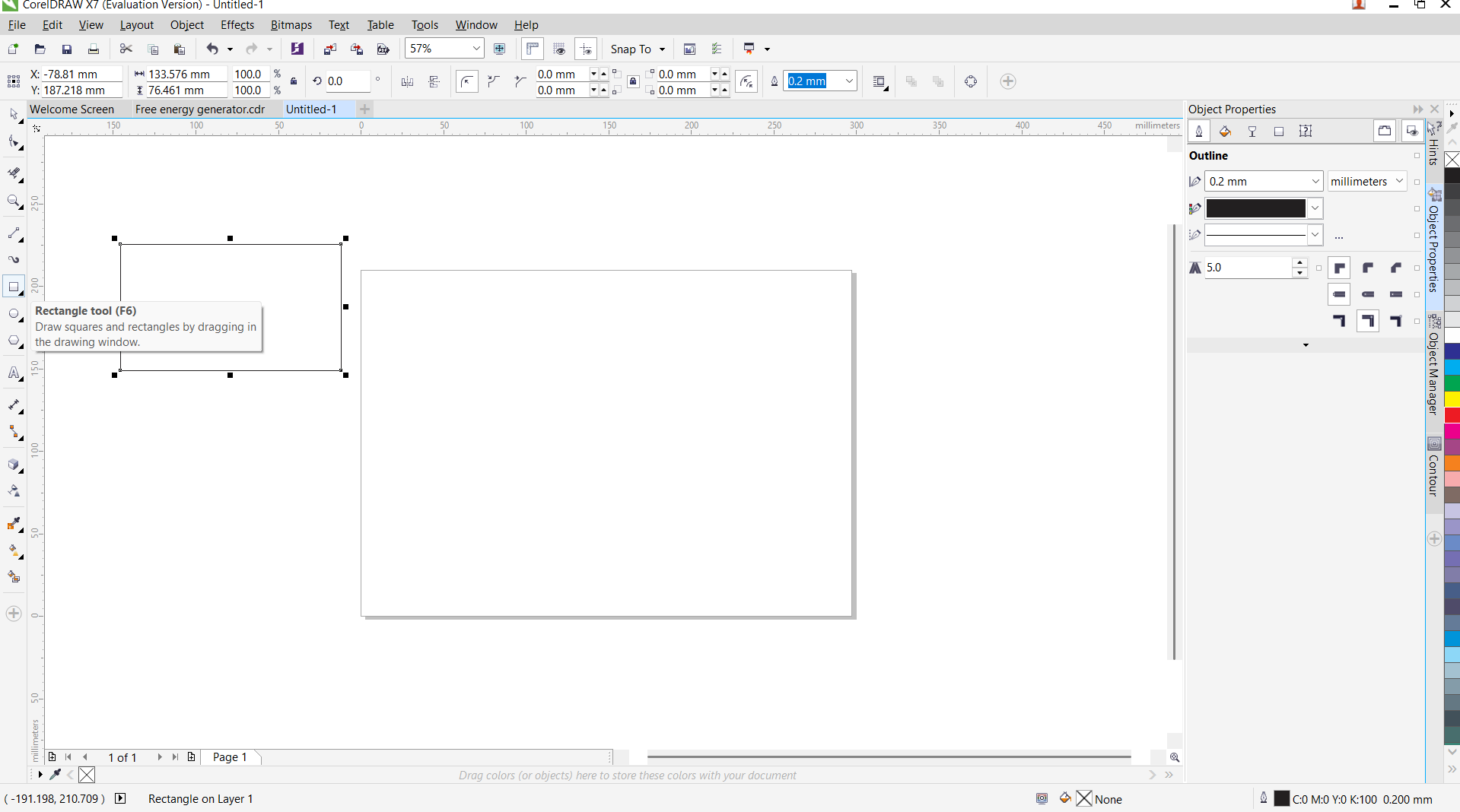
Firstly I opend CorelDraw software to start design.
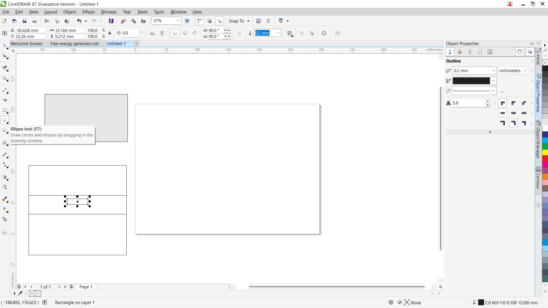
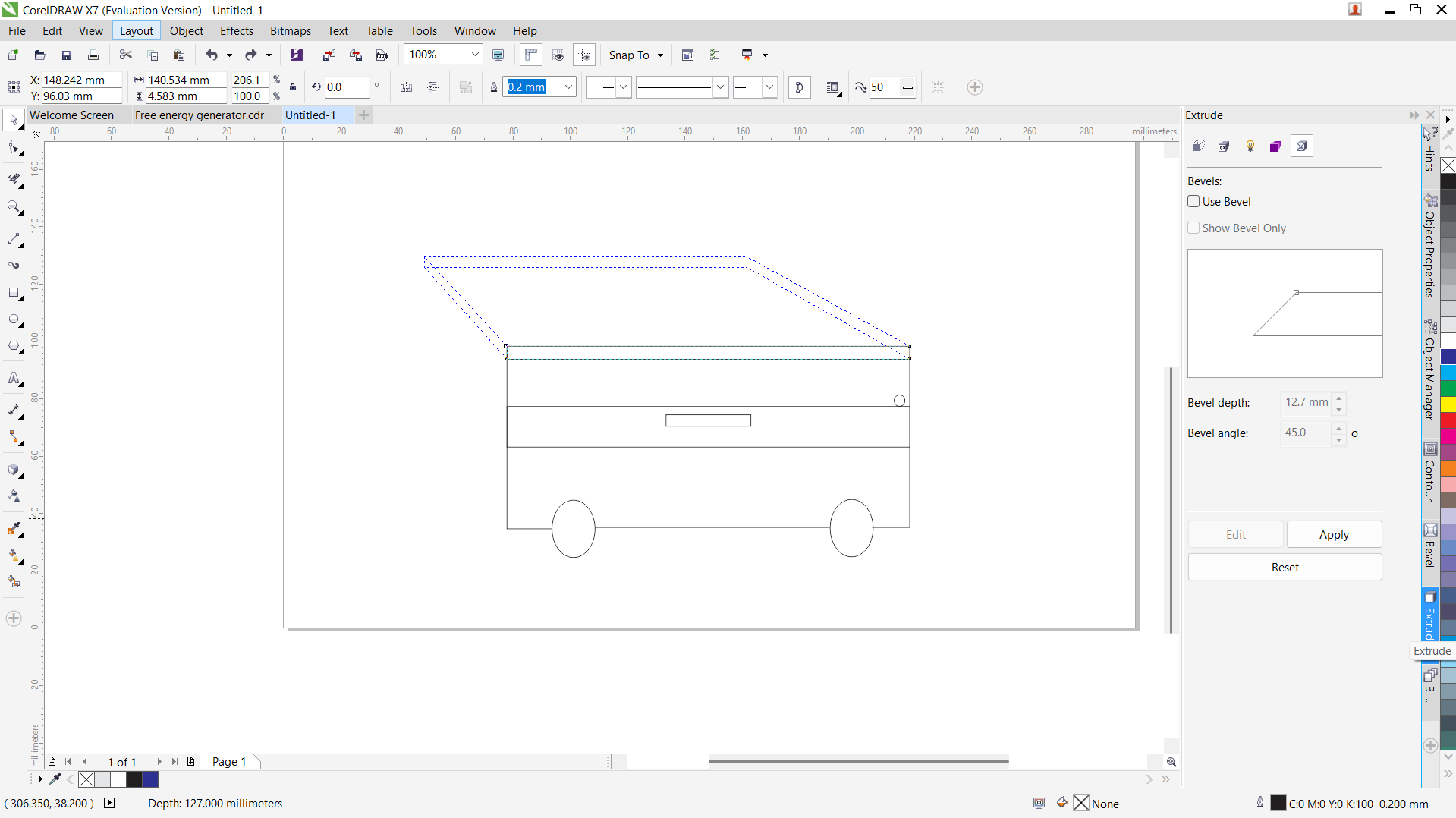
I used rectangle tool to create tray, frame, shelf and the eclips to create wheels.
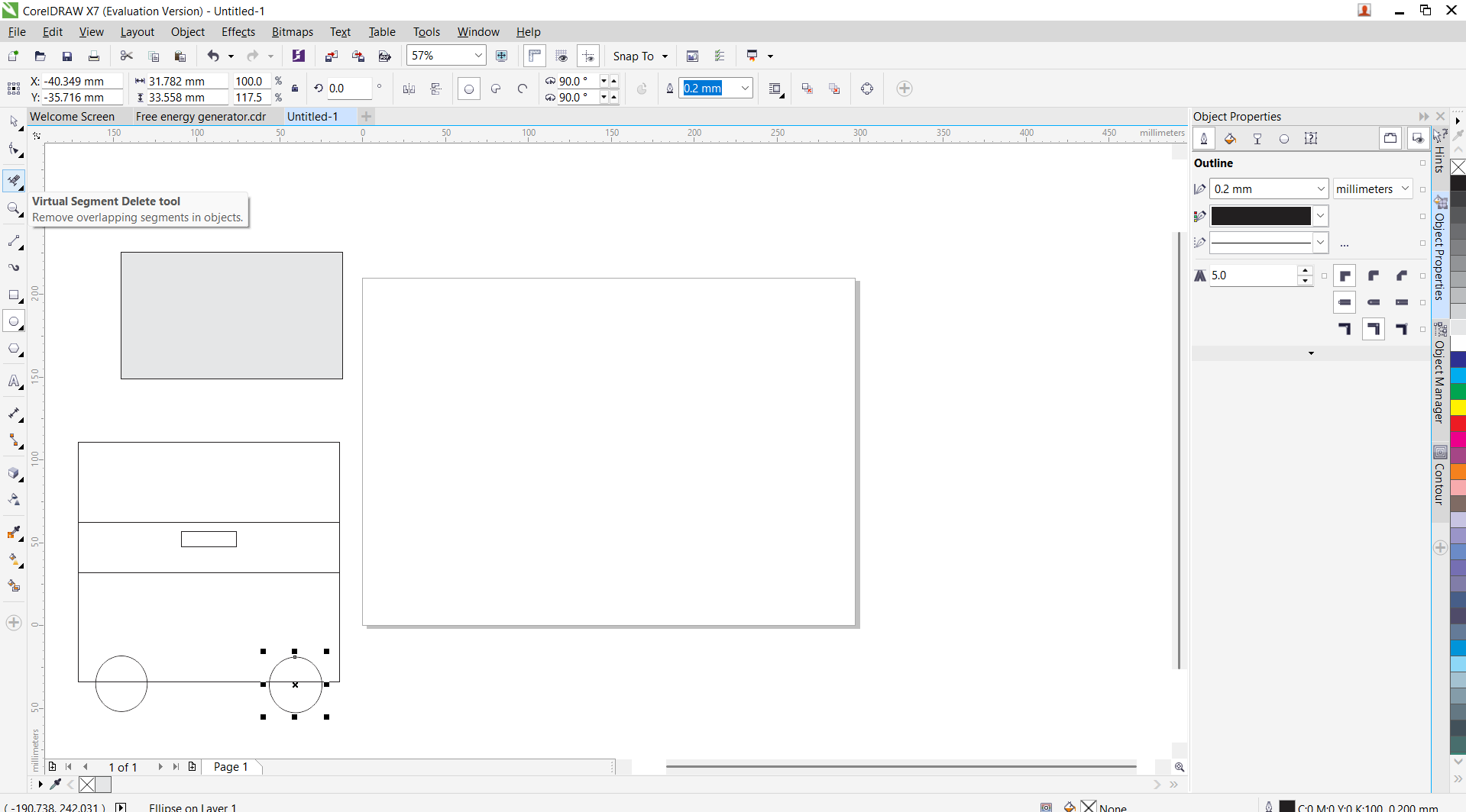
I used eclips tool to create wheels and the virtual segment delete tool, and combined in one object.
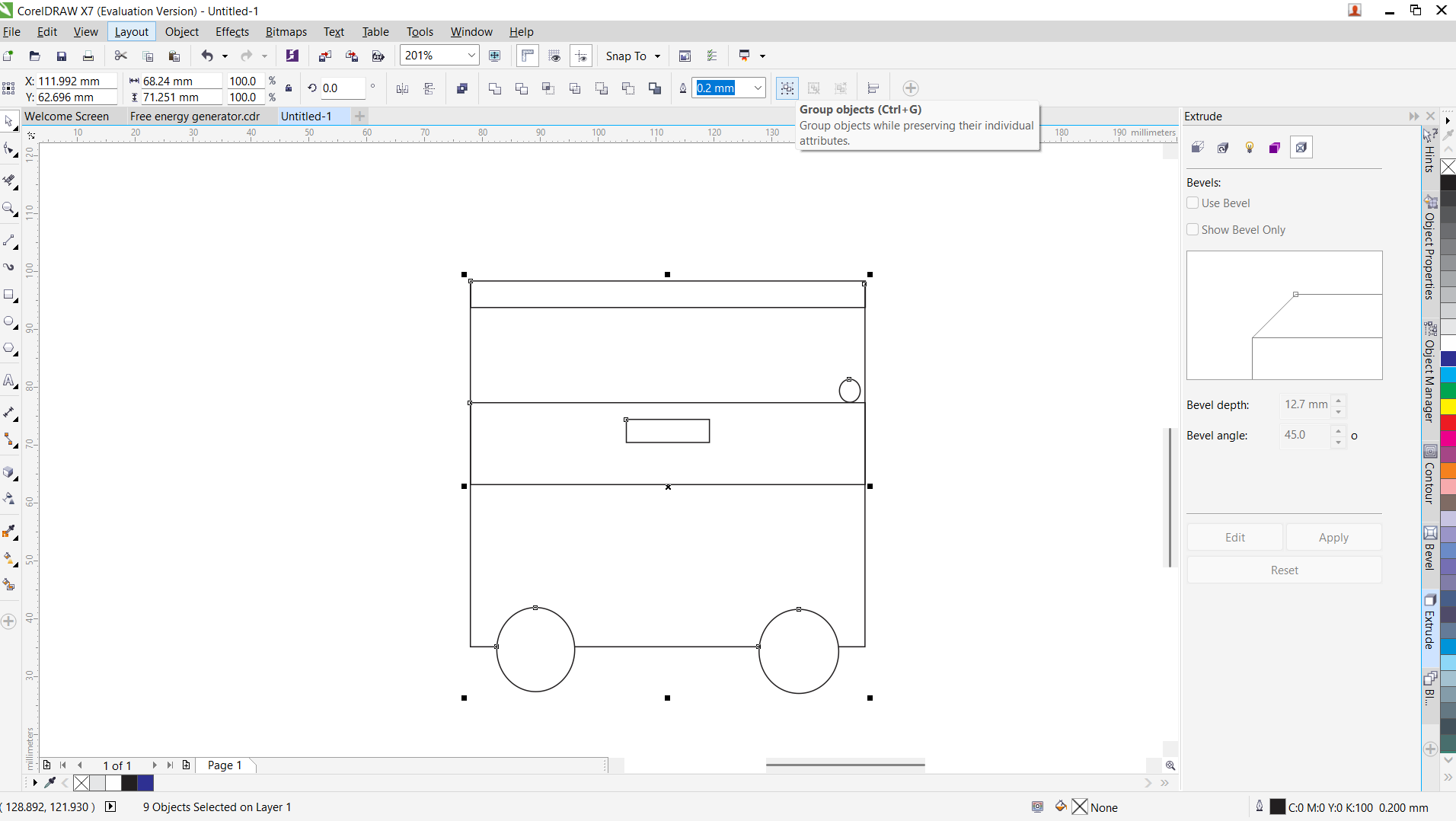
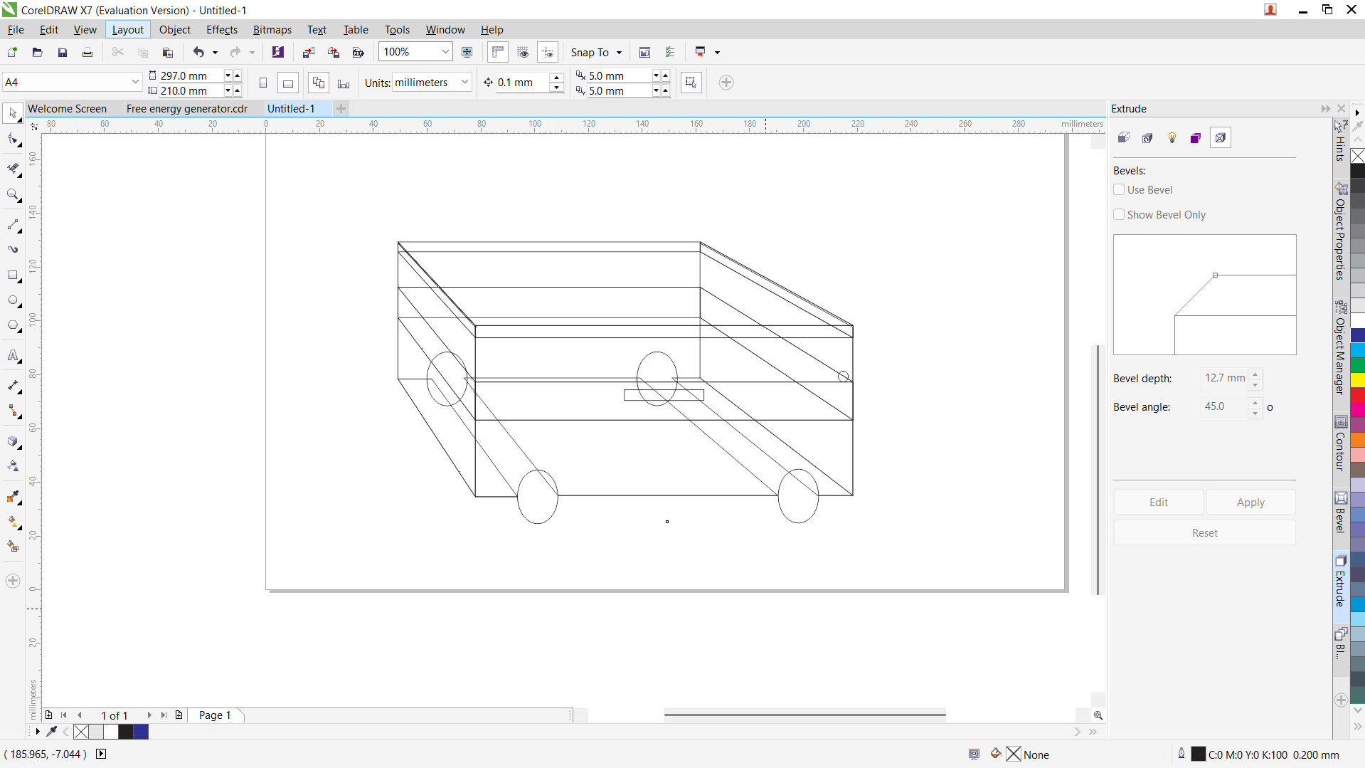
I used extrude tool to covert to 3D dsign.
Coloring the model
I selected each object to give it a colour. The recent colours used appears at the bottom of the workspace. It is found under emboss tool.

Converted object into bitmap top roduce raster image.
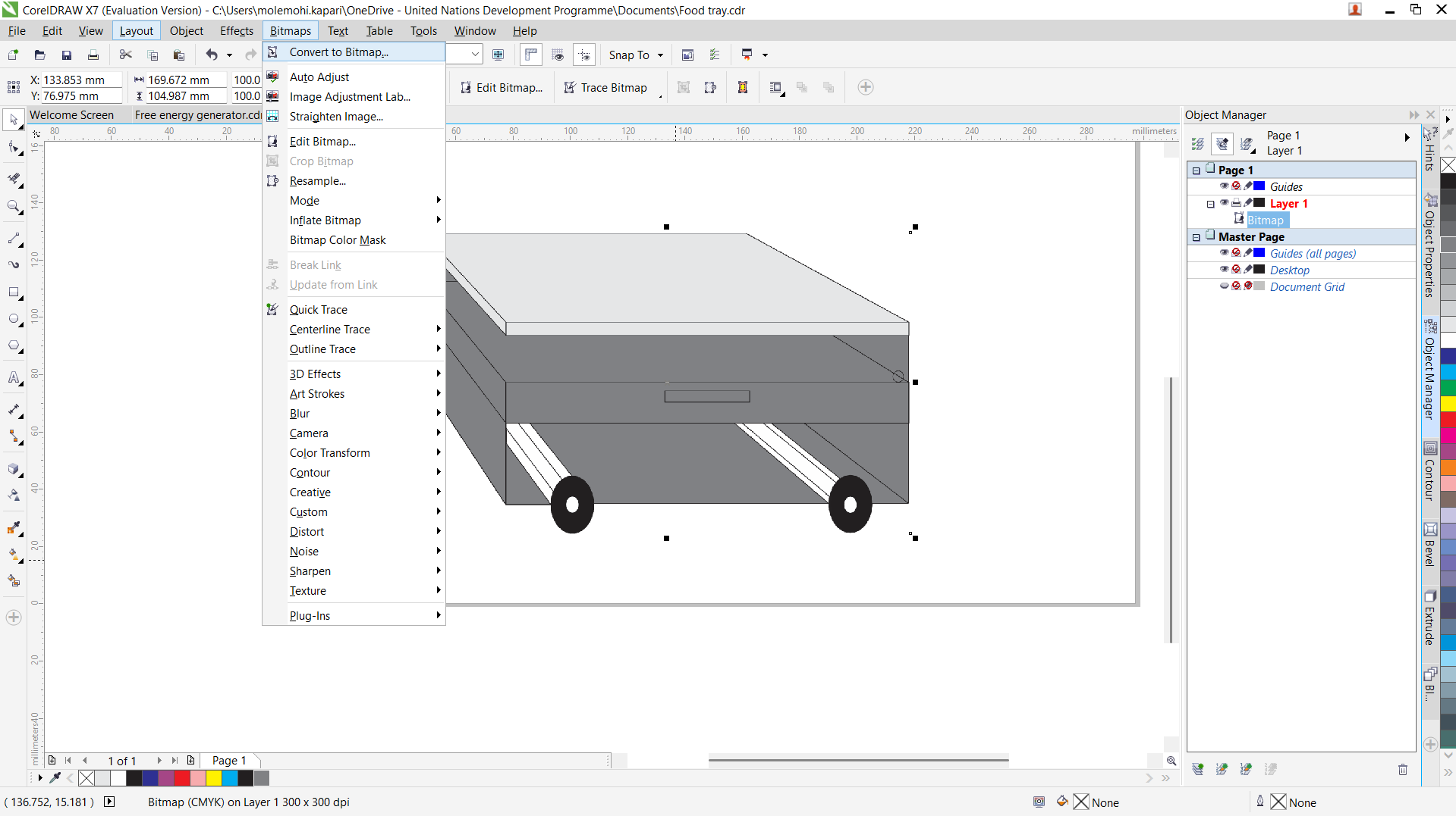
Used different styles to apply on bitmap image like plastic, stone, planes
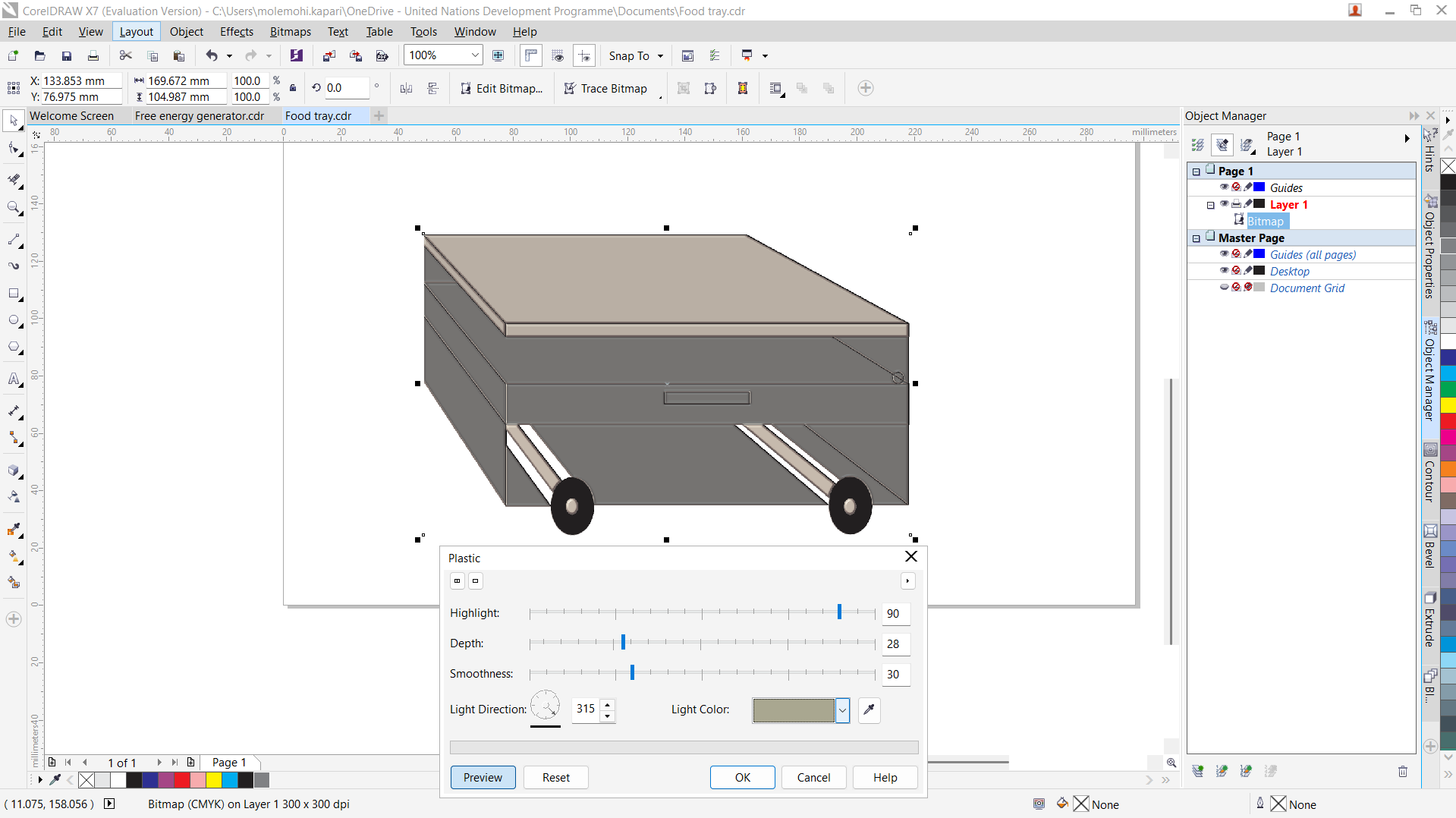
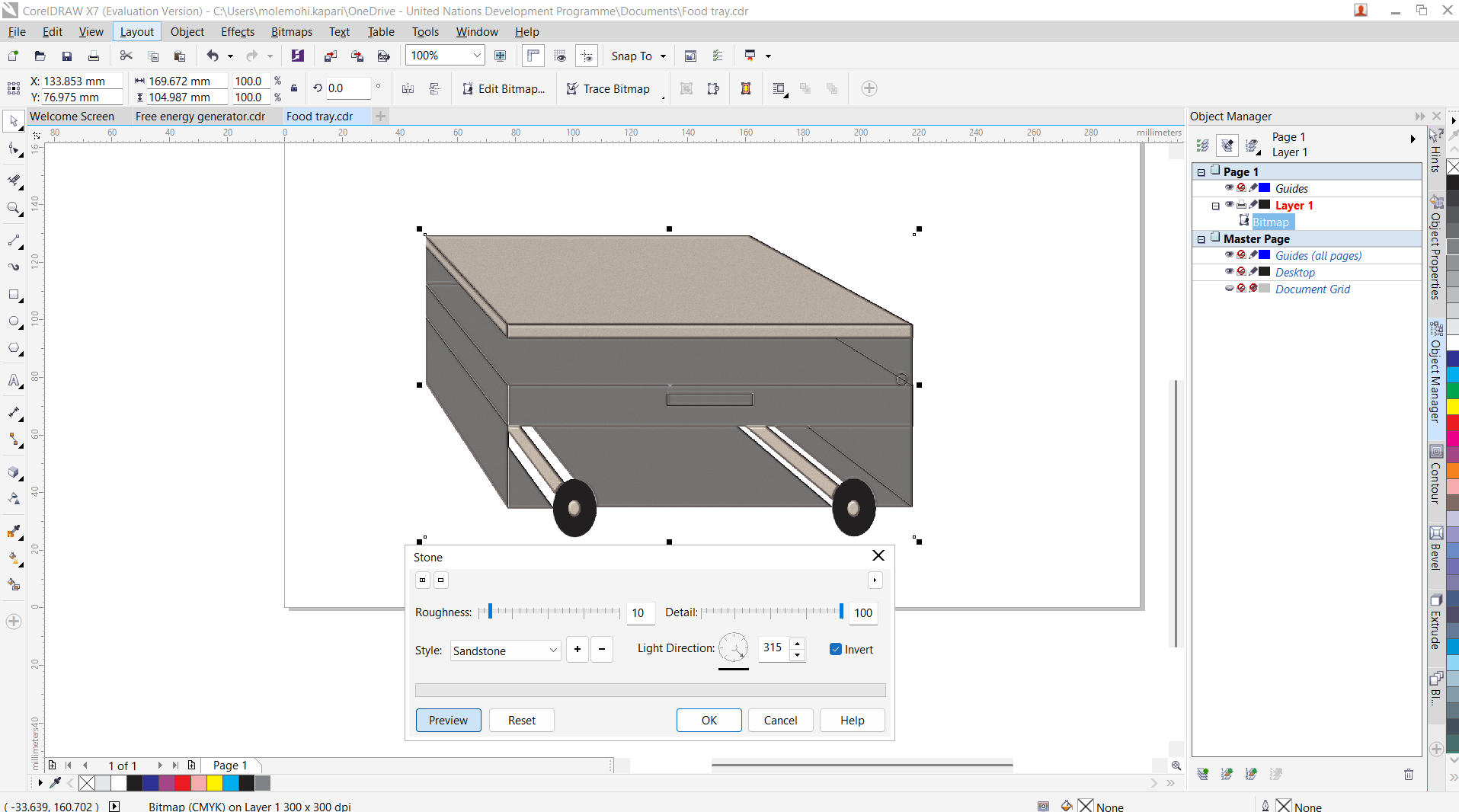
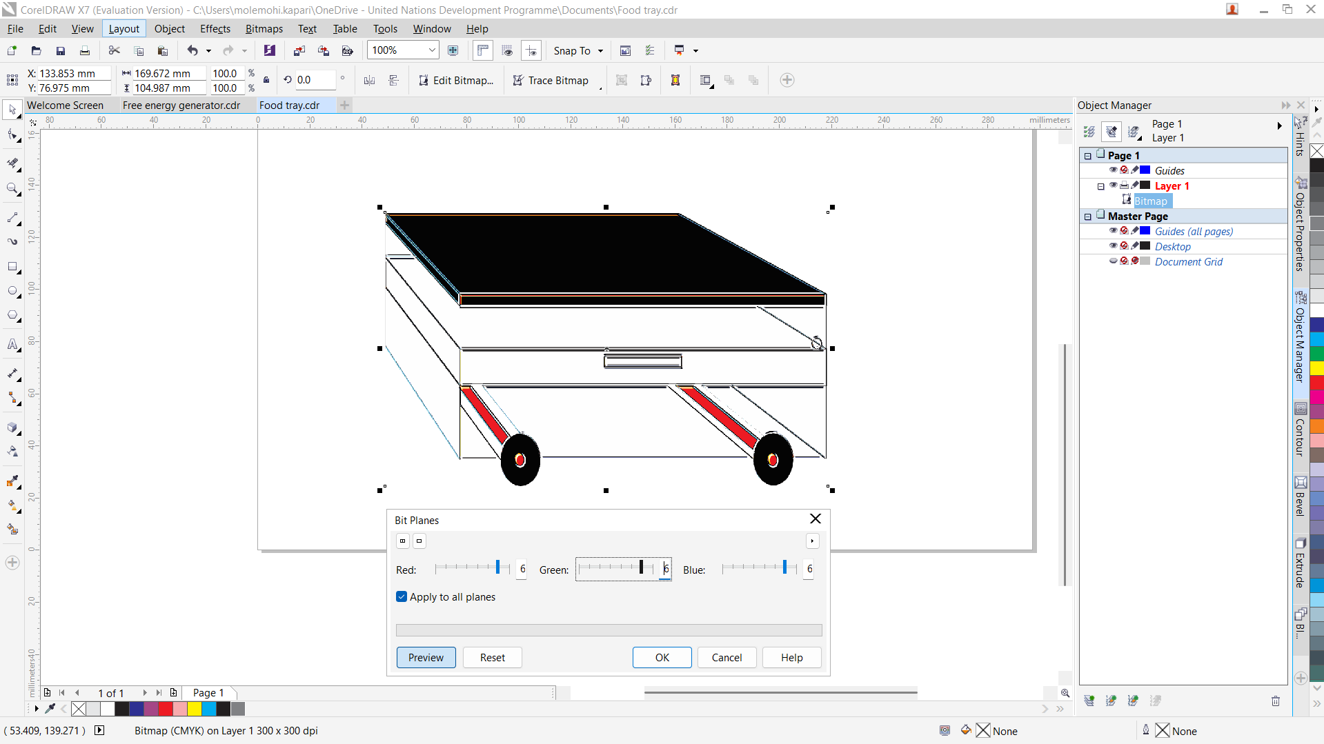
This is the final product.
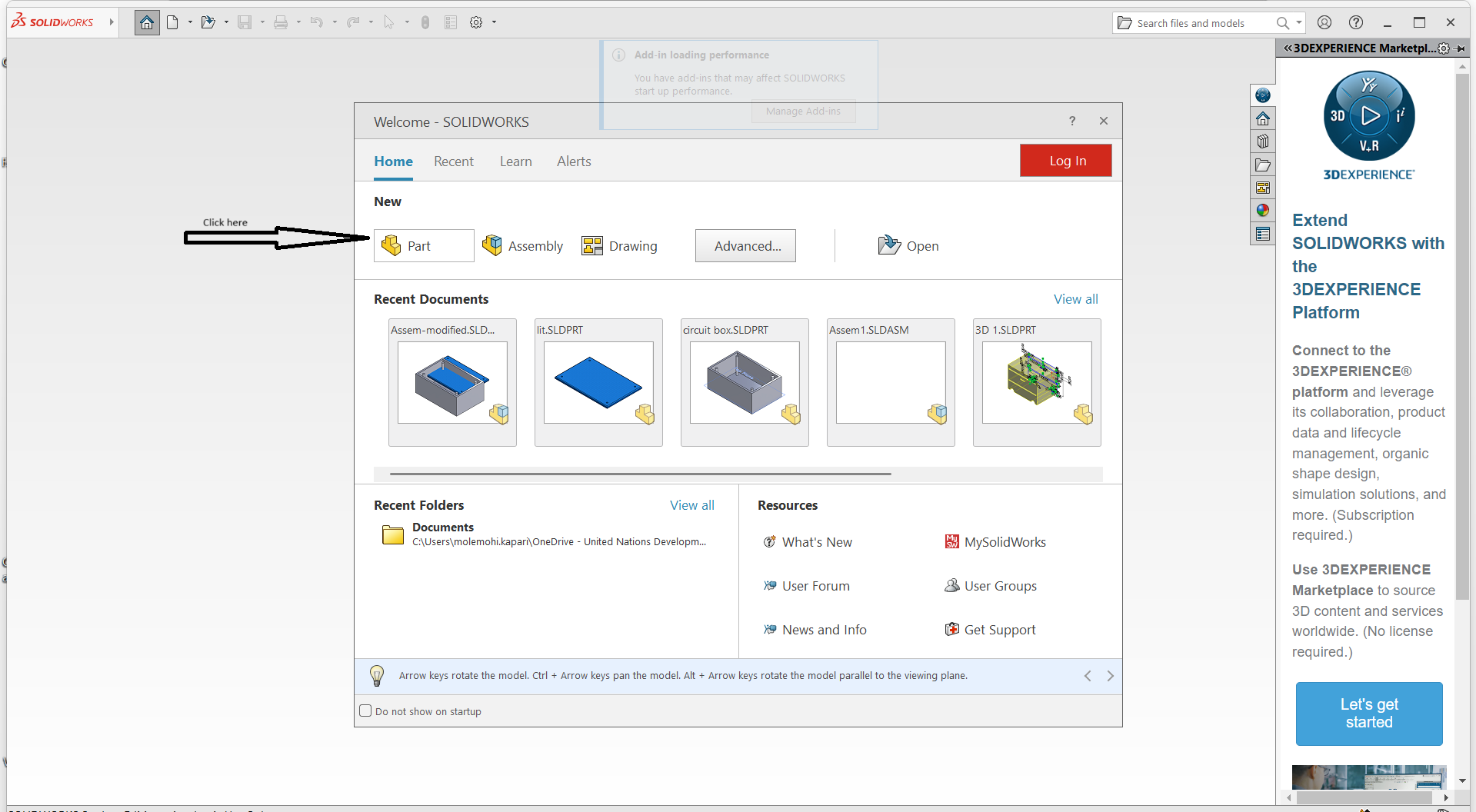
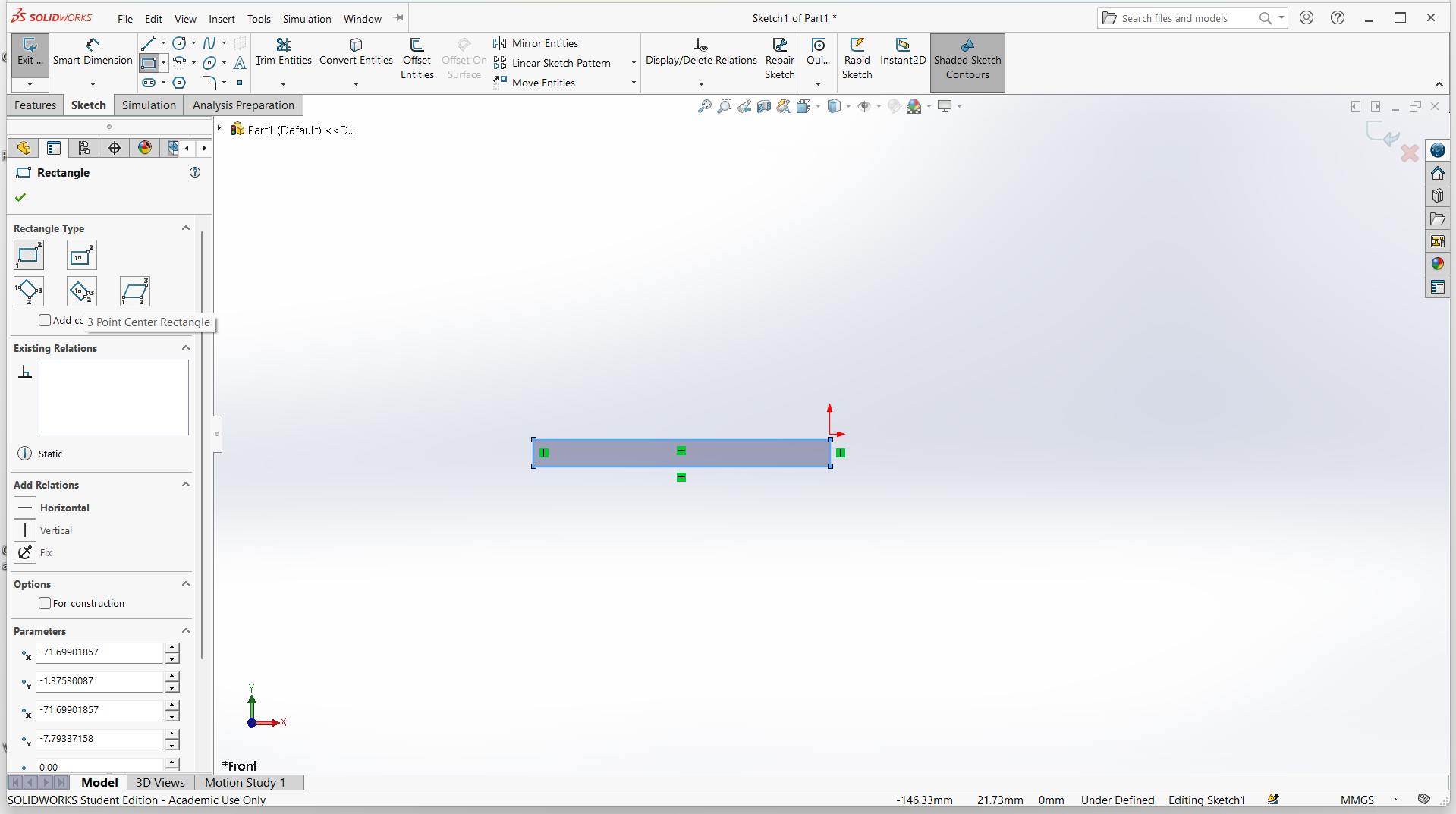
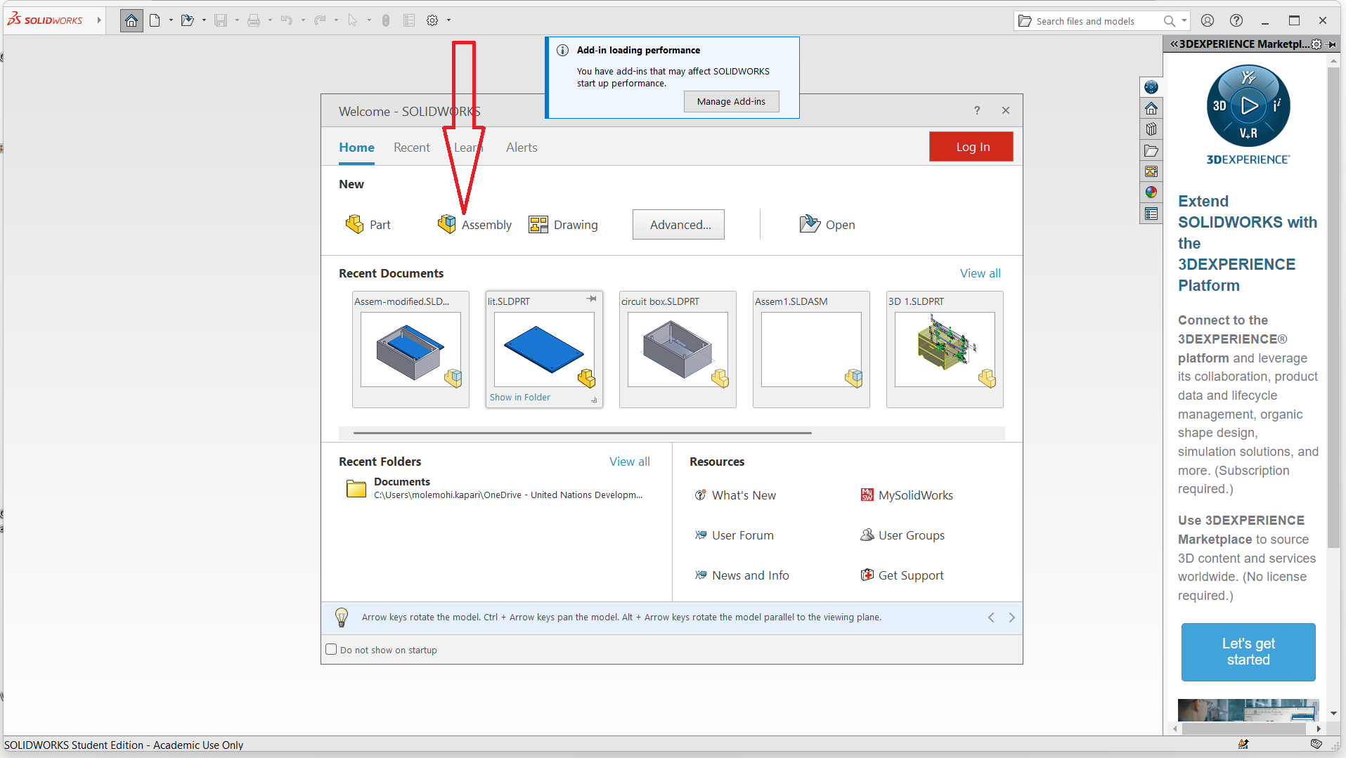
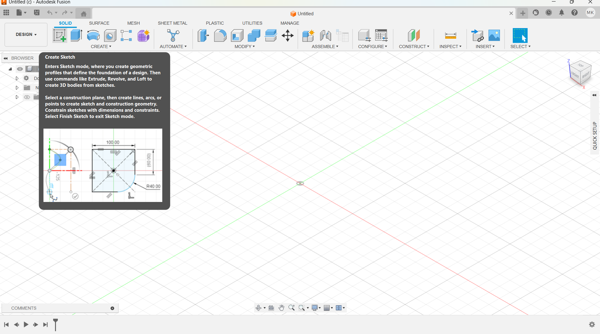
After opening this is the interface where to create a project, then I selected part on the menu to create project parts.
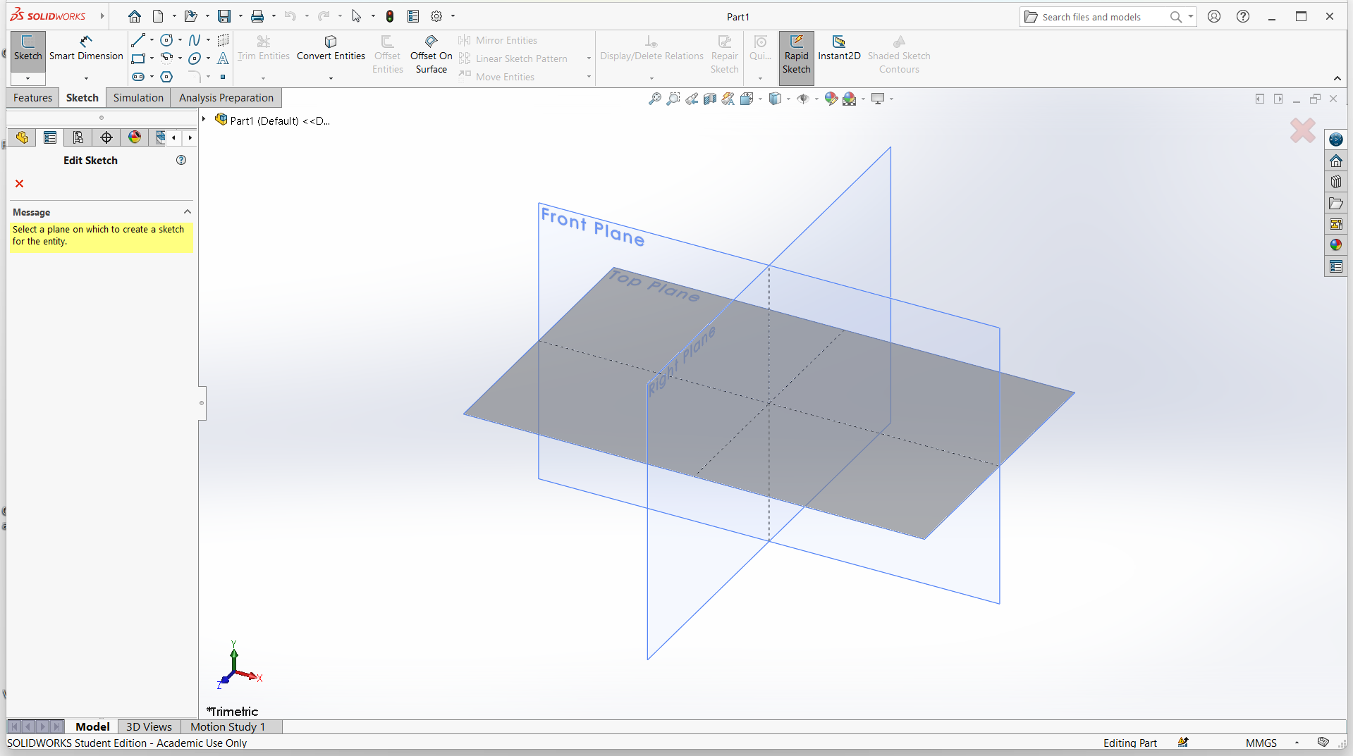
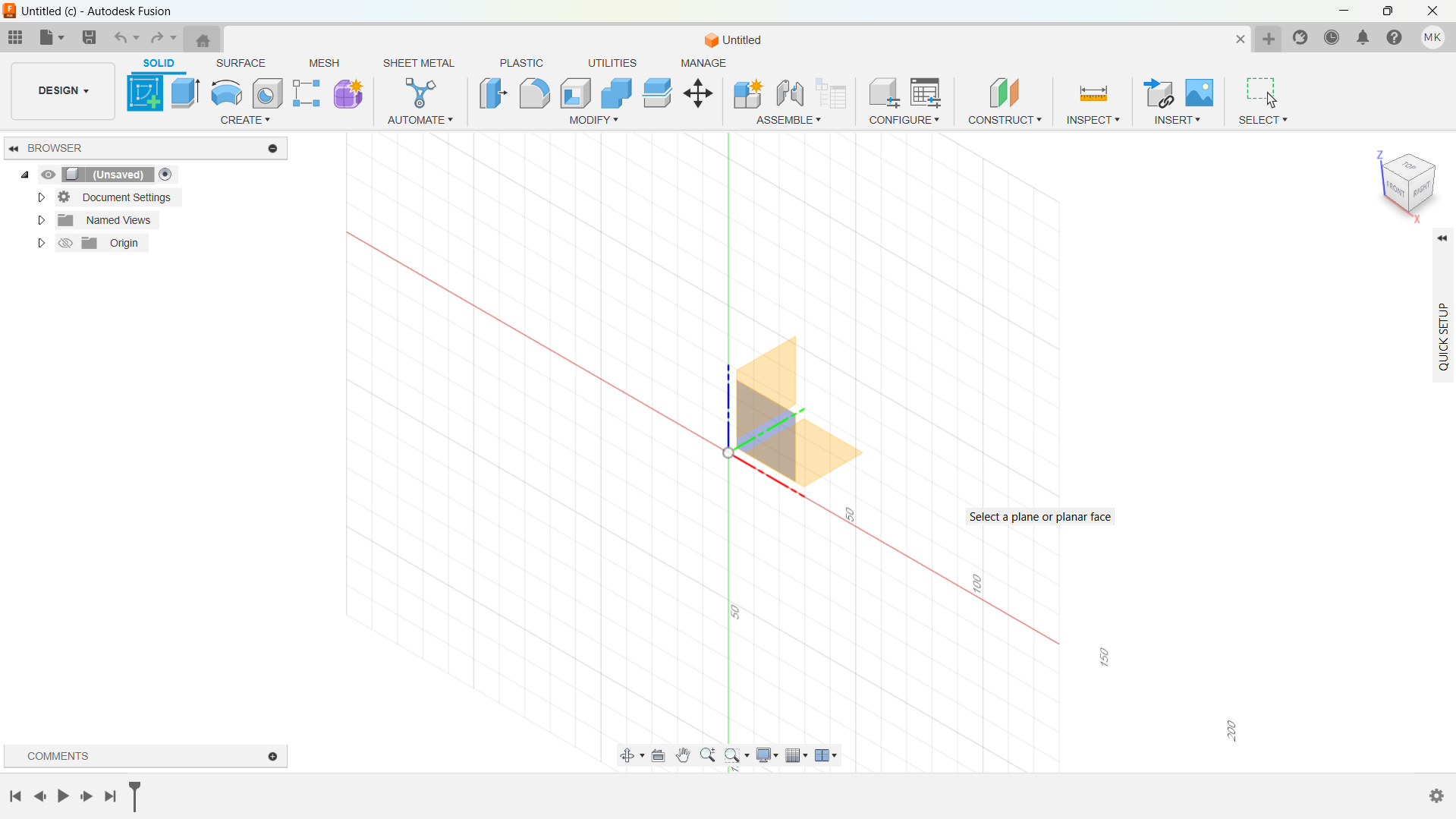
Select the plane where to create a new sketch to model the project. The sketch contains the content of the project.
I used top plane.
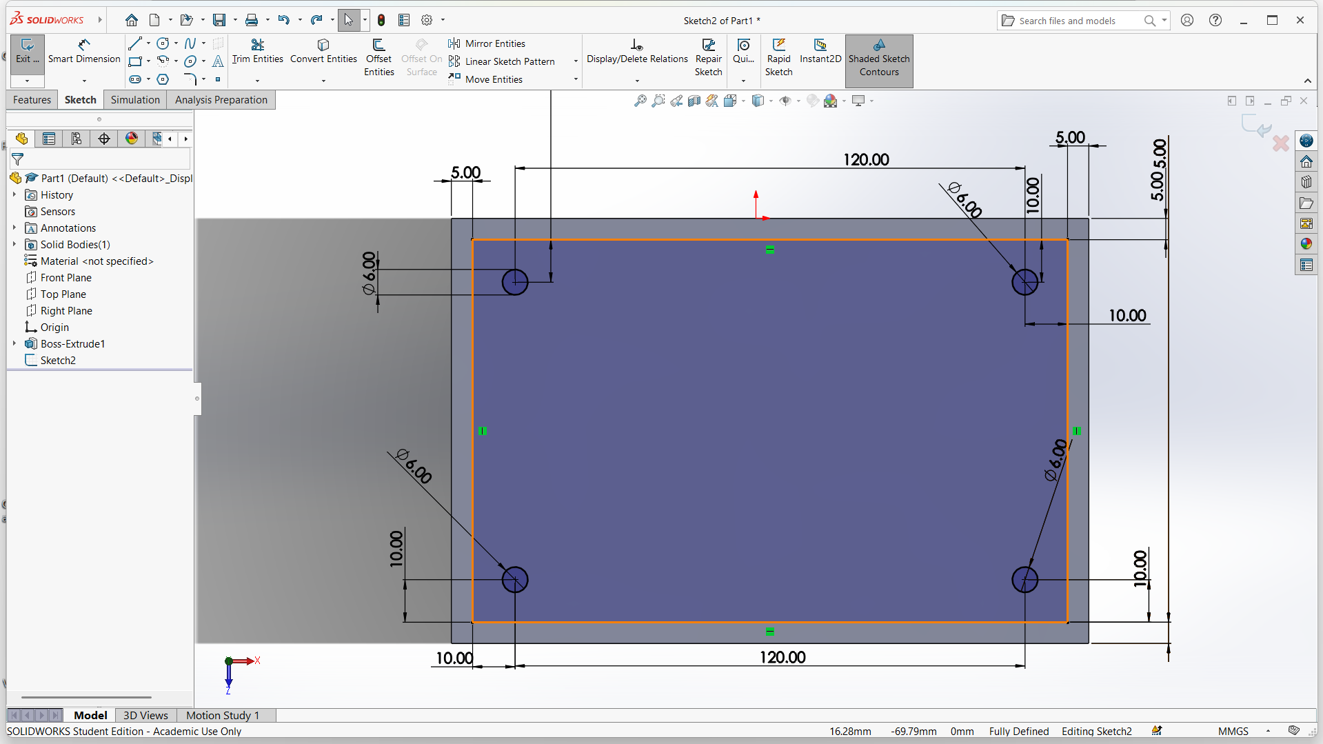
I created a rectangle using rectangle tool on the menu. I also used smart dimansion to give my shape pricise measurements.
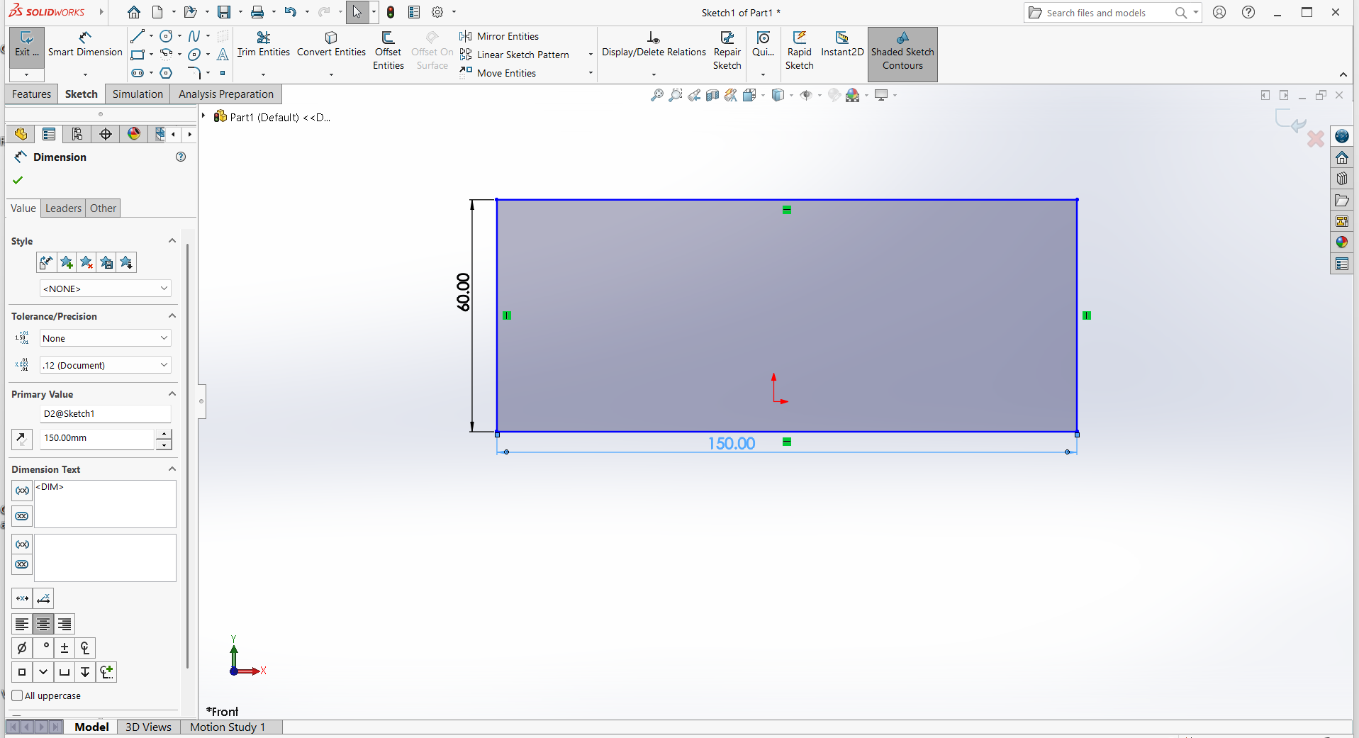
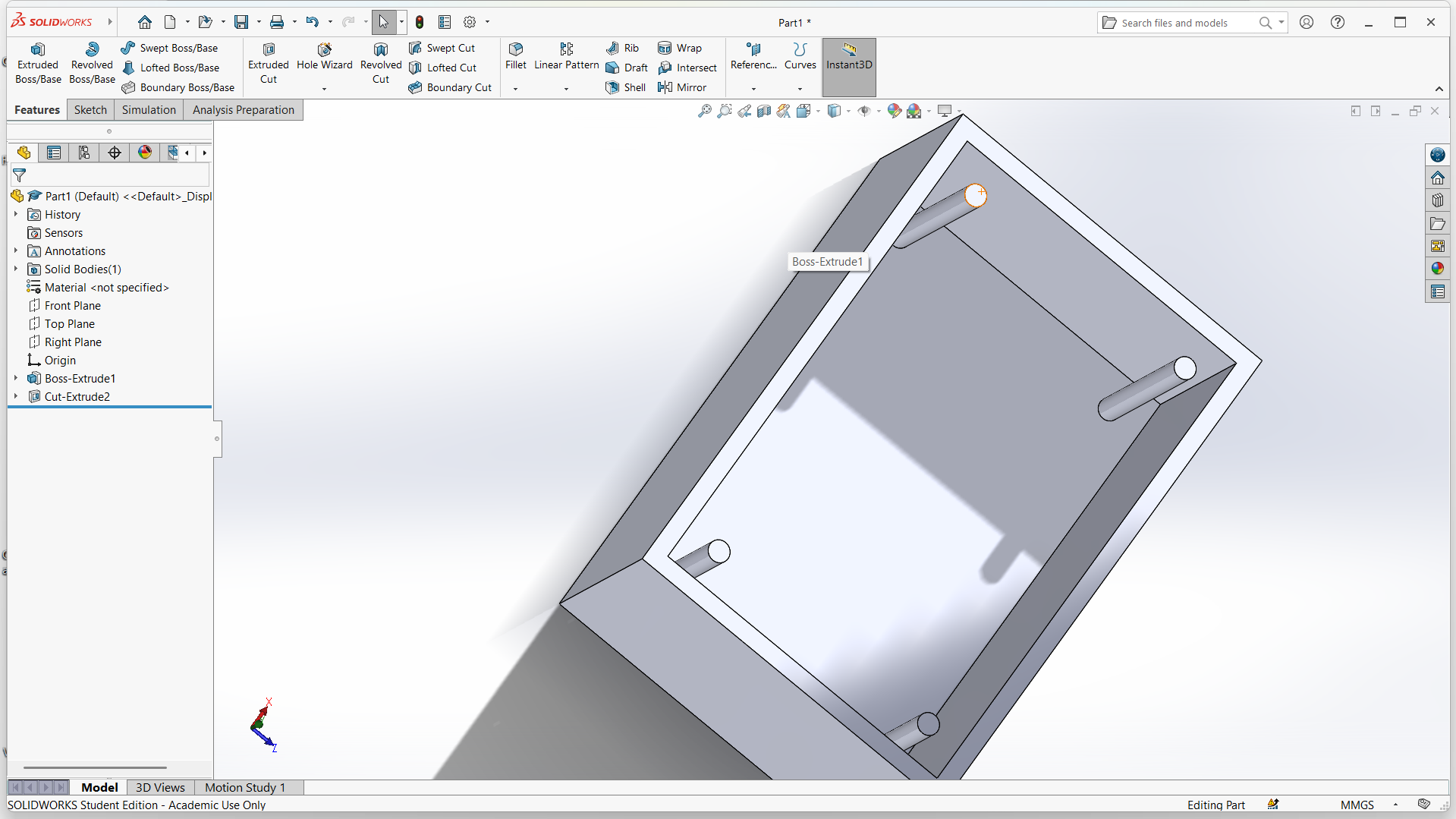
I used extrude-bose to make 3D object of the box. Created circles using eclips tool, then applied extrude-cut to make screw area and the inner part of the box
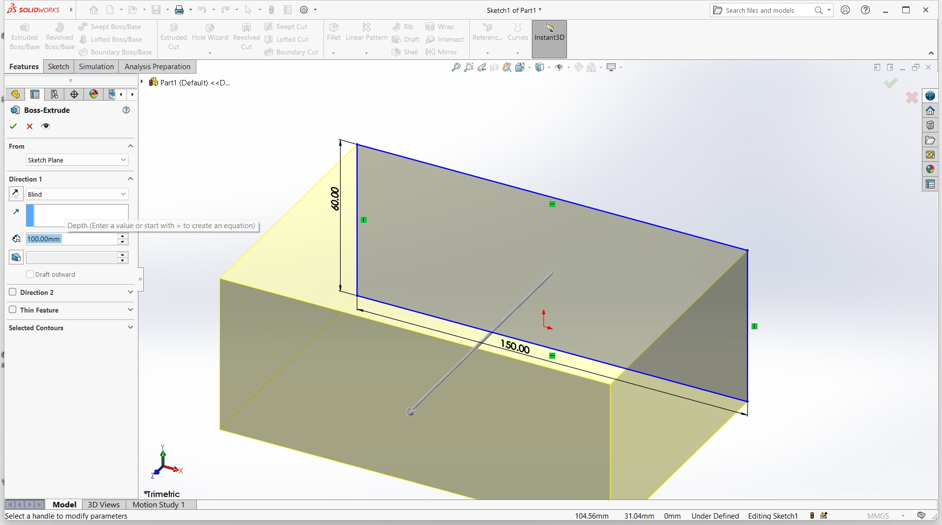
The container after extrude
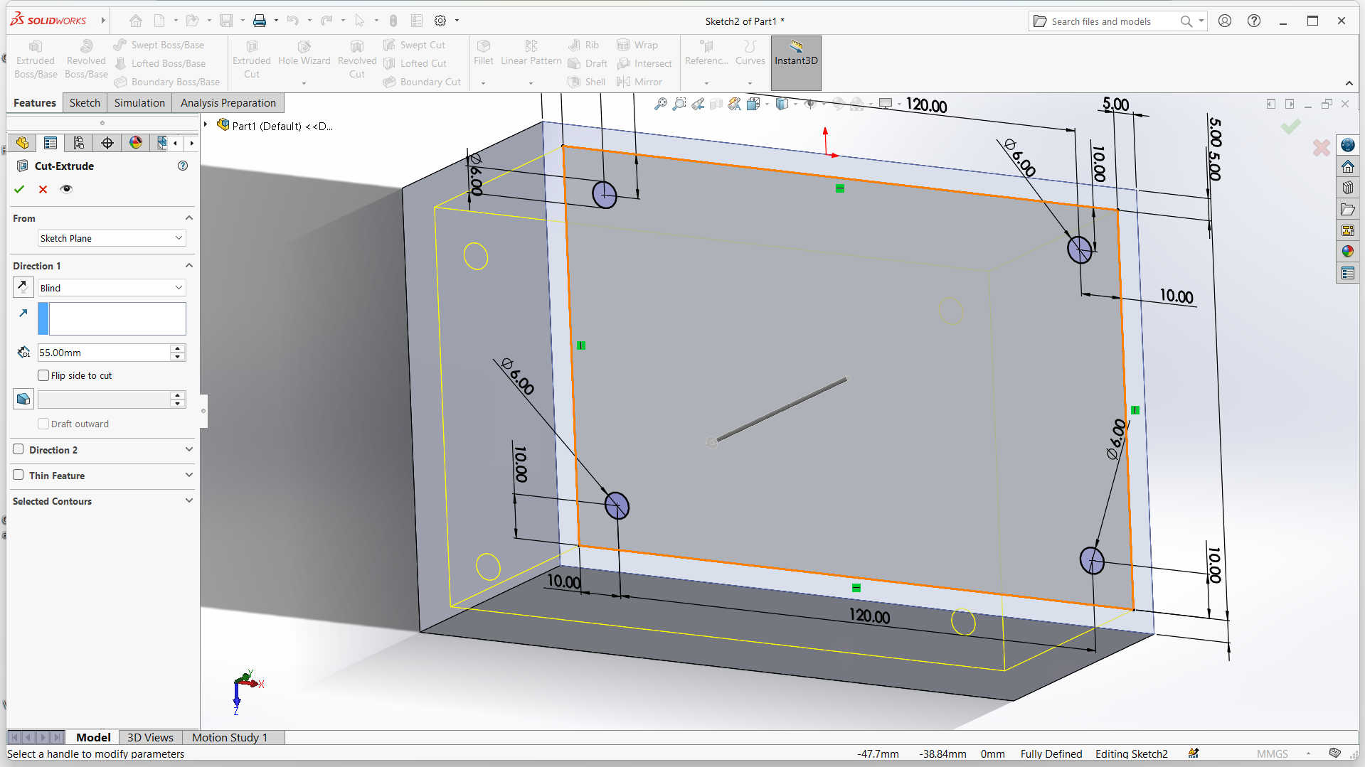
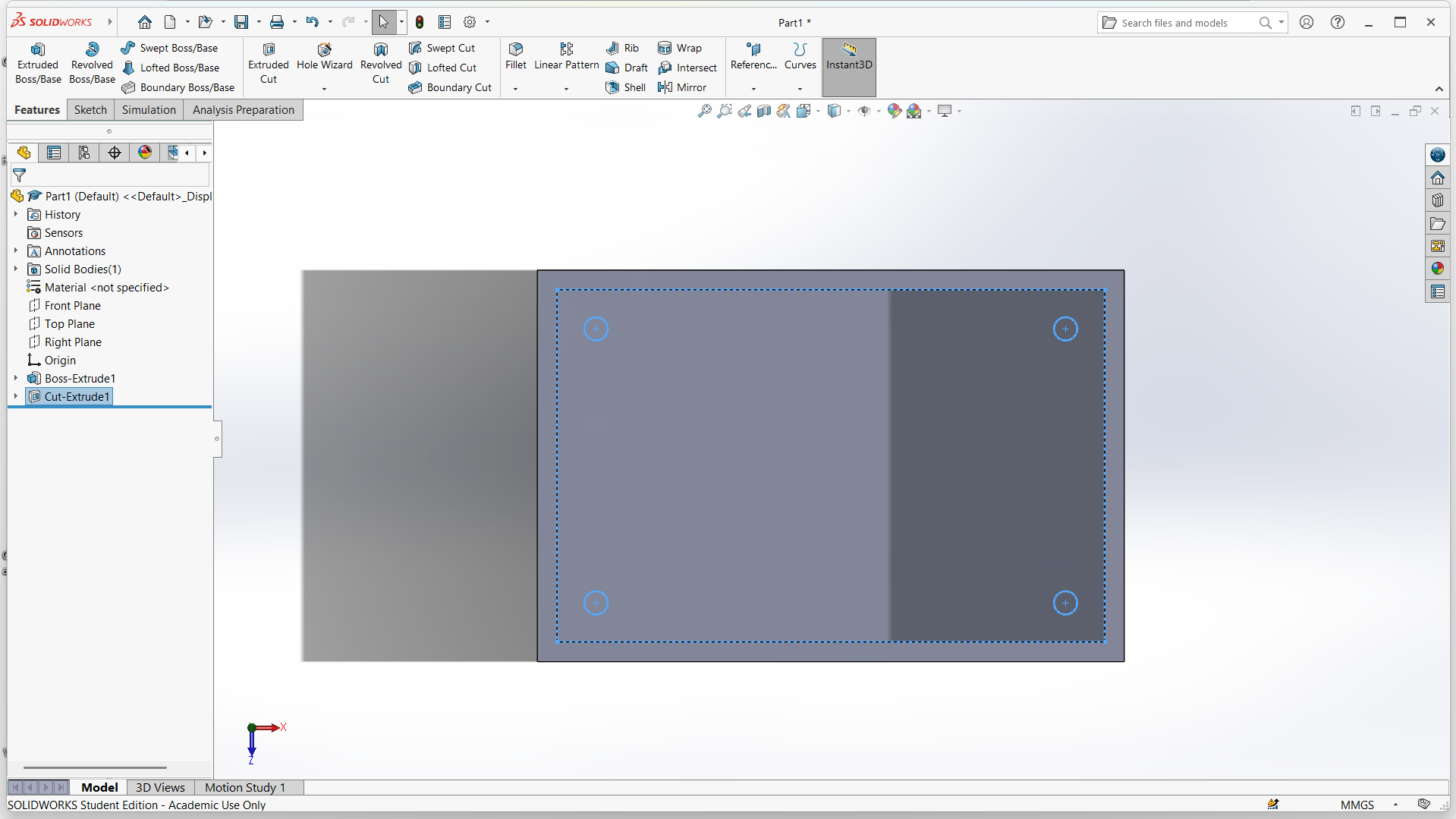
Created sketch 2 to make box top, selected top part of the box and the holes, then extrude boss.
I then extrude-cut
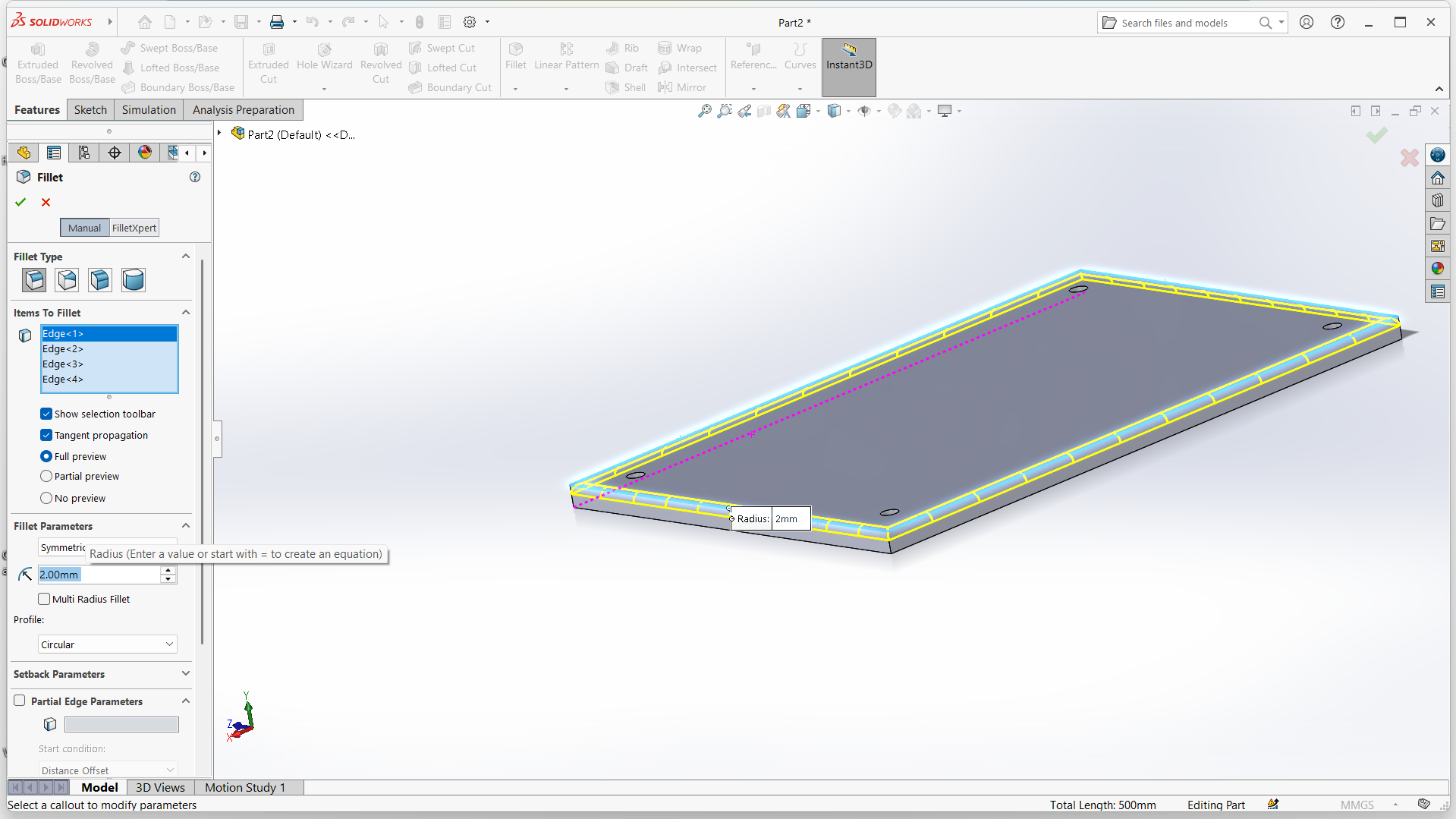
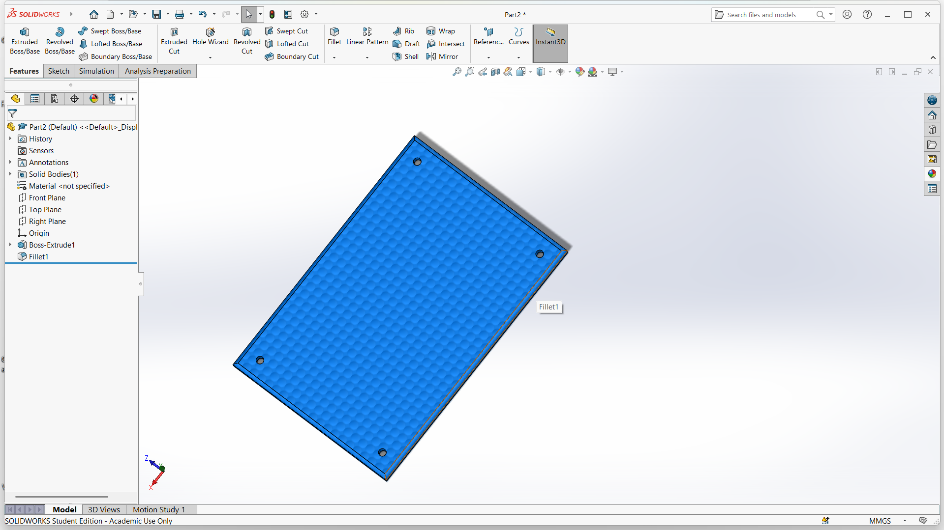
I used fillet to make smooth edges of the box-top.
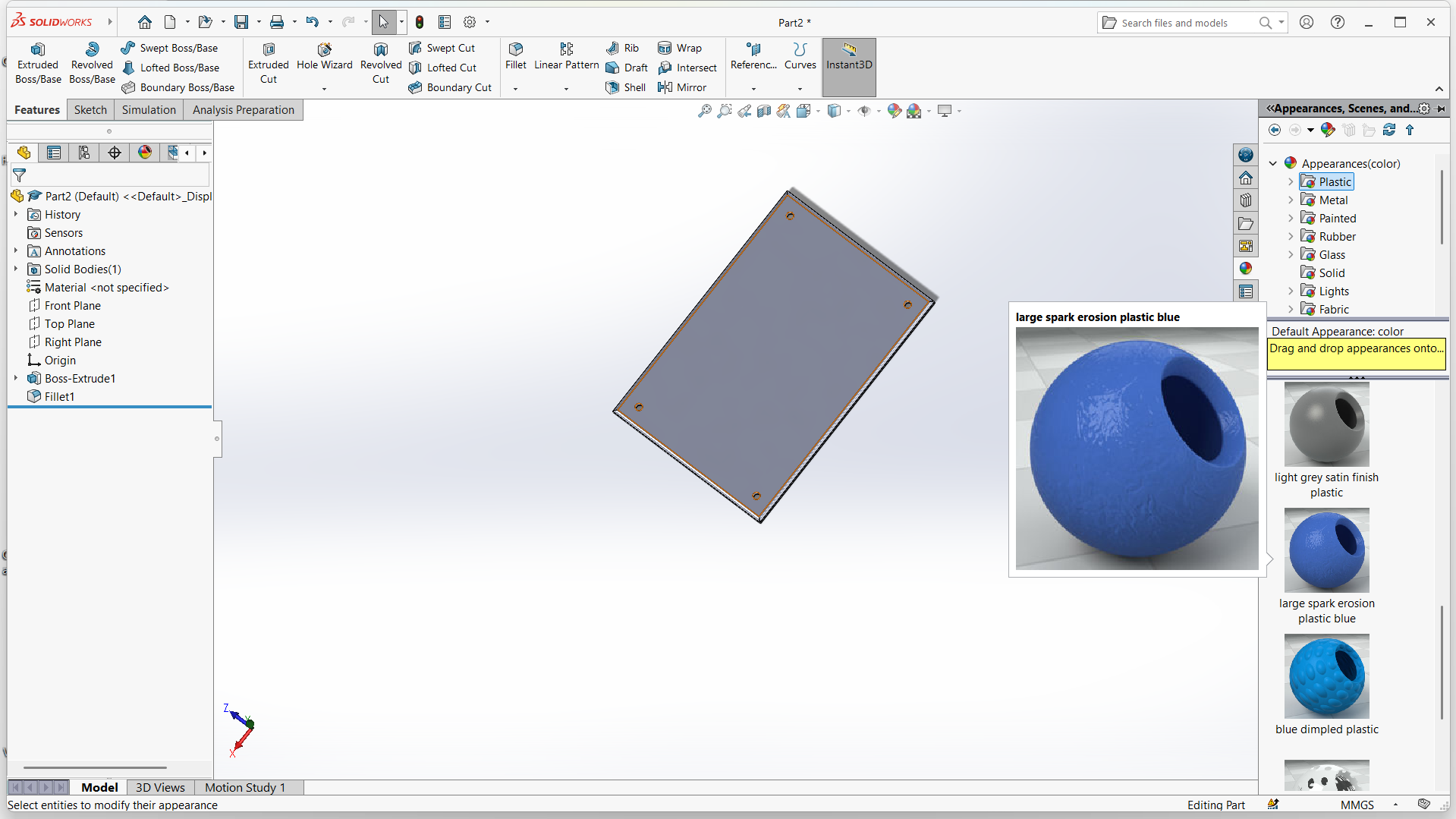
Changed the top appearance under appearance color. Then applied large spark erosion plastic.
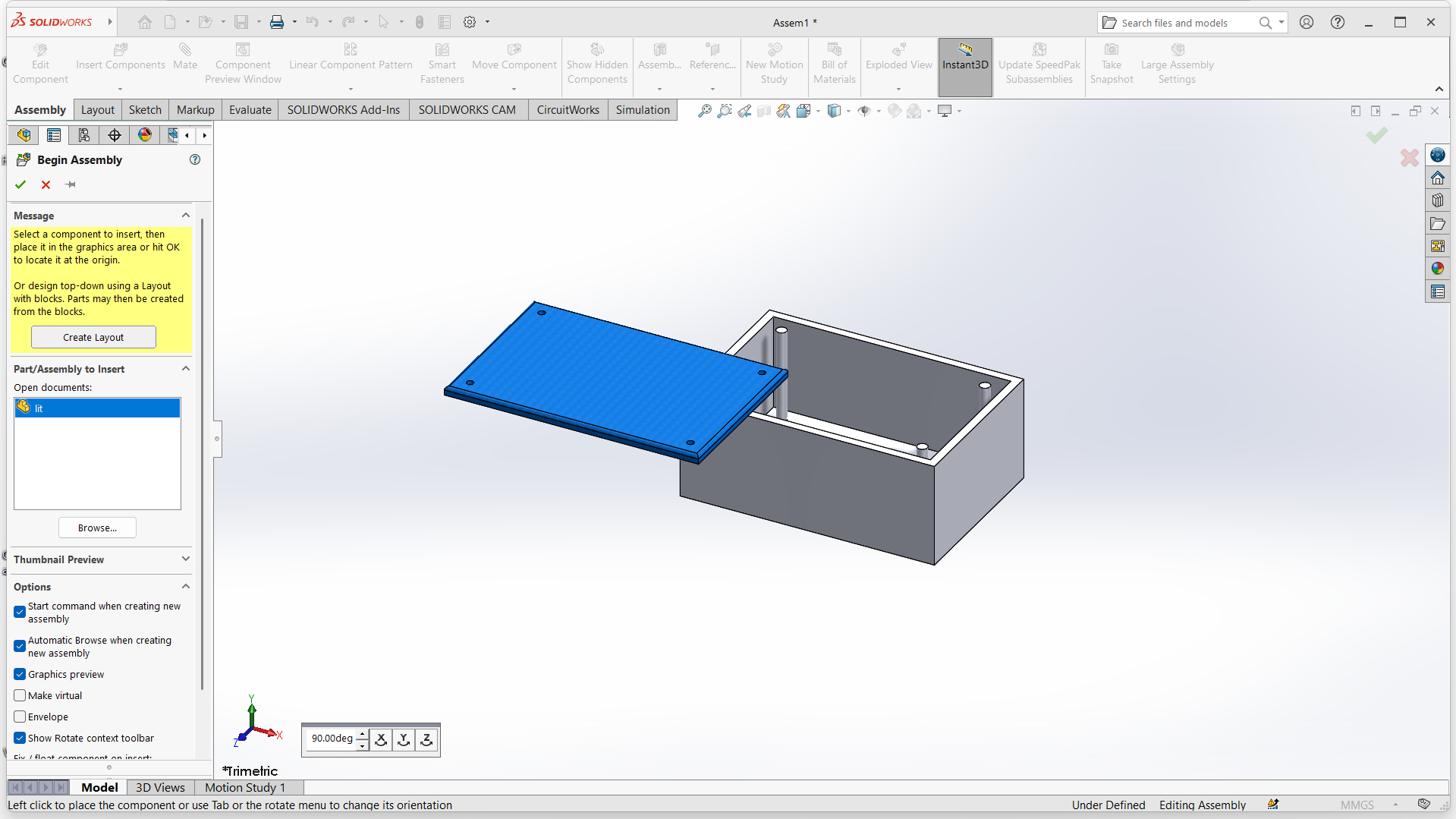
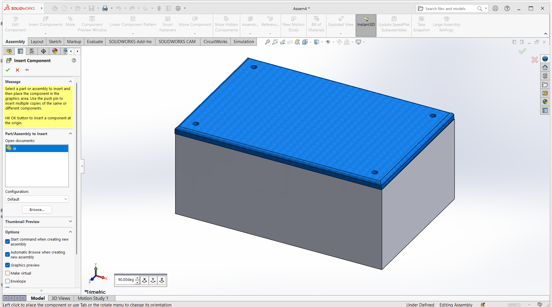
I selected assemble and selected projects to assemble.
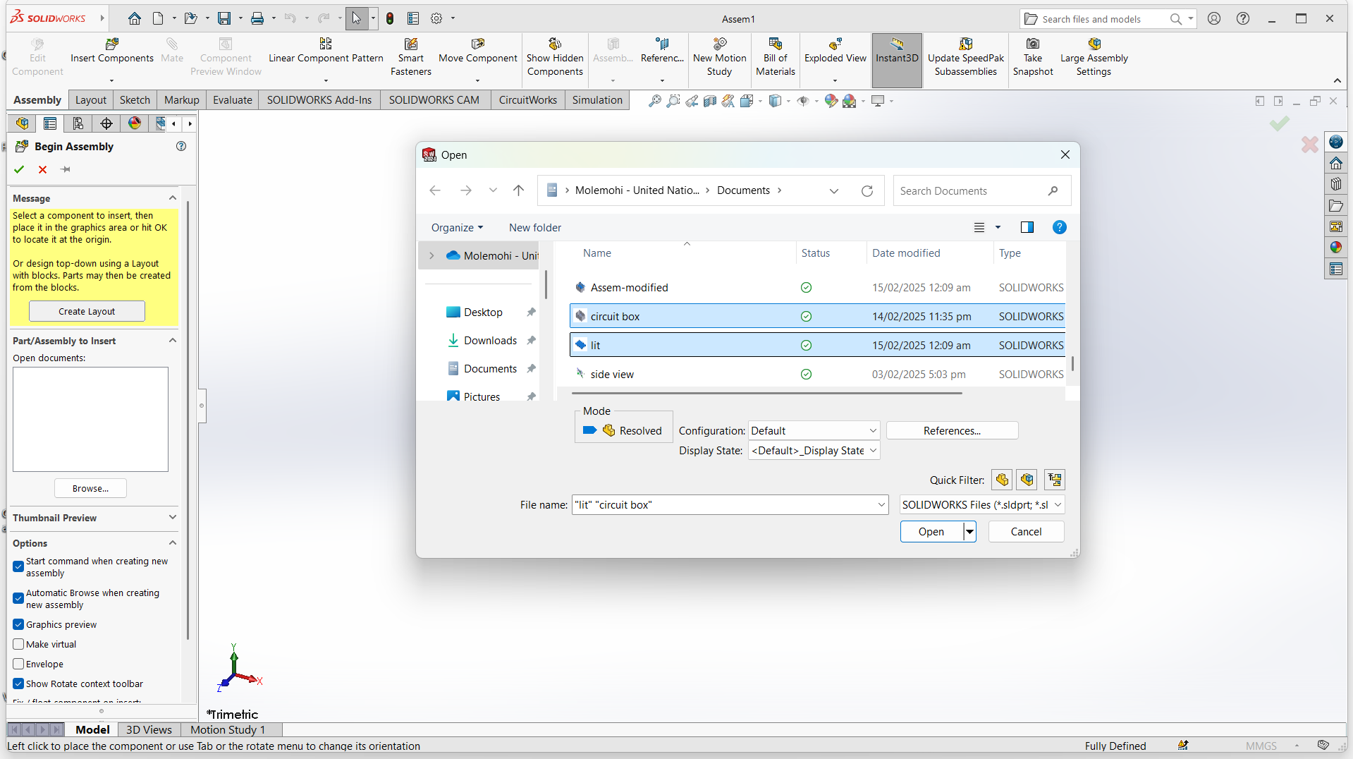
Drag objects to assemble. The product after assemble.
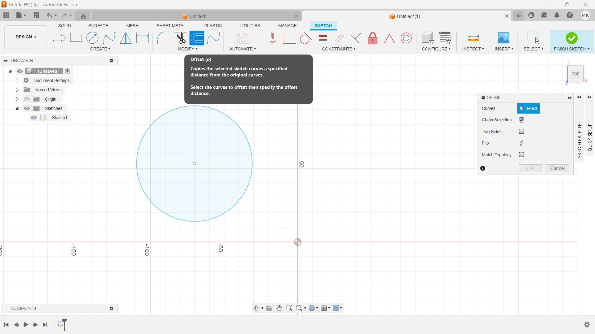
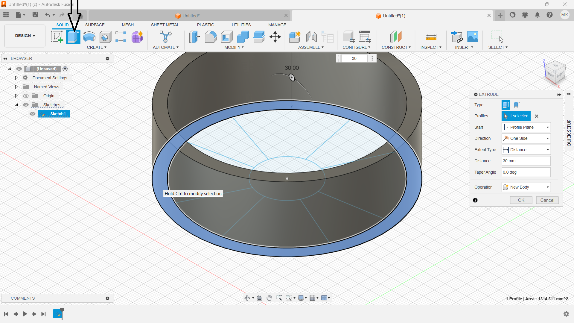
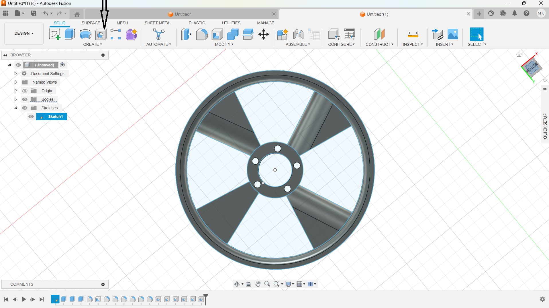
Firstly I opened the fusion application and created sketch. Then selected a plane to do designs
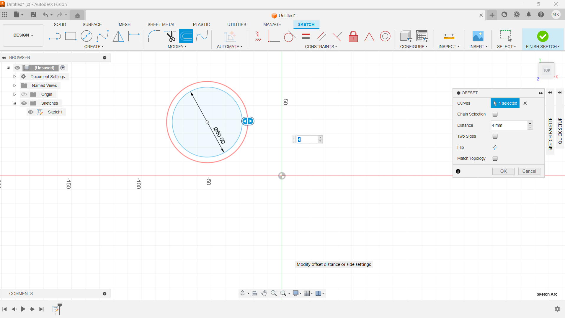
I created a circle using circle tool, and made the size of the rim layer using offset tool.
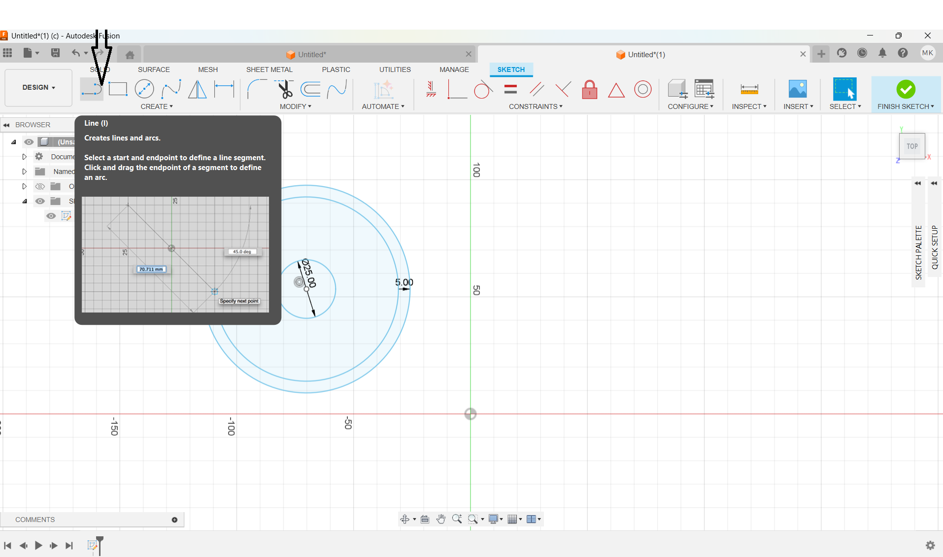
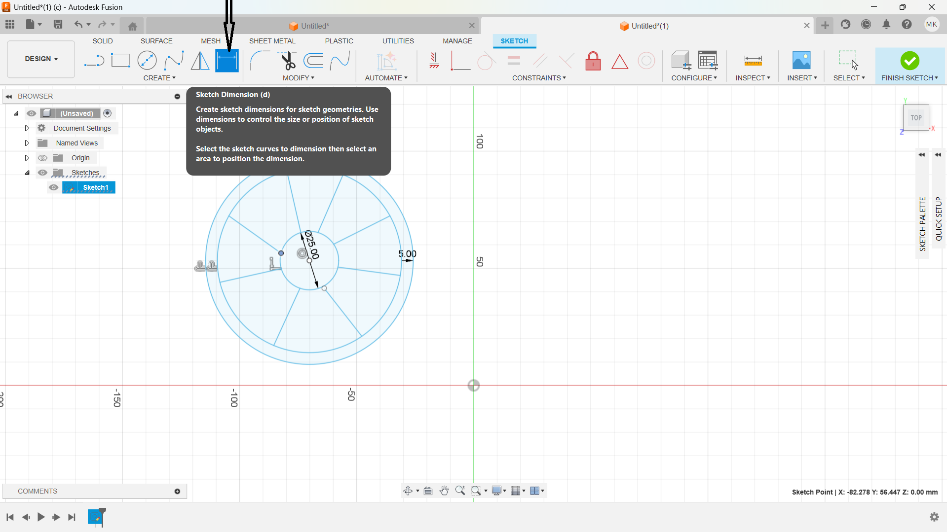
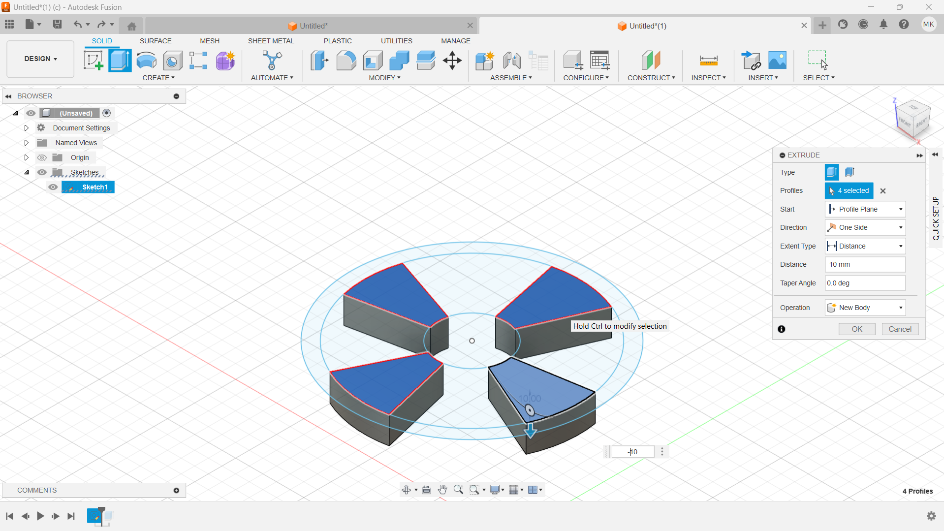
I used line tool to create inner parts of the rim, and used sketch dimension to give the rim precise dimansions.
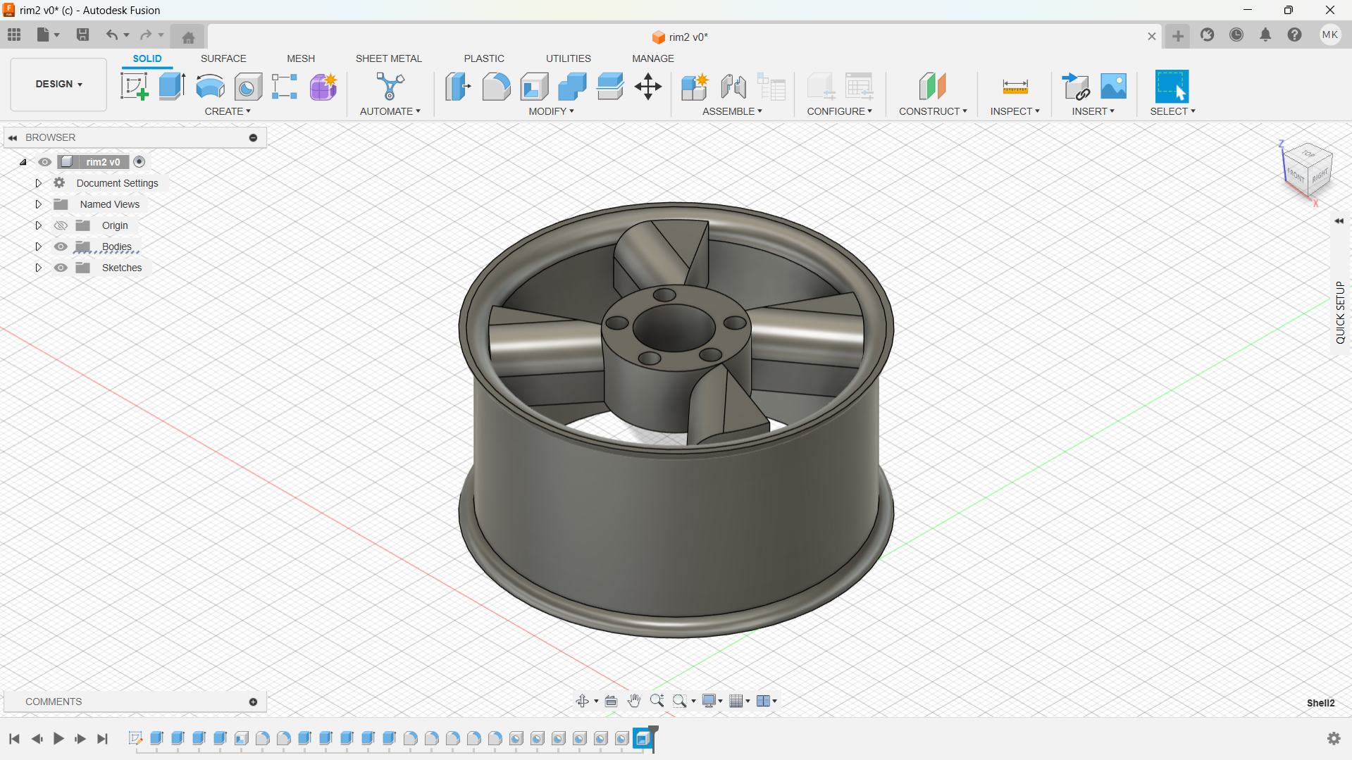
I used extrude tool to creat width of the rim, inner parts.
Created smooth inner edge and inner parts of the rim using fillet tool.
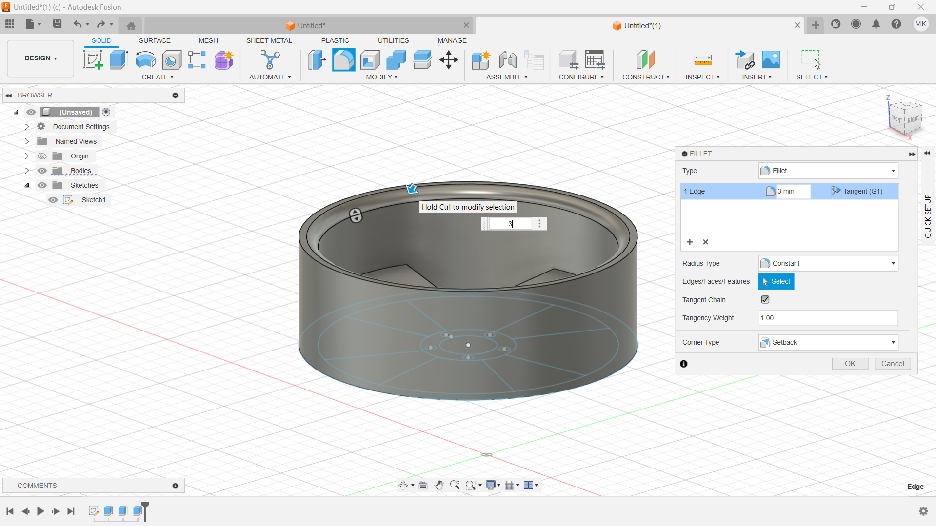
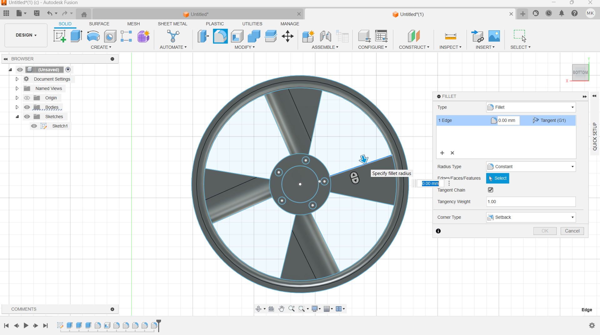
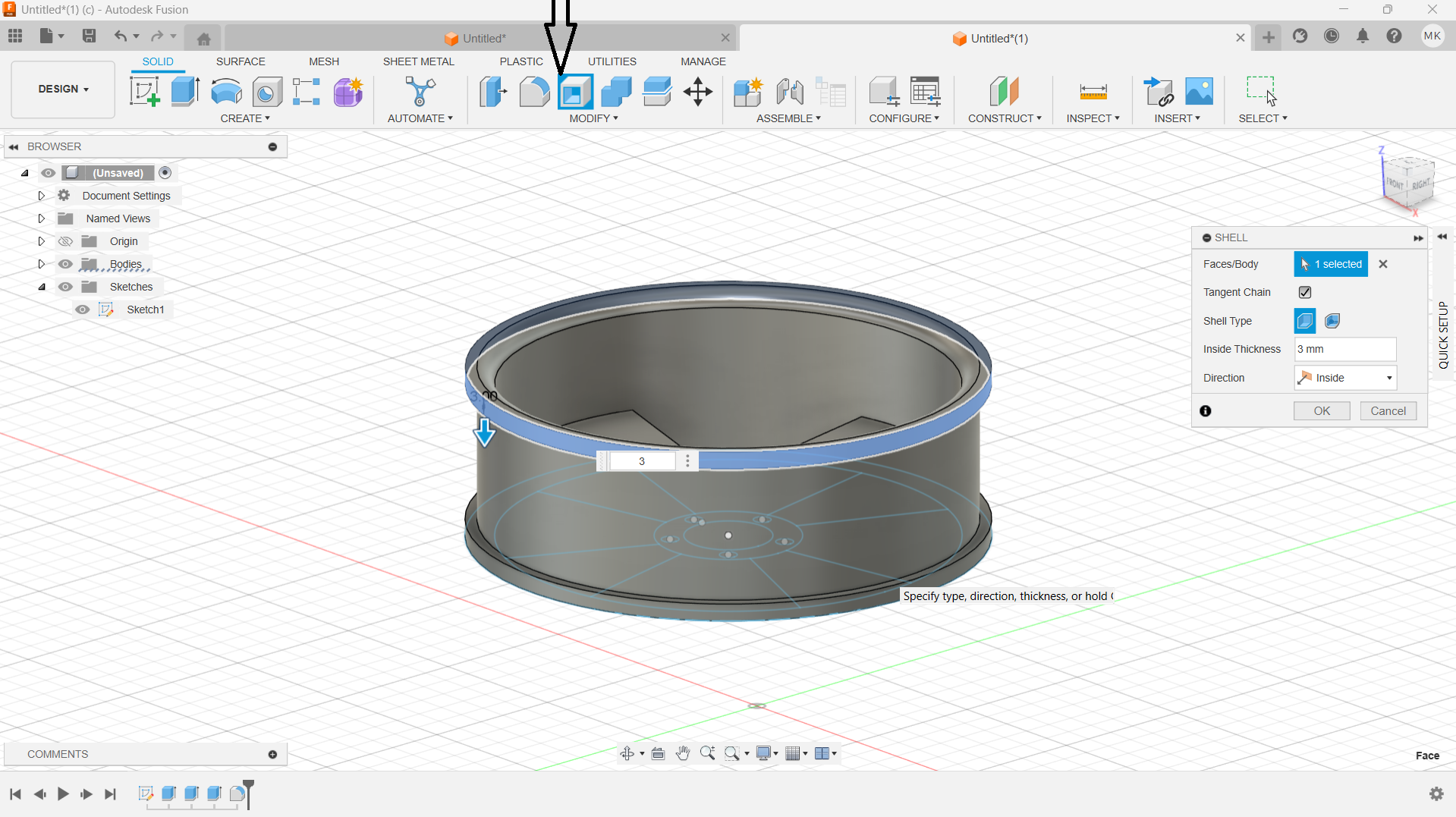
Used hole tool to create rim holes. Also used shell tool to make tyre space on the rim.
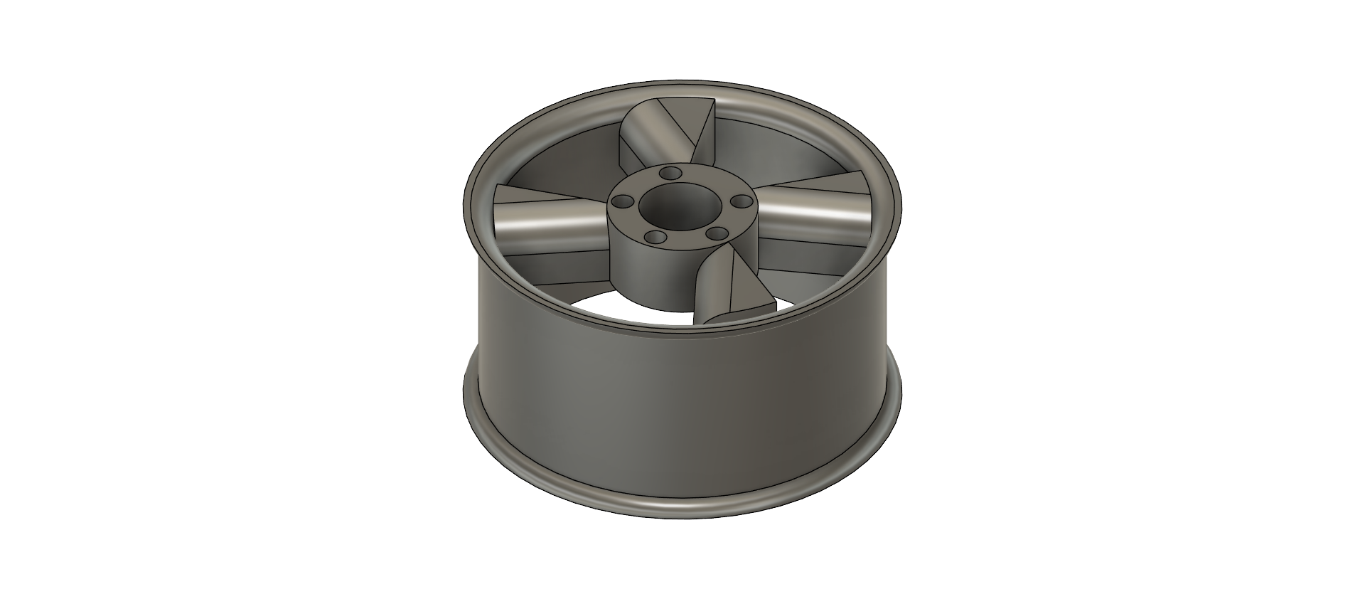
Final product
I installed it using default settings, and selected for all user.
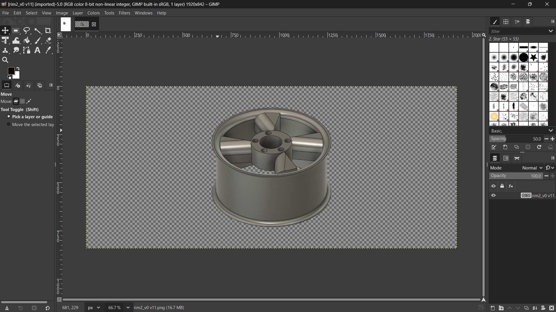
I used the rim made from with From the 3D design using Fusion. The image of the rim exported from Fusion project by following these steps:
-Go to File menu: In Fusion 360, navigate to "File".
-Select Capture Image: Choose "Capture Image" from the menu.
-Set Resolution: You can customize the image resolution if needed.
-Save as png: In the save dialog, choose a file name, ensure the file type is png.
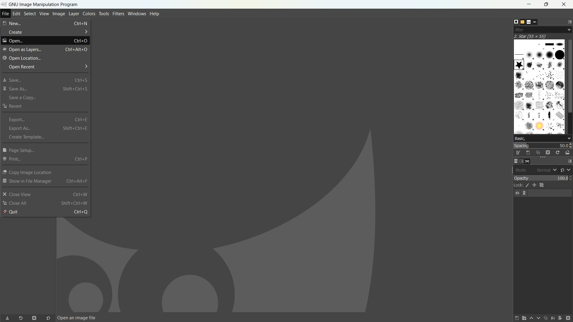
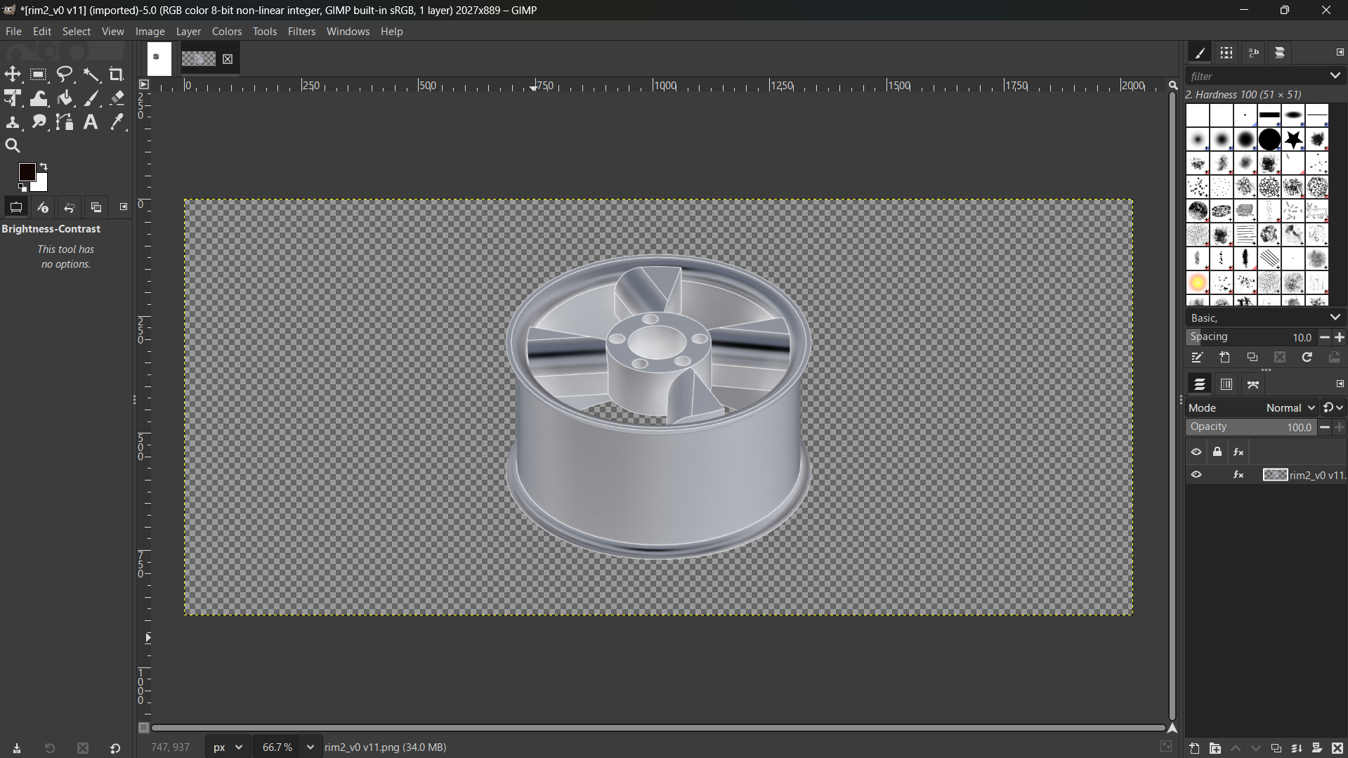
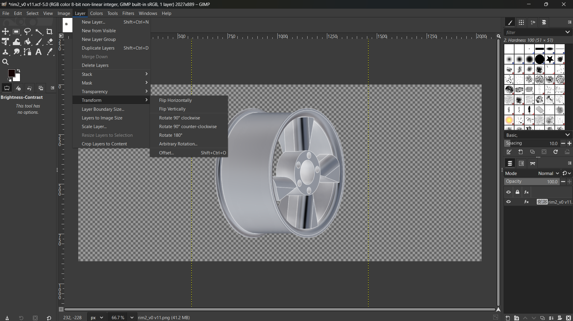
Firstly I opened the Gimp application and navigated to file to open the image to edit.
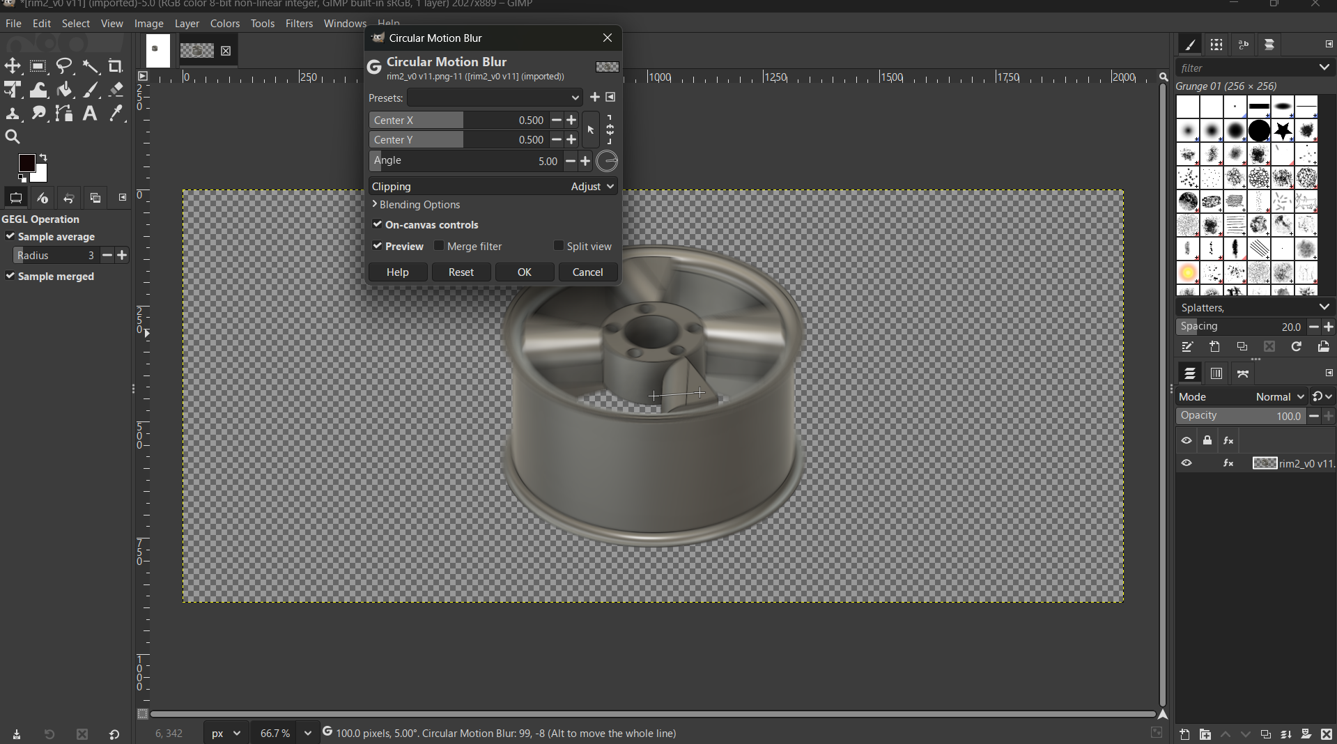
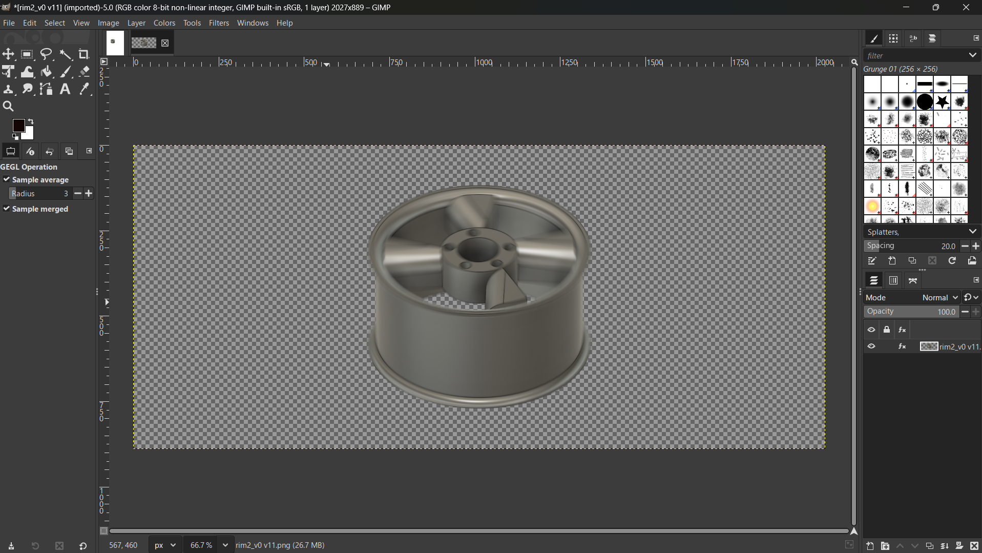
I used diffent filters to explore how the image will look like after applying those filters.
Went to Filters>Blur, and used Circular Blur and Zoom Motin Blur.
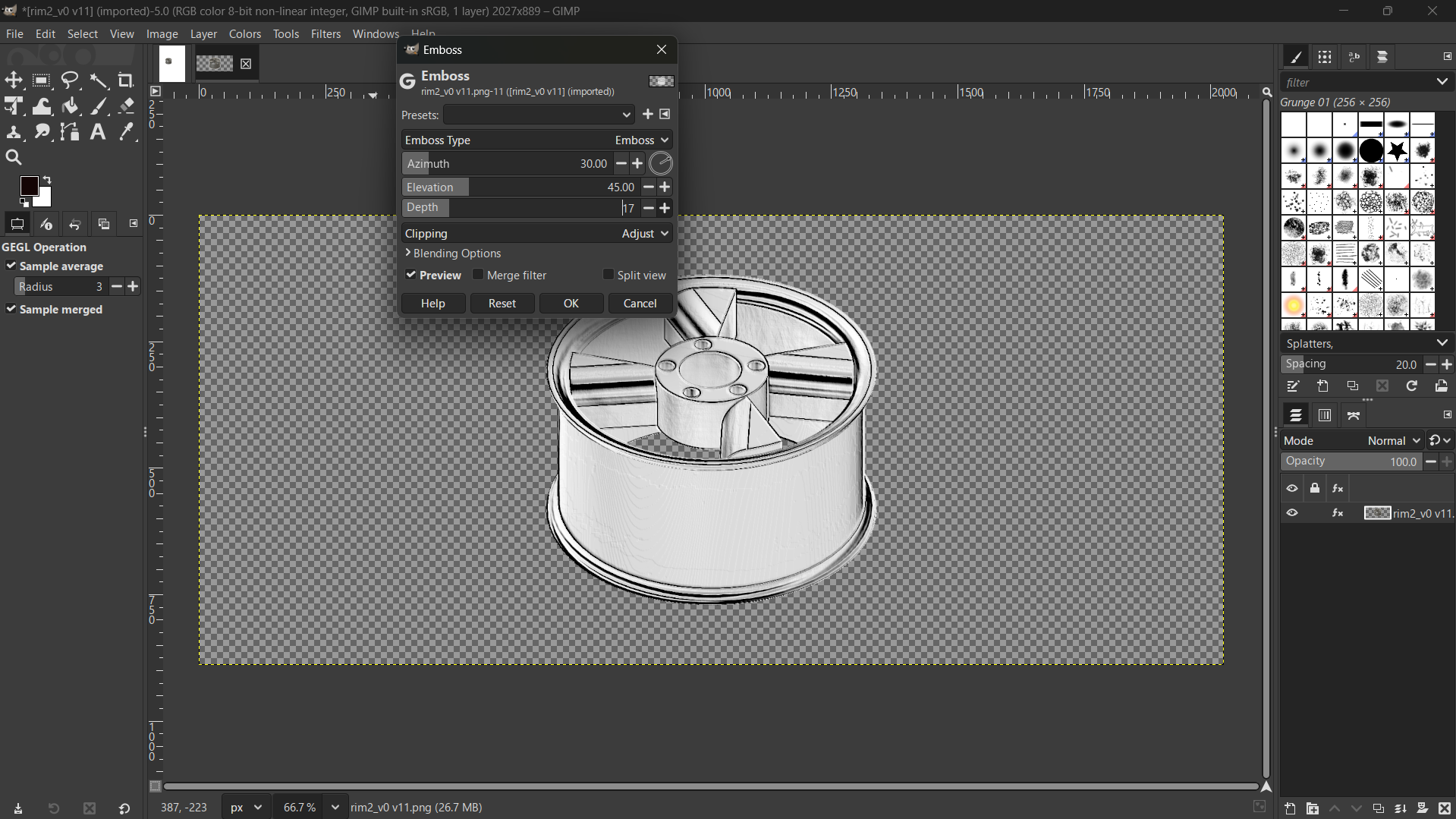
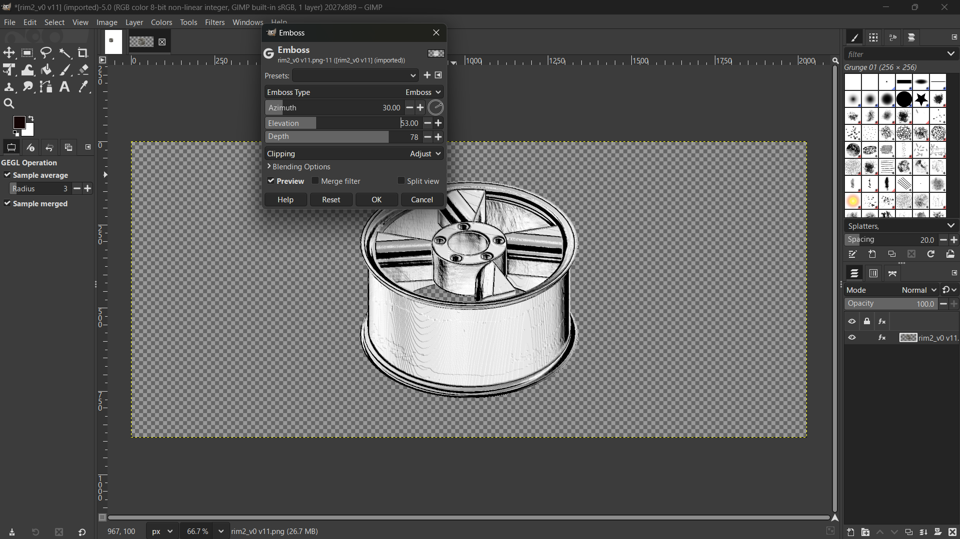
Filters>Blur>Emboss.
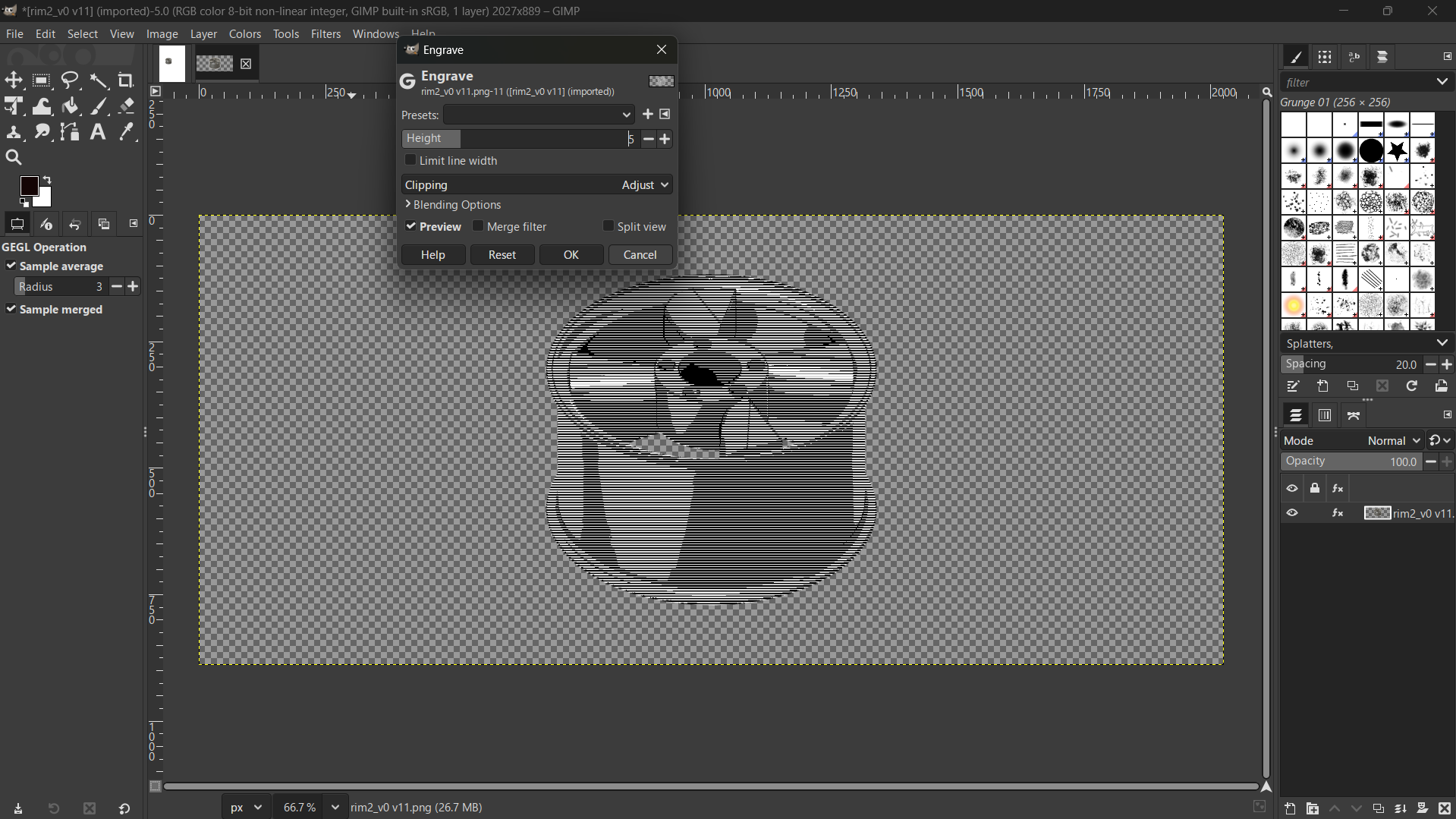
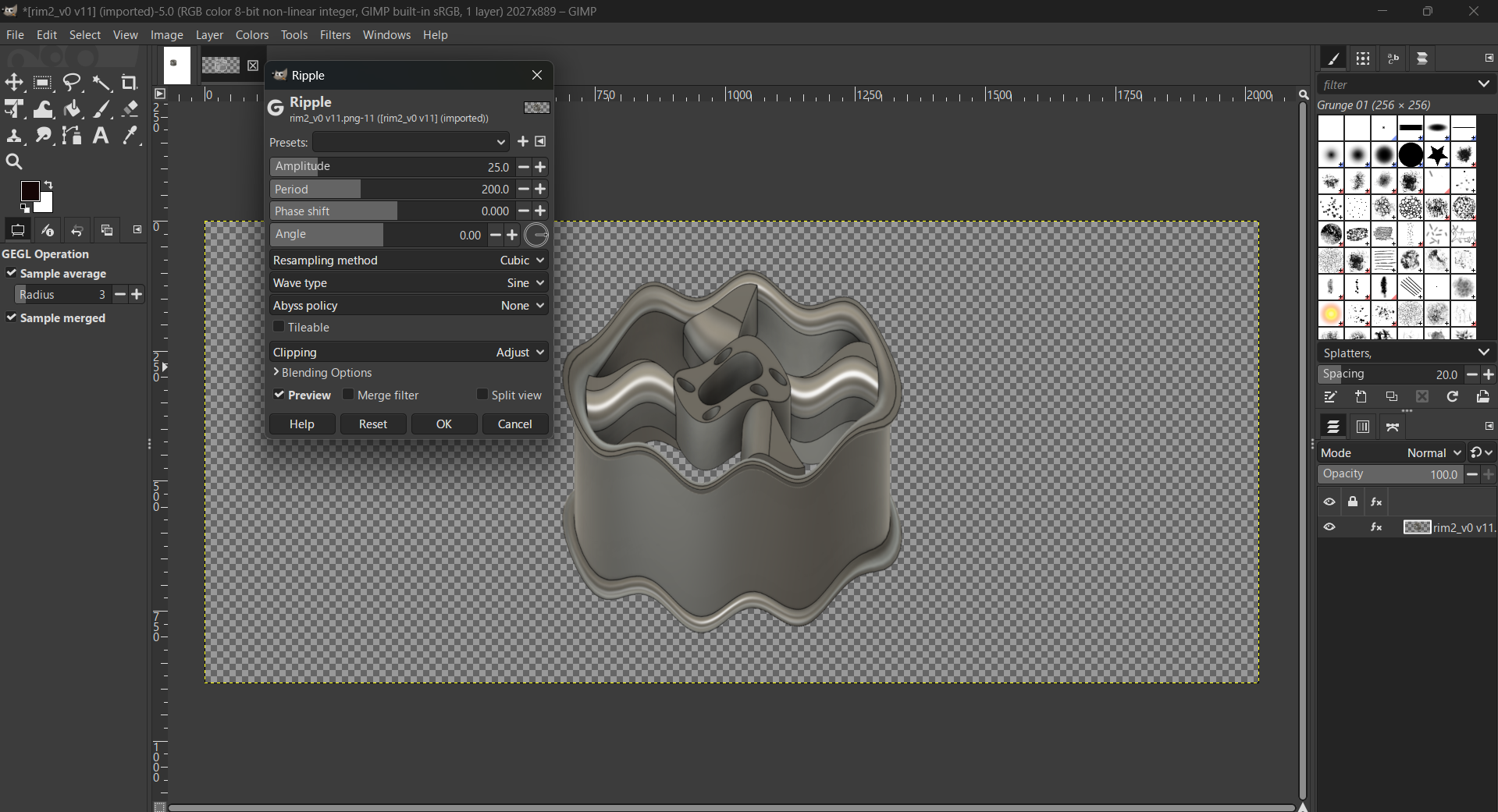
Filters>Blur>Encrave, and Ripple
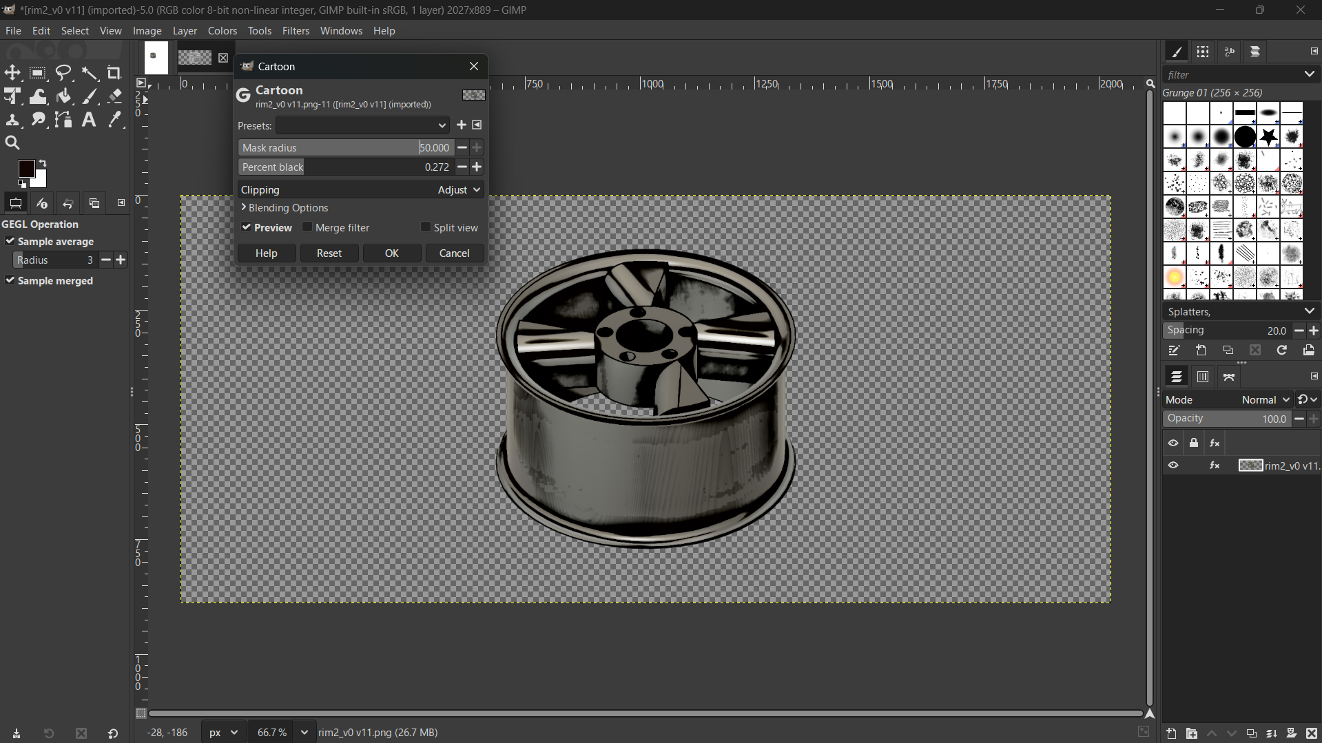
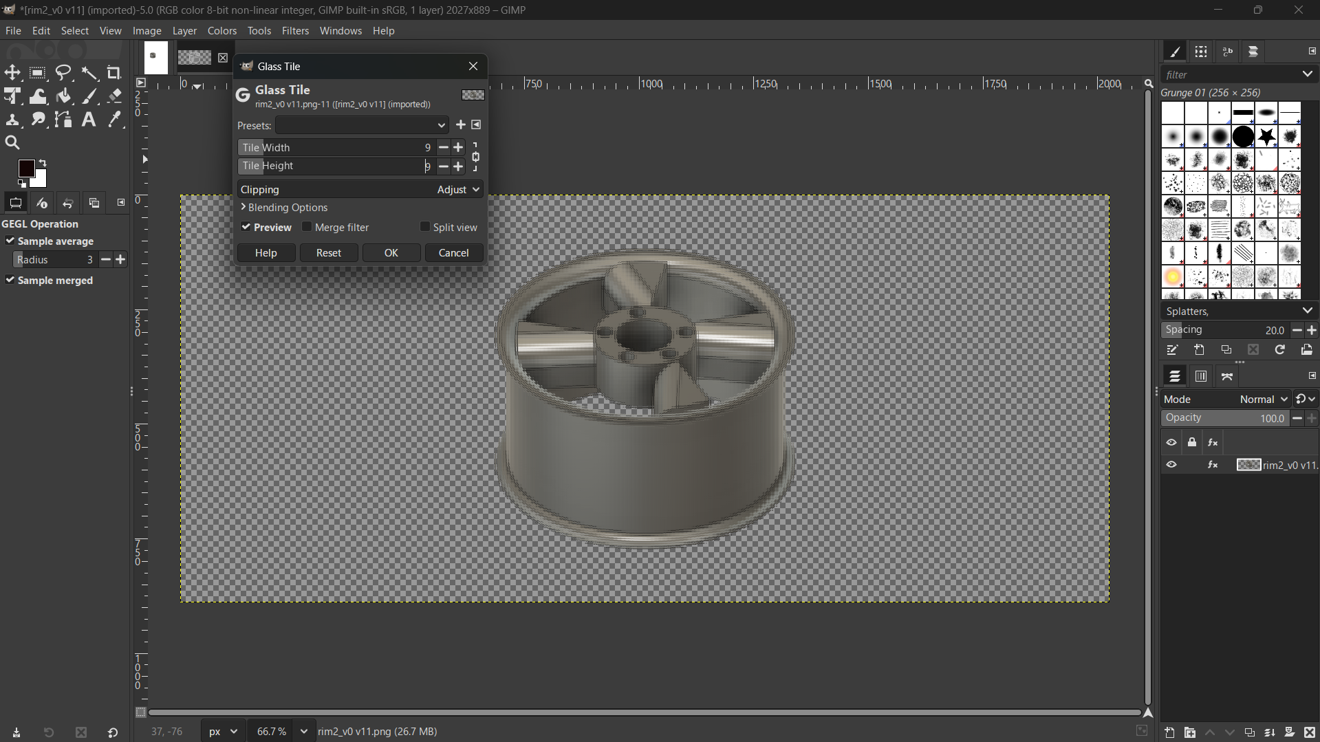
Filters>Artistic> Catoon, and Glass Tile.
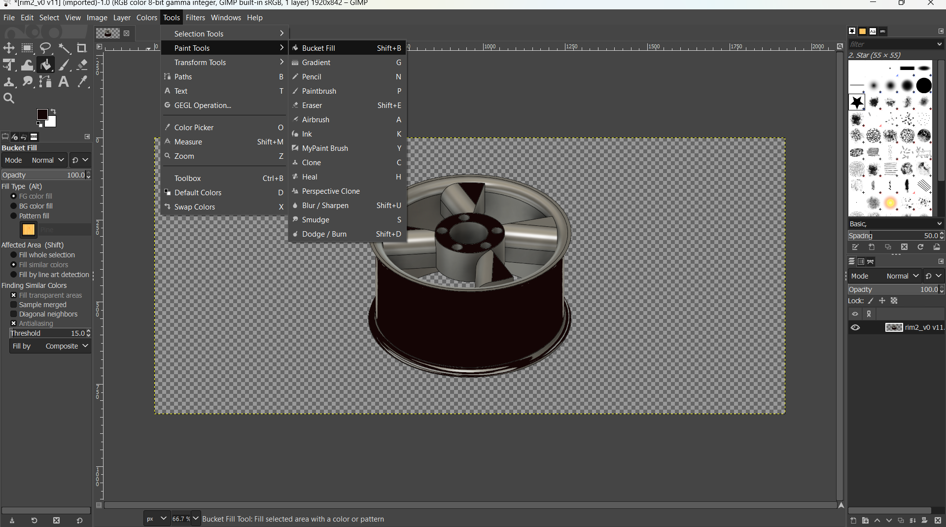
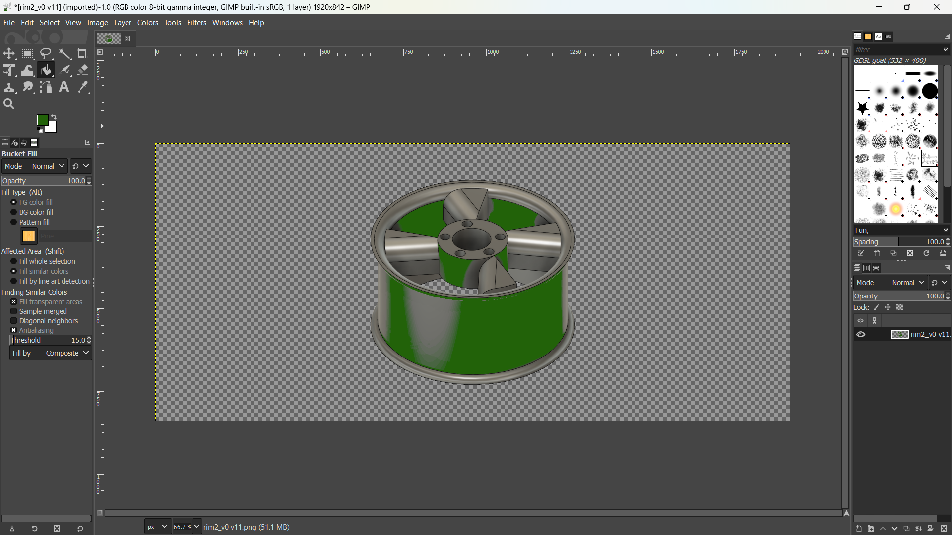
Tools>Paint>Backet Fill
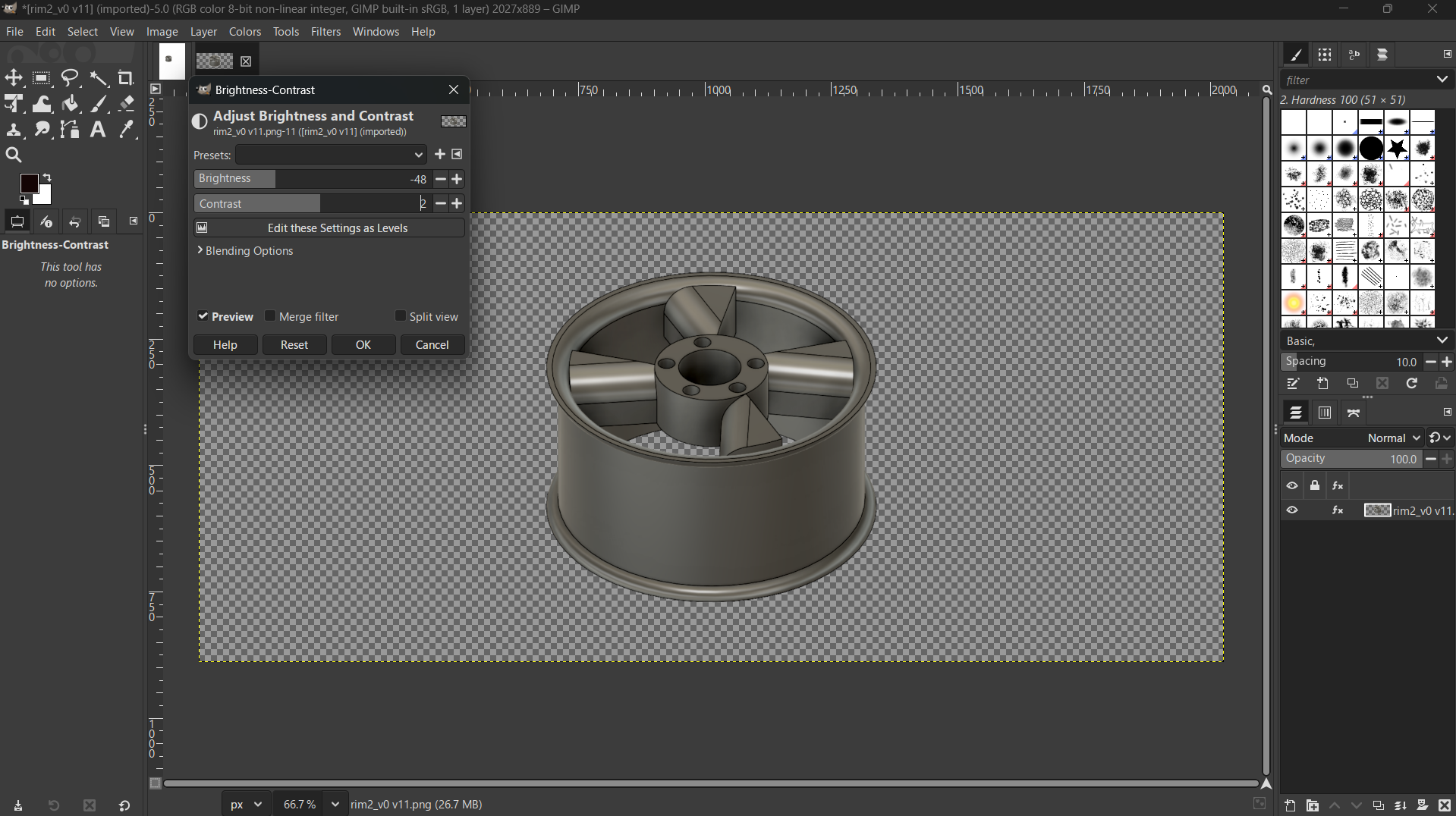
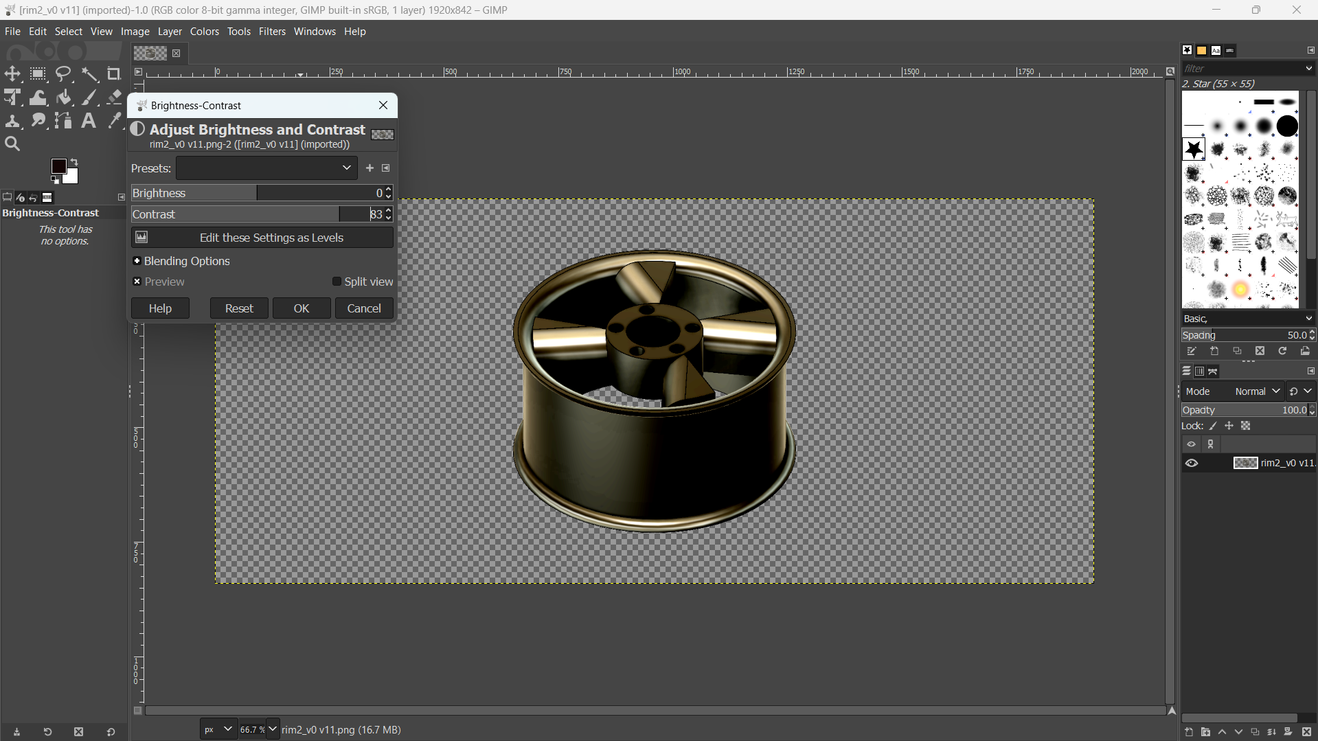
Color>Brightness Contrast.
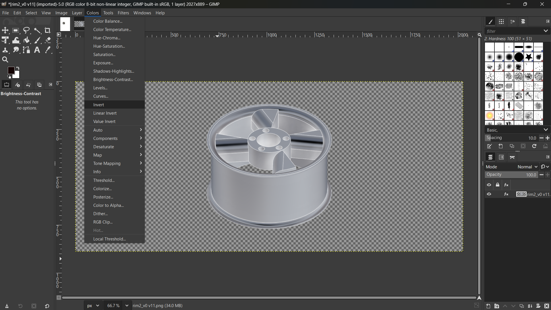
Color>Invent.
Layer>Transform>Rotate 90 Clockwise.
Design Files
Tray-CorelDraw Vector
Rim-Fusion 3D
Box-Solidworks 3D
Rim-Gimp Raster