Embedded Networking and communication
Description of group assignment
-
Document your work to the group work page and reflect on your individual page what you learned
-
design, build and connect wired or wireless node(s) with network or bus addresses and a local input and/or output devices
Goup assignment
Individual assignments
Group assignment
For this week’s Embedded Networking and Communication Group Assignment, we collaborated to send messages between different microcontroller boards. I worked with my peers to set up UART communication between two projects — one using my Xiao board and other were using also Xiao boards
Through this hands-on collaboration, I better understood how embedded systems communicate and the importance of timing, pin mapping, and protocol configuration. You can find the full group documentation on our shared group assignment page.
Individual assignment
This week, I explored the fascinating world of embedded networking and communication. The main goal was to make two microcontrollers communicate with each other. I used my custom board based on the Seeed Xiao microcontroller and paired it with an Arduino Uno. I used Arduino IDE for coding, uploading, and serial monitoring.
Tools and Components
- Seeed Studio Xiao Board
- Arduino Uno
- USB Cables and Jumper Wires
- Arduino IDE
Setting Up the Hardware
I started by connecting my Xiao board that I have built in week8-electronic-production and Arduino Uno using serial communication (UART) through their TX and RX pins. I made sure both boards shared a common ground.
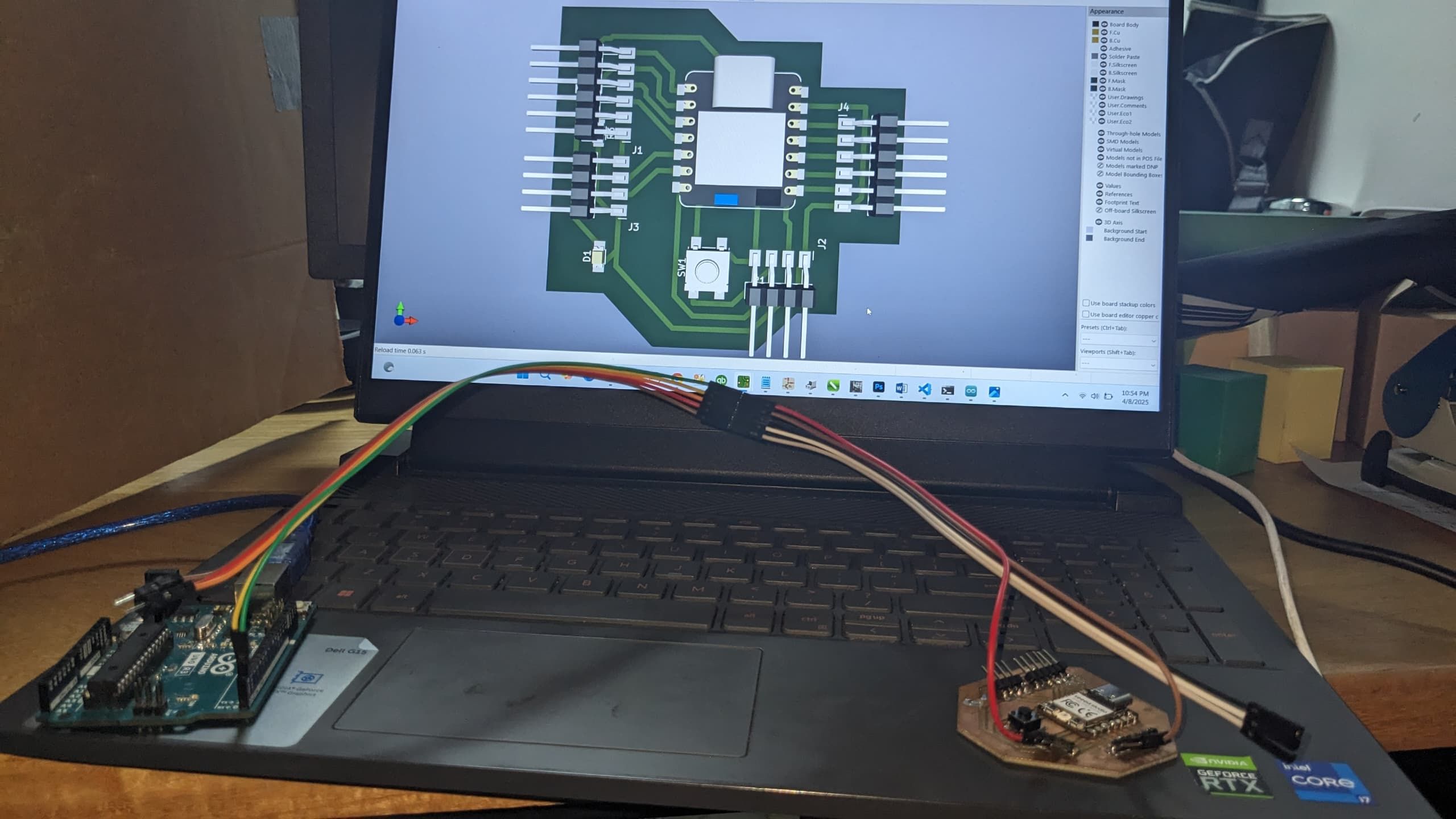
Image: Wiring between Xiao and Arduino Uno
Wiring Details:
- Xiao TX → Uno RX
- Xiao RX ← Uno TX
- GND ↔ GND
Programming the Boards
I used Arduino IDE to program both boards. My Xiao board was programmed to continuously send data, and the Arduino Uno was set to receive and display that data via the serial monitor.
Xiao Code (Transmitter)
    void setup() {

        Serial1.begin(9600); //help in tx and rx

        Serial.begin(9600); //communication pcb via usb

        }


        void loop() {

        if(Serial1.available()) {

          char c = Serial1.read();

          Serial.print("received from board2");

          Serial.println(c);

        }

        }
Arduino Uno Code (Receiver)
    void setup() {

        Serial.begin(9600);

        Serial.println("hello other board");

        }


        void loop() {


        }
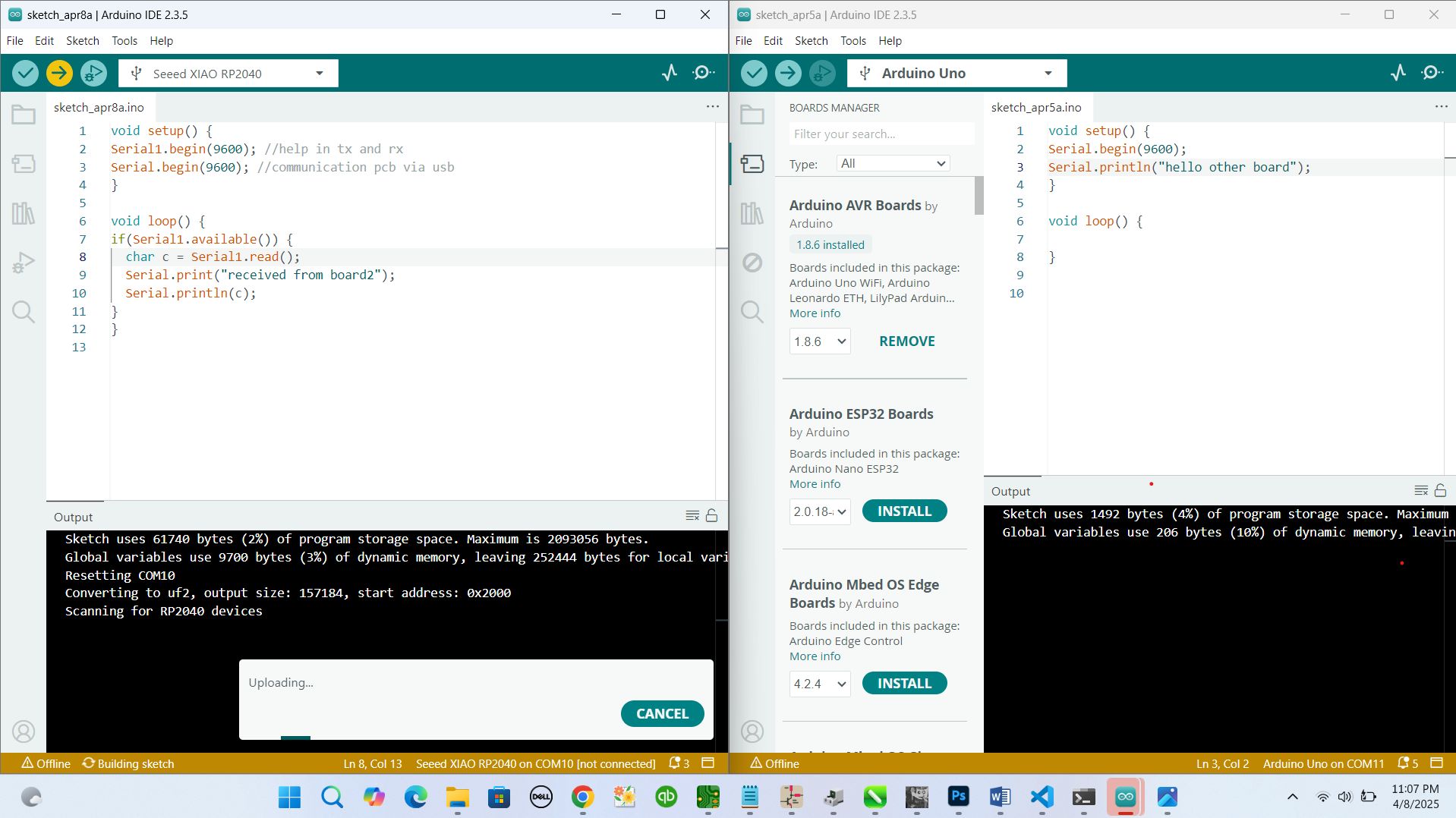
Image: Serial Monitor showing received data
Testing the Communication
Once both codes were uploaded, I opened the Serial Monitor for the Arduino Uno. The messages from the Xiao board began showing up every second, just like expected. It was a simple “Hello from Xiao!”, but seeing it arrive correctly was a satisfying moment.
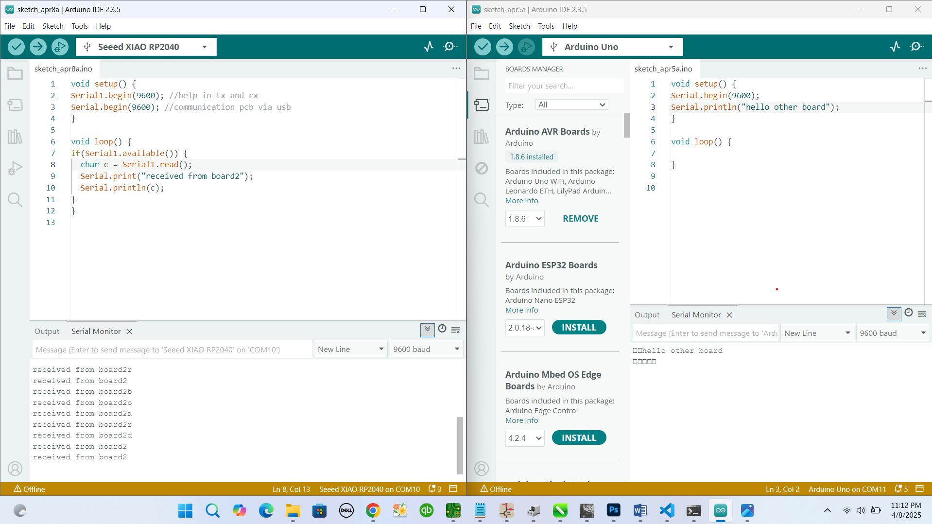
Image: Diagram showing how data flows between the boards
adding output device
after making connection that will help me to do communication between two boards, I added output device to see how it can work
components added are:
- joystick board
- servo motor
- power supply
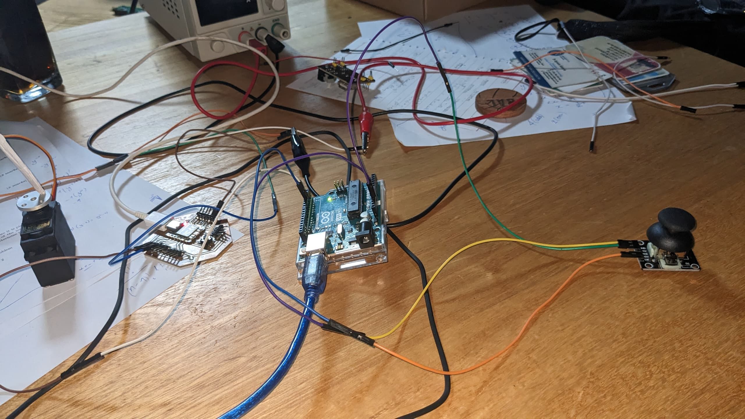
after selecting components to use I connected them and I genereted new codes that include all components that I used
here is the image showing the codes
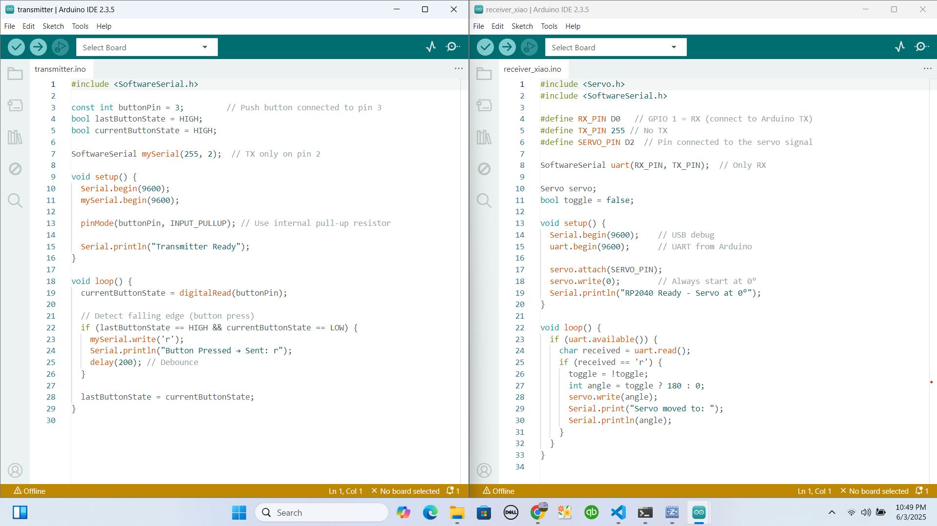
then I uploaded the codes to board and I set Xiao to be receiver and arduino to be Transmitter
Xiao Code (Transmitter)
    #include <Servo.h>
#include <SoftwareSerial.h>

#define RX_PIN D0
#define TX_PIN 255
#define SERVO_PIN D2

SoftwareSerial uart(RX_PIN, TX_PIN);

Servo servo;
bool toggle = false;

void setup() {
  Serial.begin(9600);
  uart.begin(9600);

  servo.attach(SERVO_PIN);
  servo.write(0);
  Serial.println("RP2040 Ready - Servo at 0°");
}

void loop() {
  if (uart.available()) {
    char received = uart.read();
    if (received == 'r') {
      toggle = !toggle;
      int angle = toggle ? 180 : 0;
      servo.write(angle);
      Serial.print("Servo moved to: ");
      Serial.println(angle);
    }
  }
}
Arduino Uno Code (Receiver)
    #include <SoftwareSerial.h>

const int buttonPin = 3;
bool lastButtonState = HIGH;
bool currentButtonState = HIGH;

SoftwareSerial mySerial(255, 2);

void setup() {
  Serial.begin(9600);
  mySerial.begin(9600);

  pinMode(buttonPin, INPUT_PULLUP);
  Serial.println("Transmitter Ready");
}

void loop() {
  currentButtonState = digitalRead(buttonPin);

  // Detect falling edge (button press)
  if (lastButtonState == HIGH && currentButtonState == LOW) {
    mySerial.write('r');
    Serial.println("Button Pressed → Sent: r");
    delay(200);
  }

  lastButtonState = currentButtonState;
}
After getting everything in right way I powered powered my system and here is the demo for result
What I Learned
- How to use UART communication between two microcontrollers
- The importance of baud rate matching and proper wiring
- How to monitor serial communication using Arduino IDE
- how to contol output device using different board which is communicating to controller of the device
This week gave me a strong foundation in microcontroller communication. It was exciting to see how two boards could talk to each other using simple serial messages and also controll out devices. I’m now looking forward to experimenting with more advanced protocols and wireless modules!
Download original files
You can download the full arduino codes used for this assignment here:
Download Project Files for transmitter(arduino)Download Project Files for receiver(xiao)