Electronics Production
This is the 8th week where we were covering the electronic production.
this week complete week 6 because I'm going to print what I designed in week 6 and also I'm going to use the designing part to generate g-codes for printing
Description of group assignment
-
Characterize the design rules for your in-house PCB production process: document feeds, speeds, plunge rate, depth of cut (traces and outline) and tooling.
-
Document the workflow for sending a PCB to a boardhouse
-
Document your work to the group work page and reflect on your individual page what you learned
-
Make and test a microcontroller development board that you designed
Goup assignment
Individual assignments
Group assignment
In this week’s Electronics Production Group Assignment, I explored the design rules for our in-house PCB production process, including feeds, speeds, plunge rate, depth of cut for traces and outlines, and tooling specifications. Through our group assignment link, we documented the workflow for fabricating PCBs, from material preparation to milling and soldering. This process enhanced my understanding of PCB manufacturing constraints and best practices, helping me improve my precision in board design and production.
Individual assignment
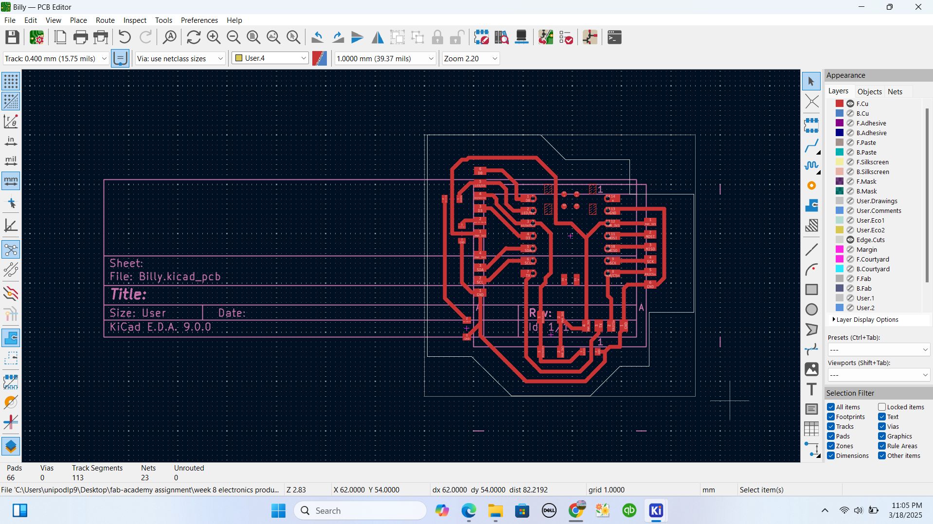
Lets continue with KICAD.
In week 6 I ended up by 3D modeling my PCB and now I' going to prepare it for printing
I get back to my PCB design in footprint part where I had 2d layer both linear layout and the lines of connections called footprint. what I had to do was to see what is needed to plot so that I can print needed parts on my PCB
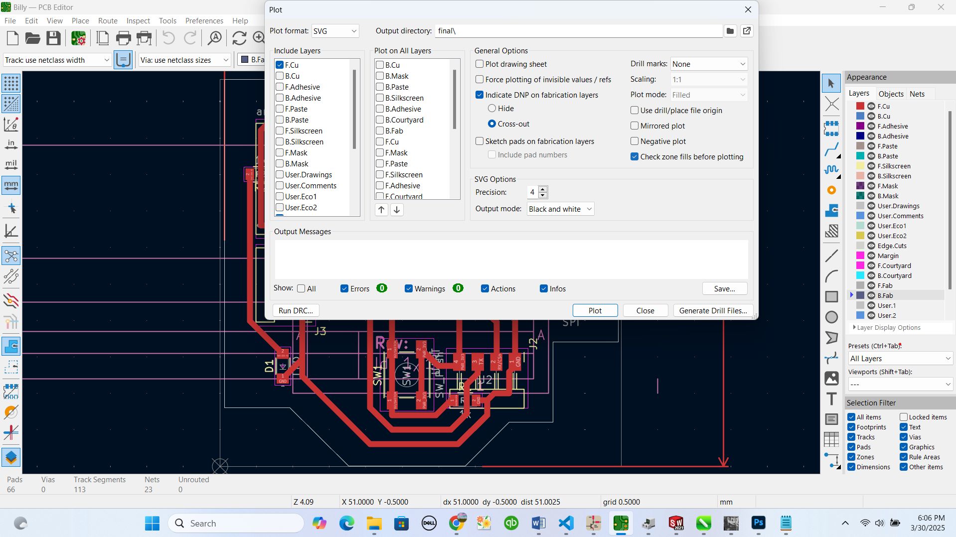
I clicked on plot icon in top navbar and it directed my to popup page telling me to define what is needed for ploting and unselect what is not needed
by here, I unselected all options and selected F.CU together with Edge.cuts which are the parts I needed on my pcb to be printed.
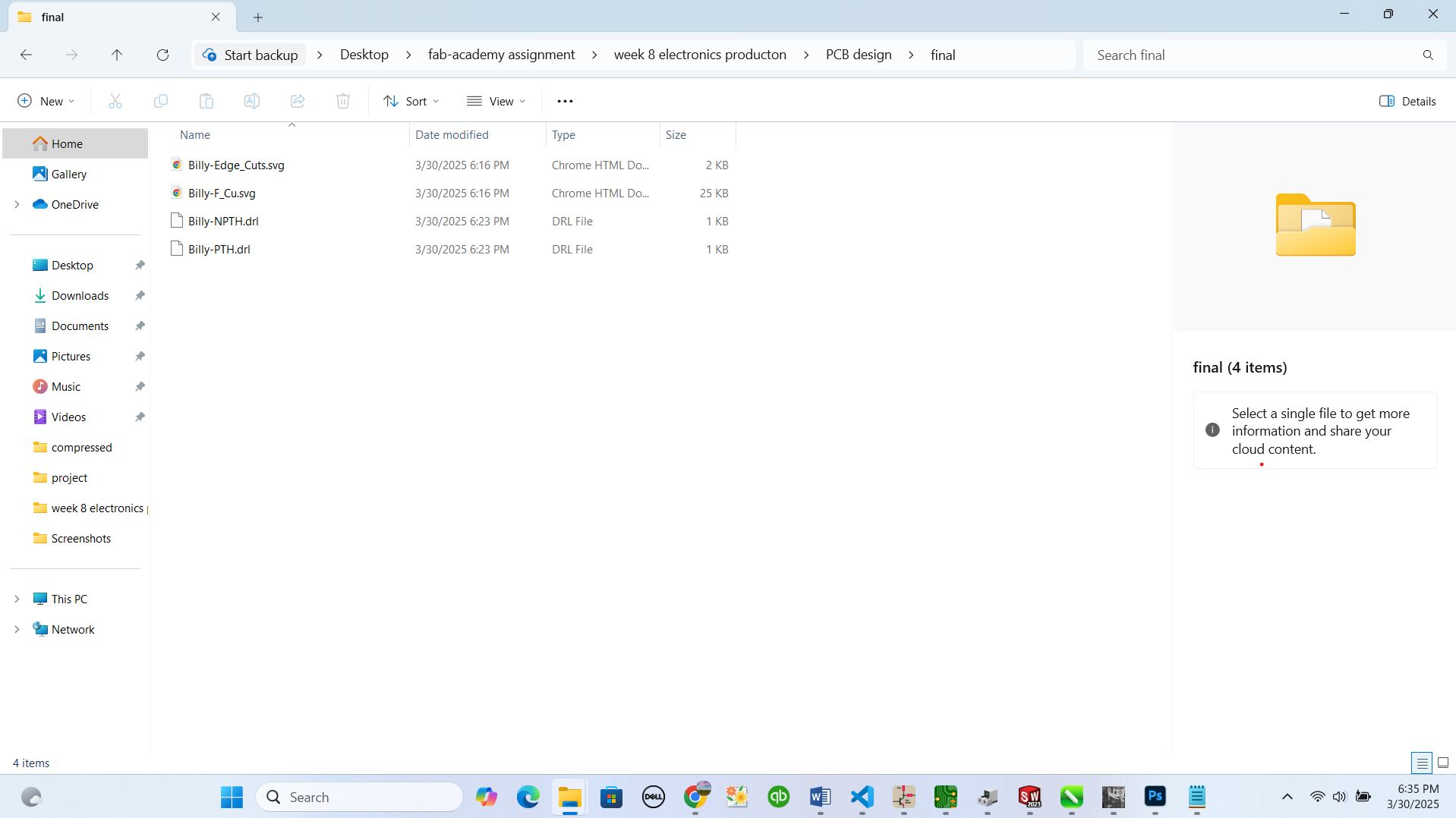
after that I clicked on Plot button then I saved the changes and file and generated the Drill files which I will be using while printing
and I was prompted to select the file format and also where to save the files
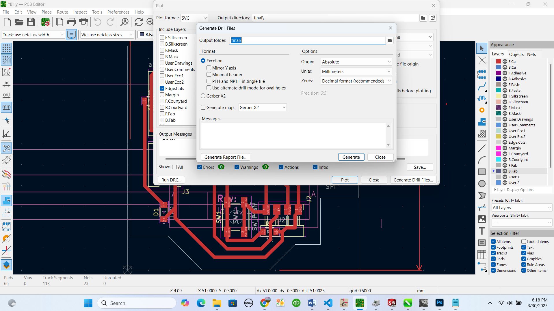
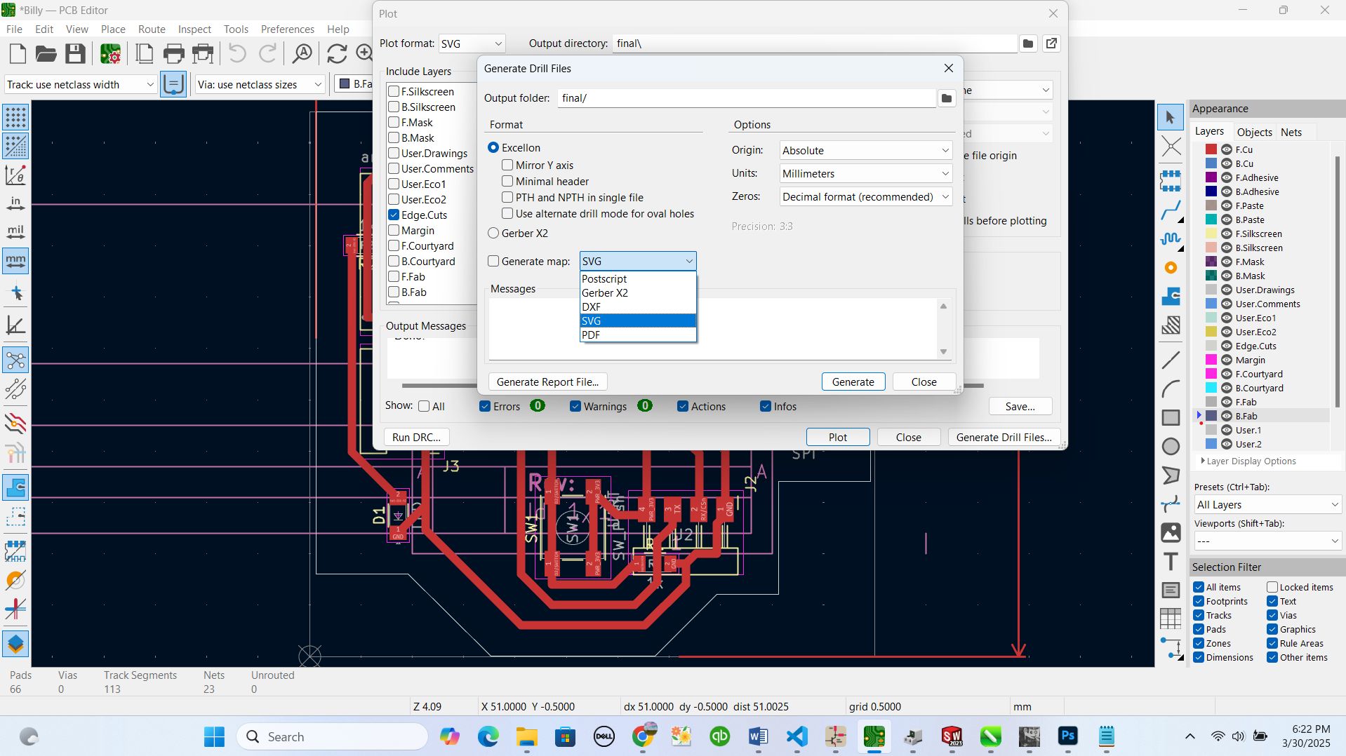
after this stage my files was ready in local storage of my computer
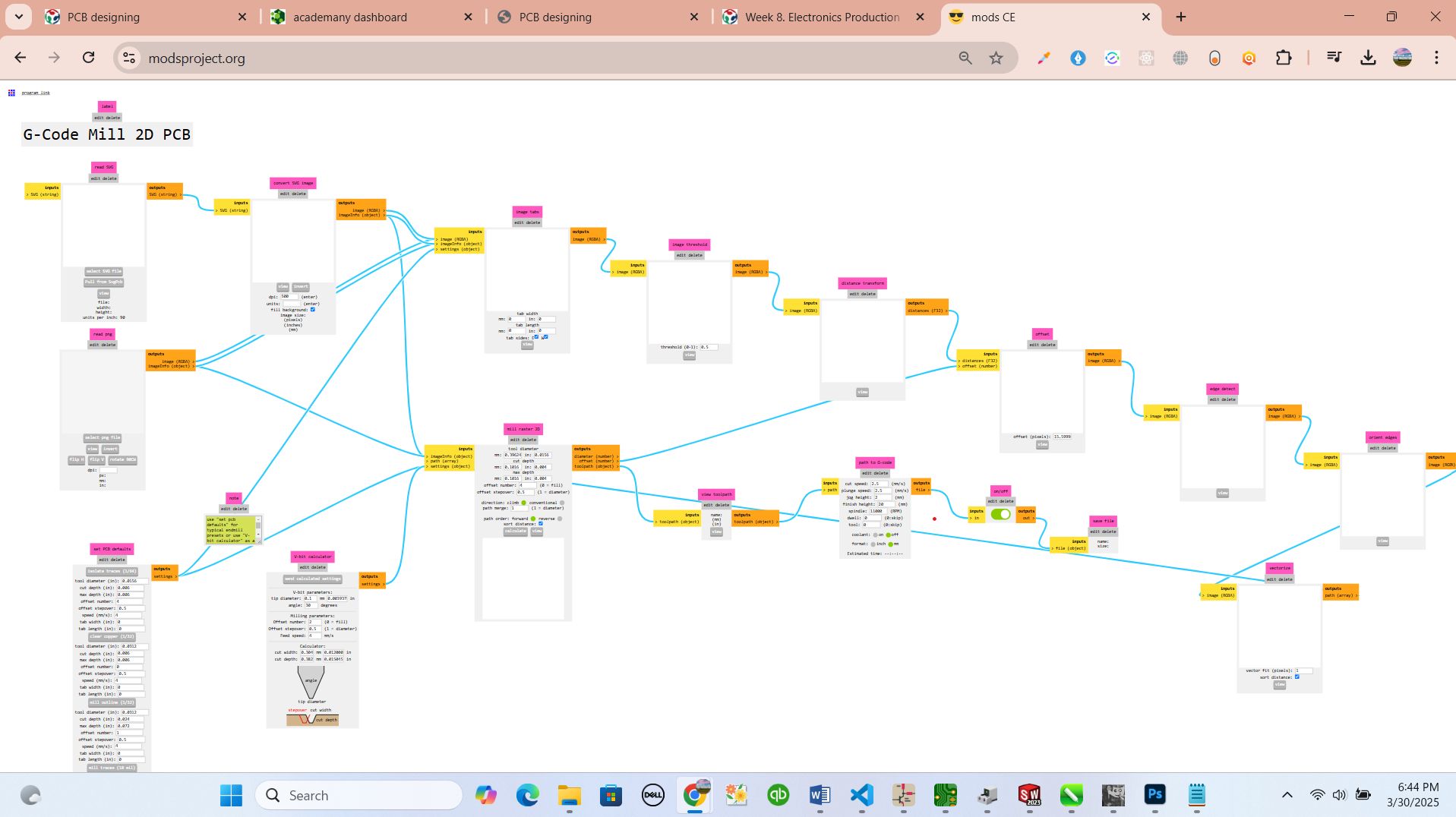
My file was ready to be converted to the g-codes where our pinter can understand the design and all plotted lines. that is the reason I joined http://modsproject.org platfom to help that job. for more info about modsproject platfom, Mods CE is a modular, cross-platform tool designed for fab labs, enabling tasks like CAD, CAM, machine control, and automation through interconnected modules. It serves as a community-driven extension of the original CBA mods research project, aiming to foster development and exchange of new modules within the community.
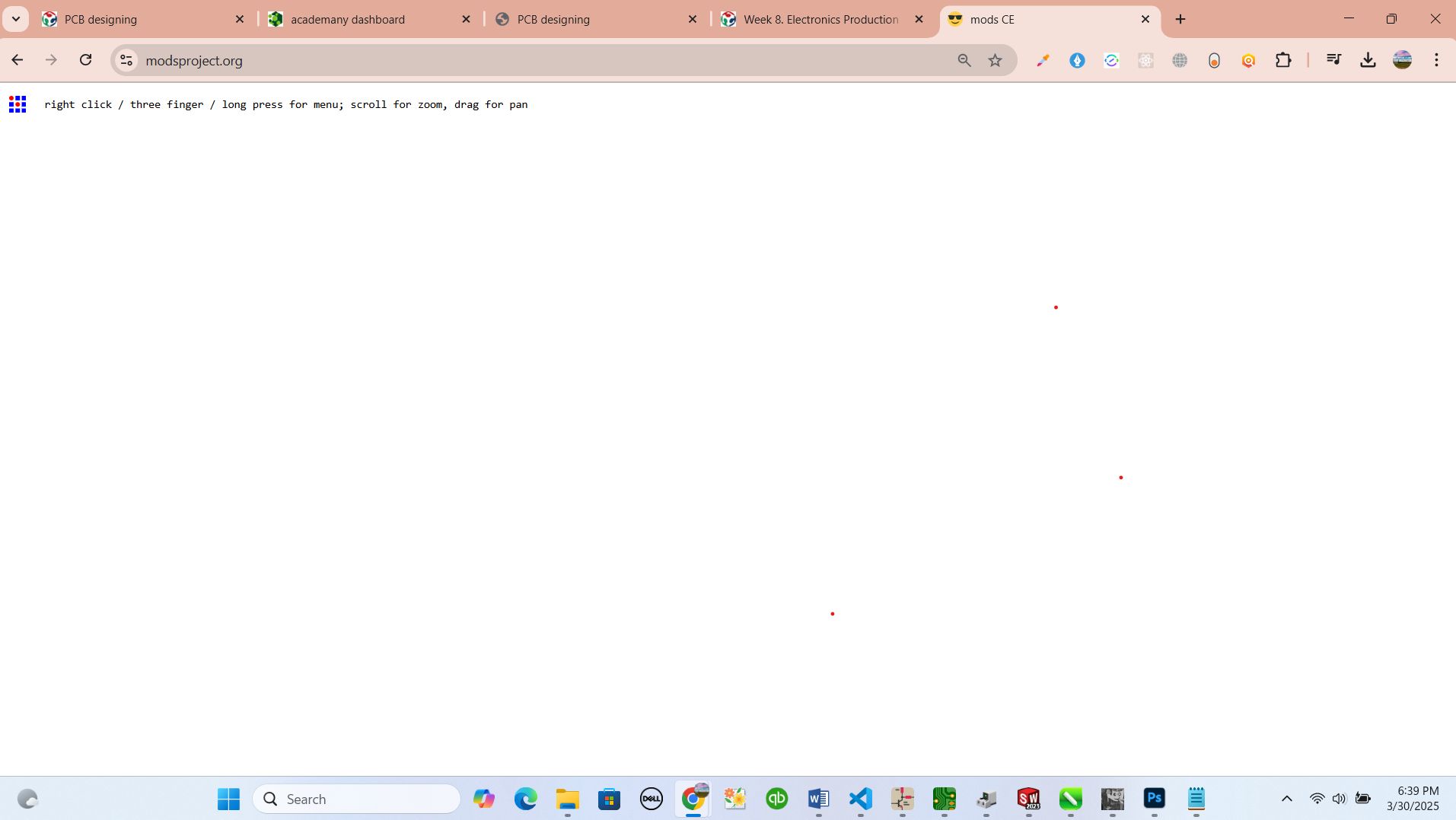
by here I right clicked on icon found in top conner and I navigated through programs and next to open programs
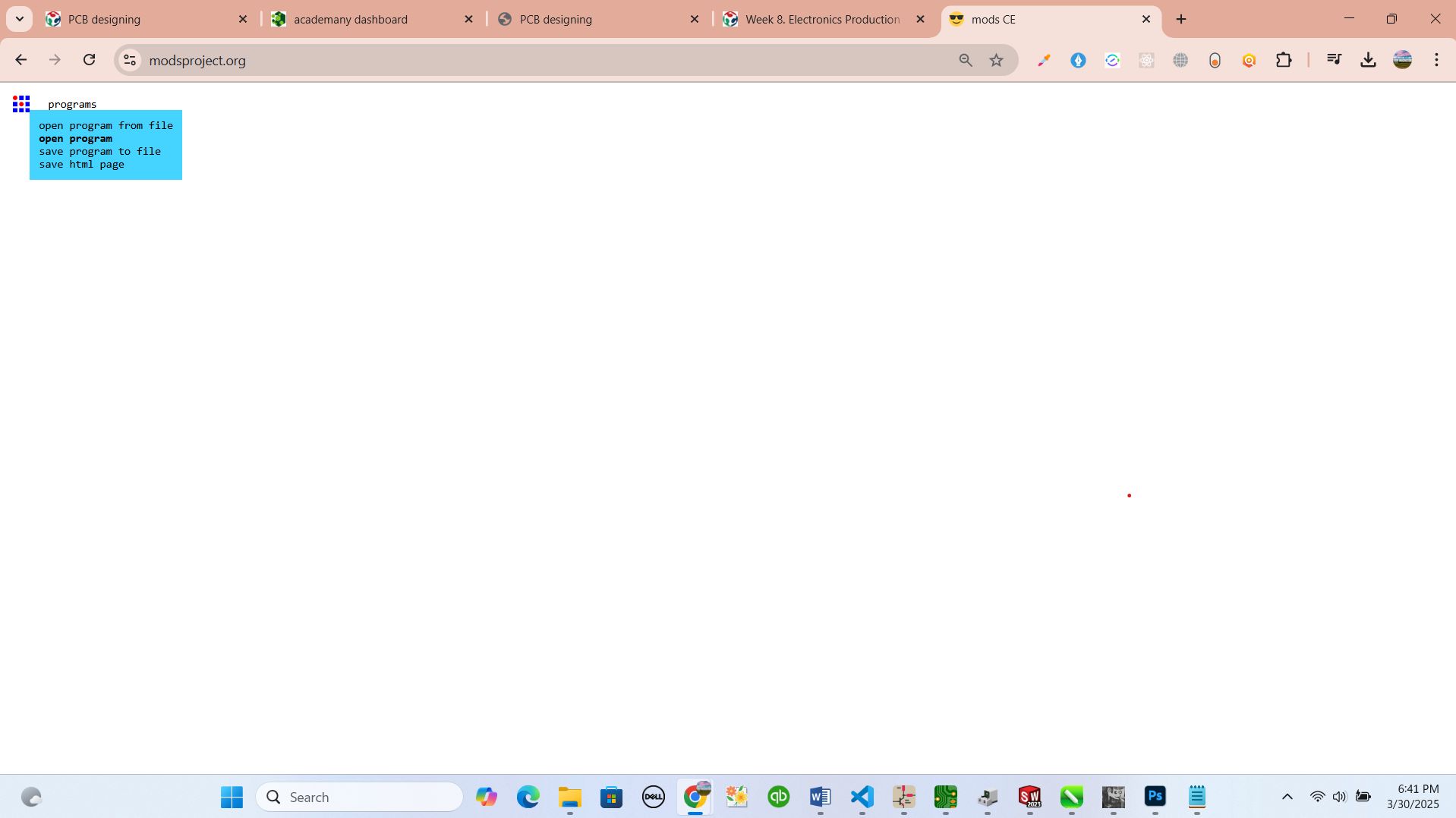
from there, I had to selecet the programs I'm going to use on my project. I selected G-CODE and navigated to mill 2D PCB
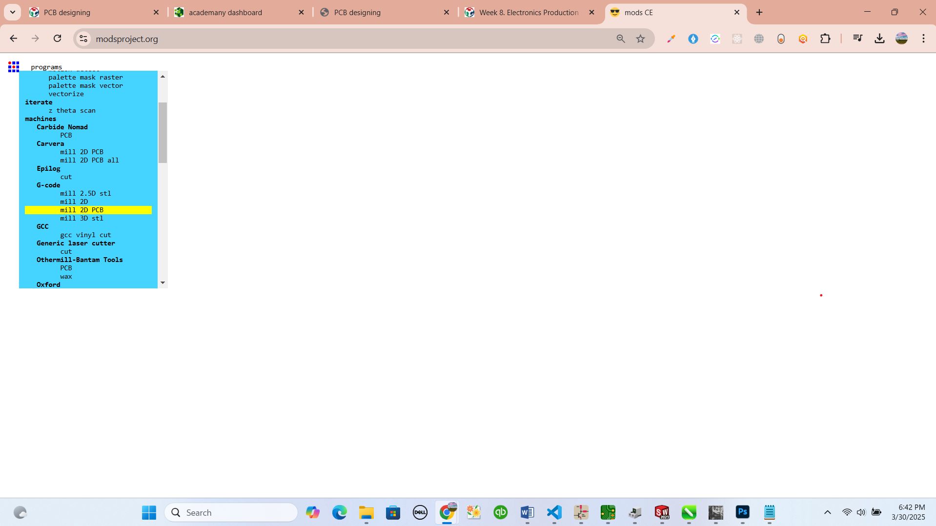
from that the link redirected me to page containing many functions and tasks to follow but what was the main is to upload the file in SVG format and follo the steps
by here, from the first table I selected the button named select svg file and I clicked on it and redirected me to local disk where I saved my svg file for printing
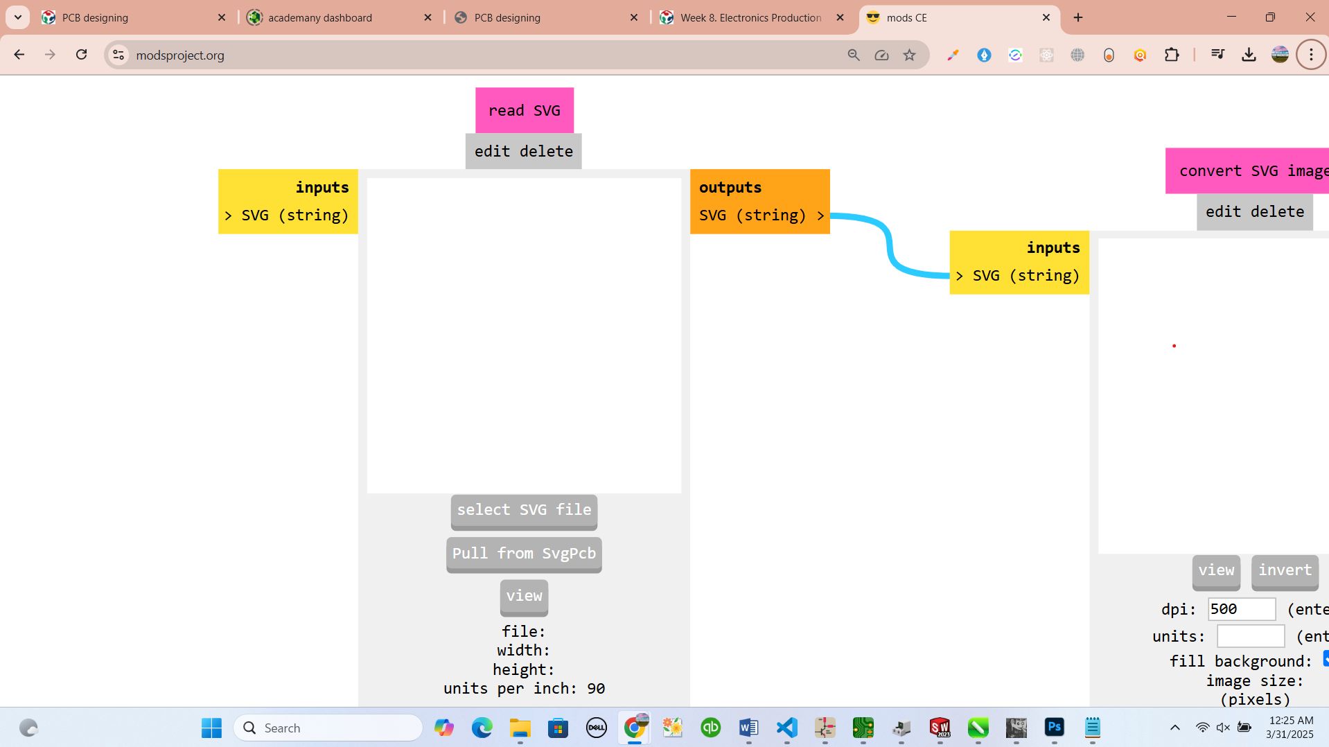
then I selected it and uploaded it to continue on next step
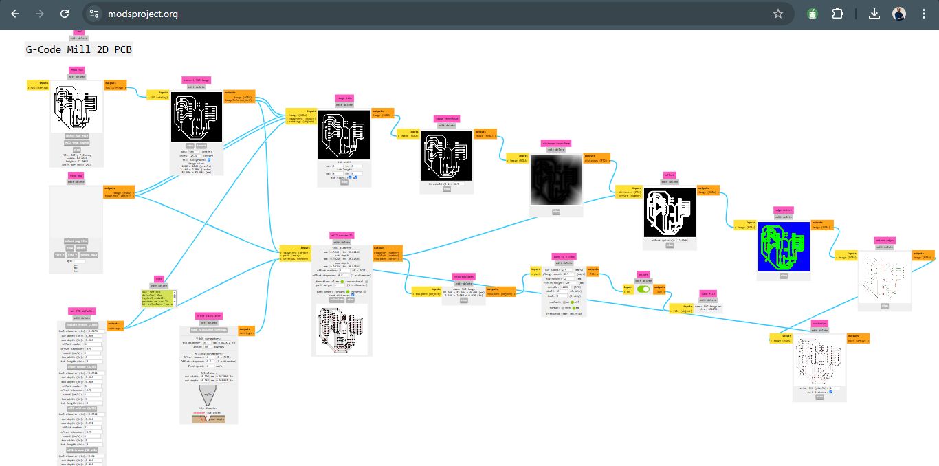
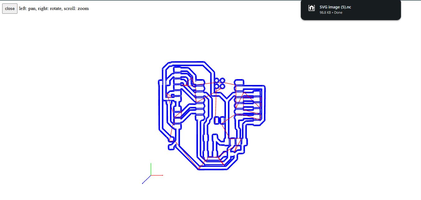
After that I set how the file should be where I inverted the way it was looking like and selected milling trace for milling type and the size. then I downloaded it as g-codes format from modsproject. then I clicked on view mode for final file
How I connected my computer to pcb printe r and how I printed
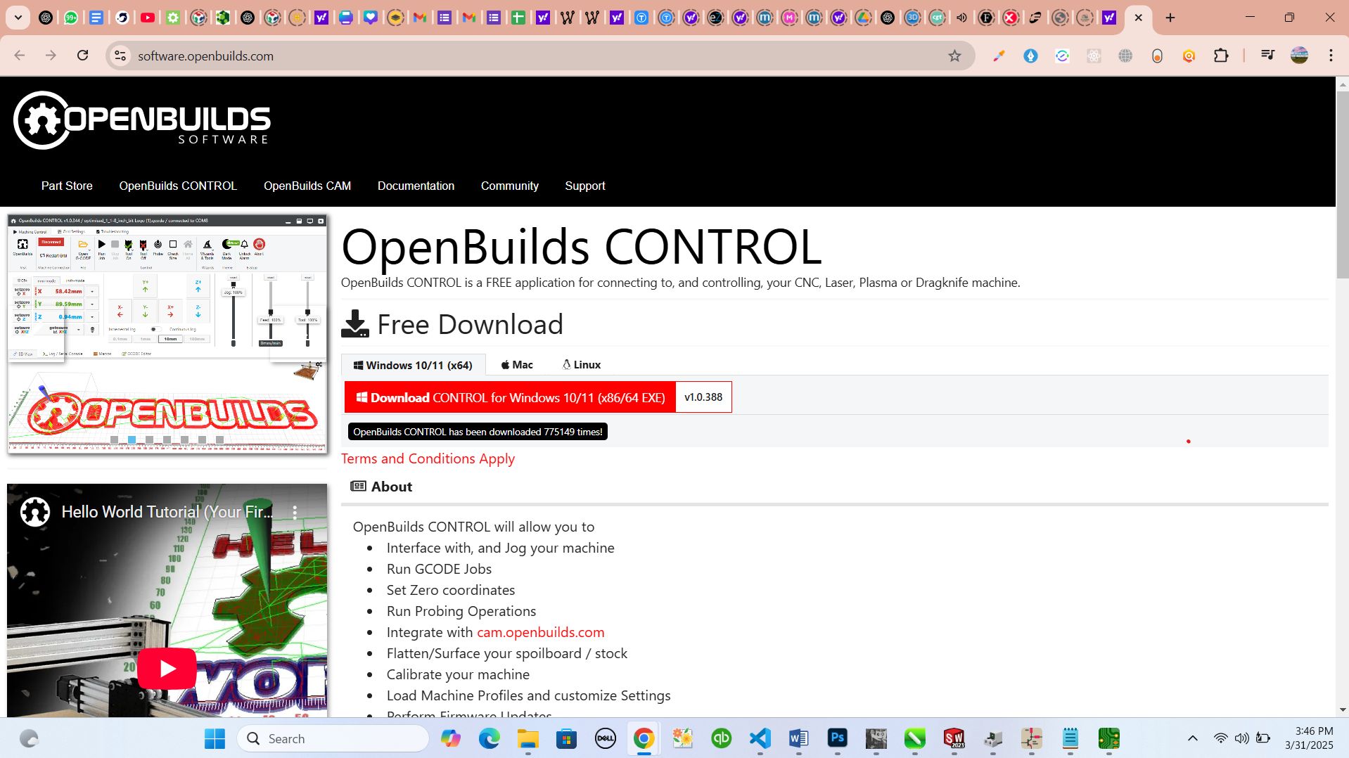
I started by donwloading openbuilds app that control different CNCs and this was going also to help on pcb printer
how I downloaded openbuilds and installation
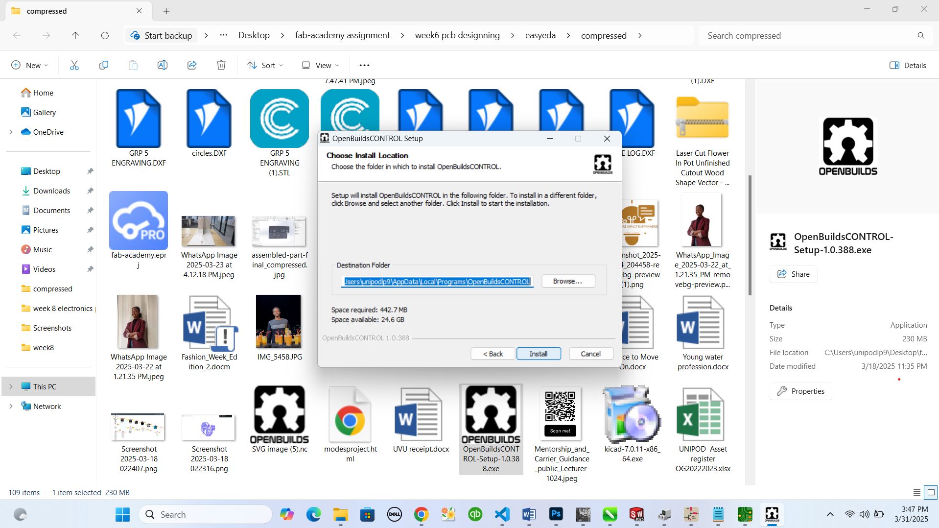
after this stage openbuilds was ready to be opened and that was my next move to open it
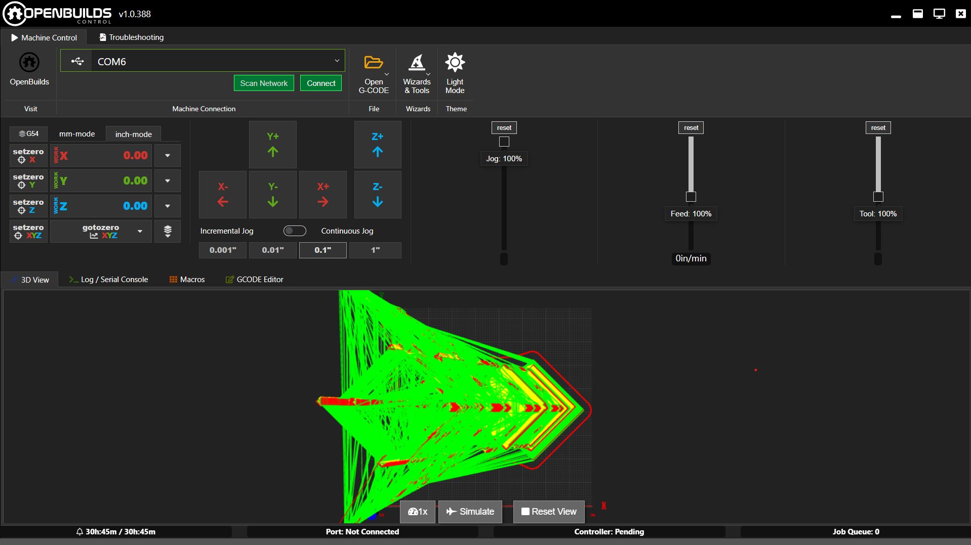
so, now I can connect my computer to pcb printer because the software to control the printer is ready and the file to use while printing is ready.
I connected my computer's port to printer via usb and it was sucessfully connected
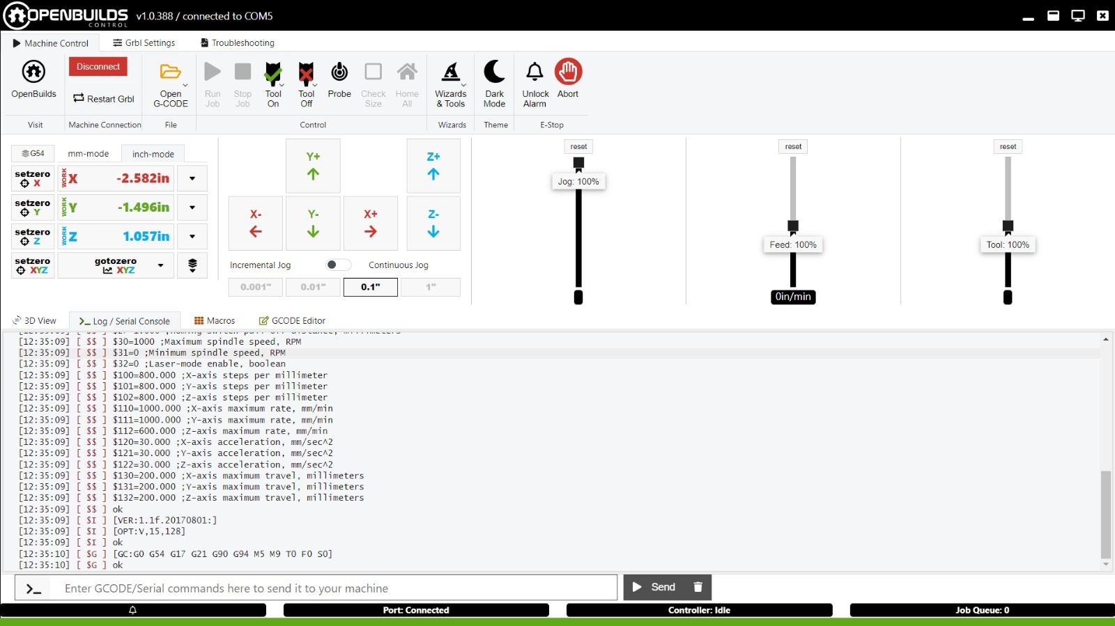
this is how I imported the file of my design to be printed, I clicked on open file and selected it from the directory
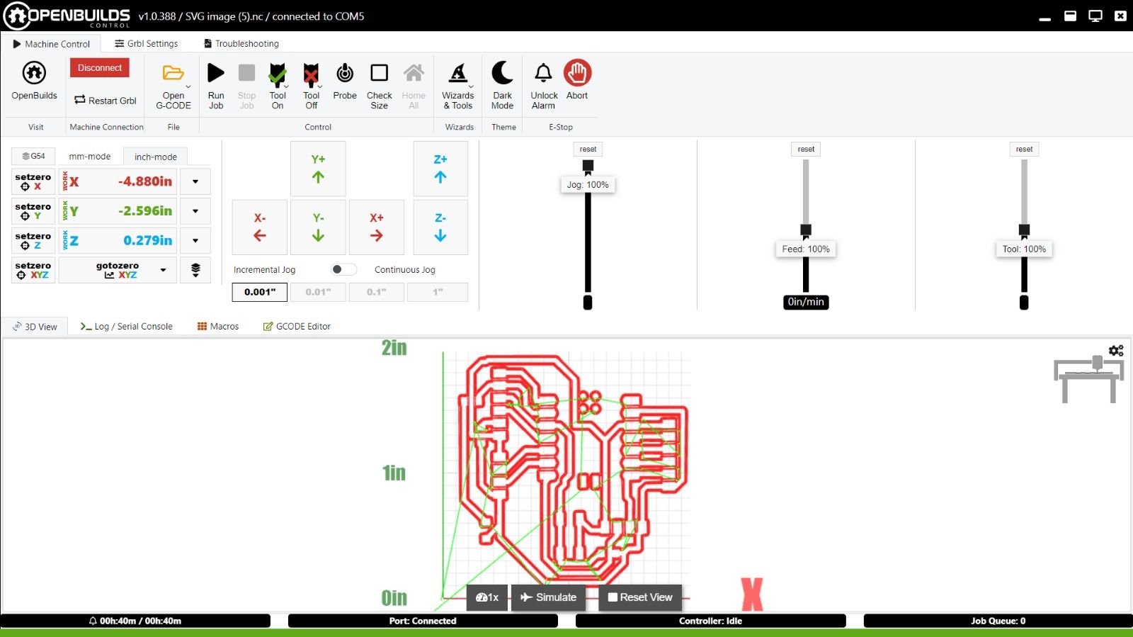
by here, I was ready to start printing but I had to set the orgin and level of my nozel to start cutting. I did it and start cutting from run job button
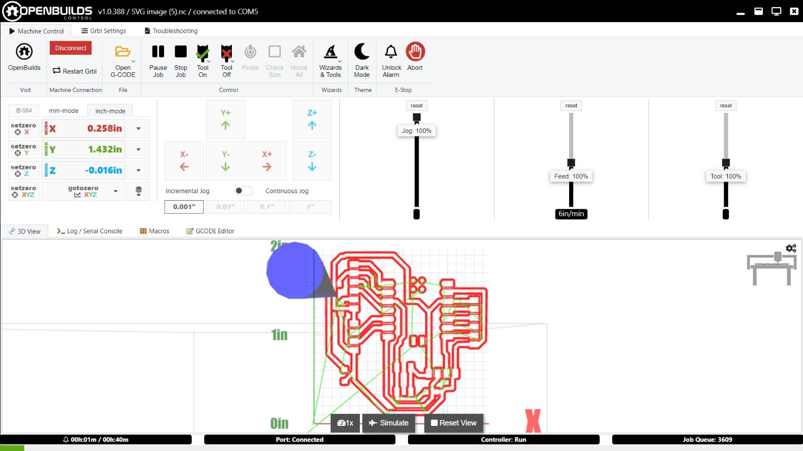
here is the video while pcb printer working on my design
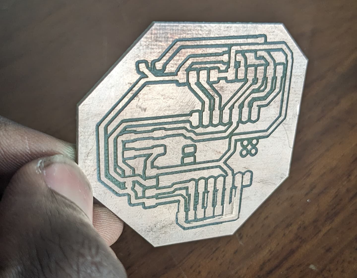
after printing here is the output from my design
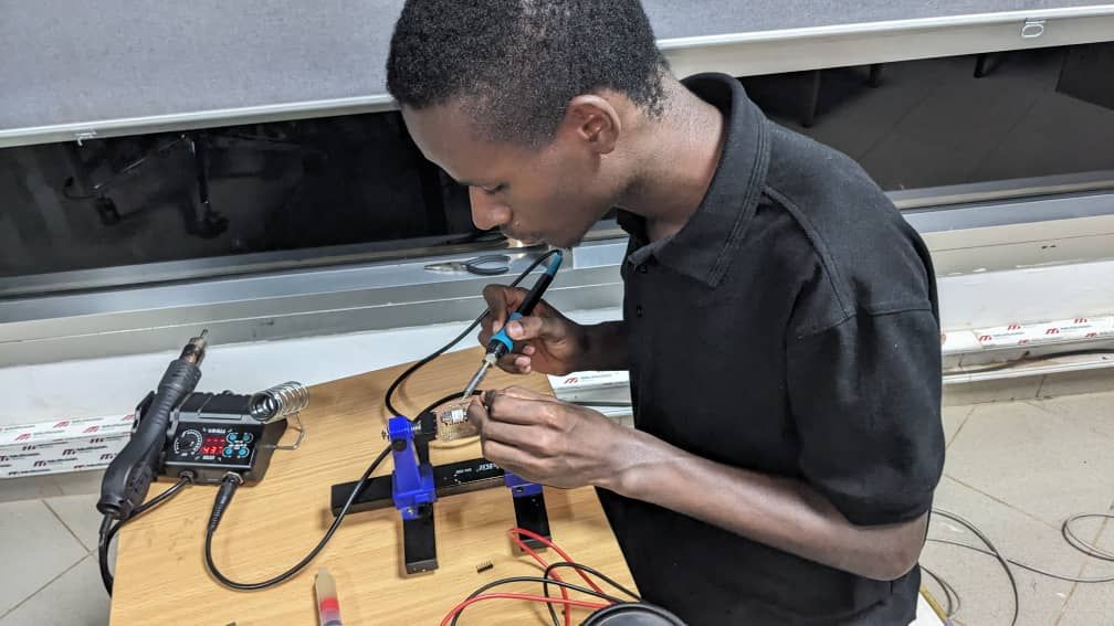
from this stage I was supposed to teest the flow of current and solder all pins and microntroller on the pcb inorder to be able to connect other devices to my pcb
this is how I prepared my pcb for soldering
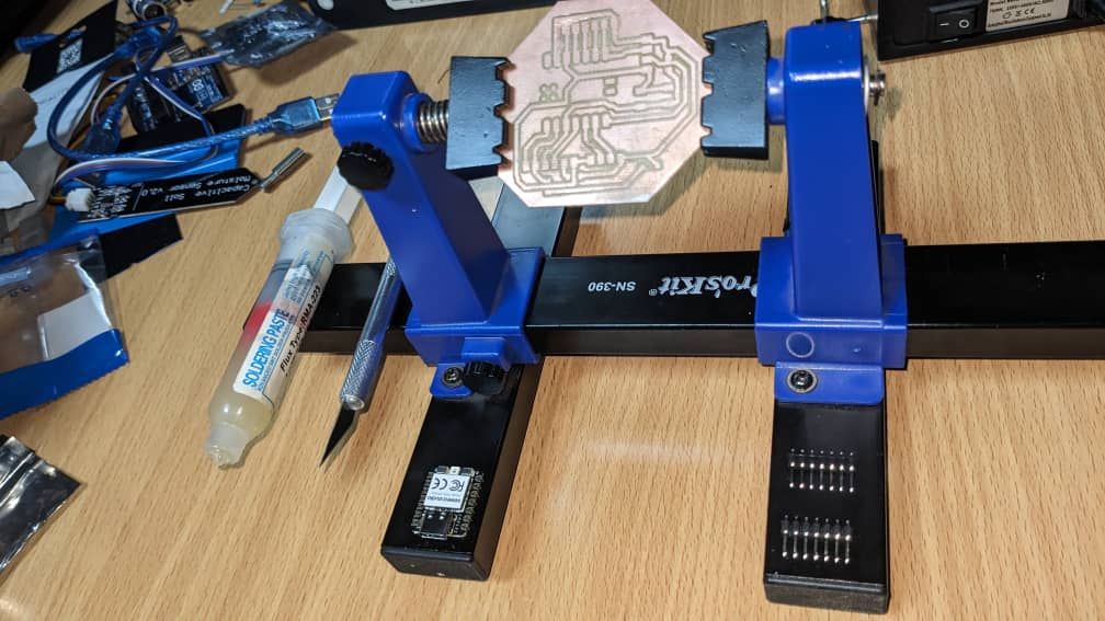
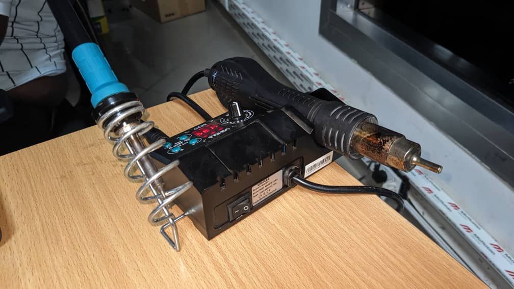
here is the soldering tool to be used while heating soldring wire
adding soldering wire on XIAO micro-controller and soldering it on my pcb
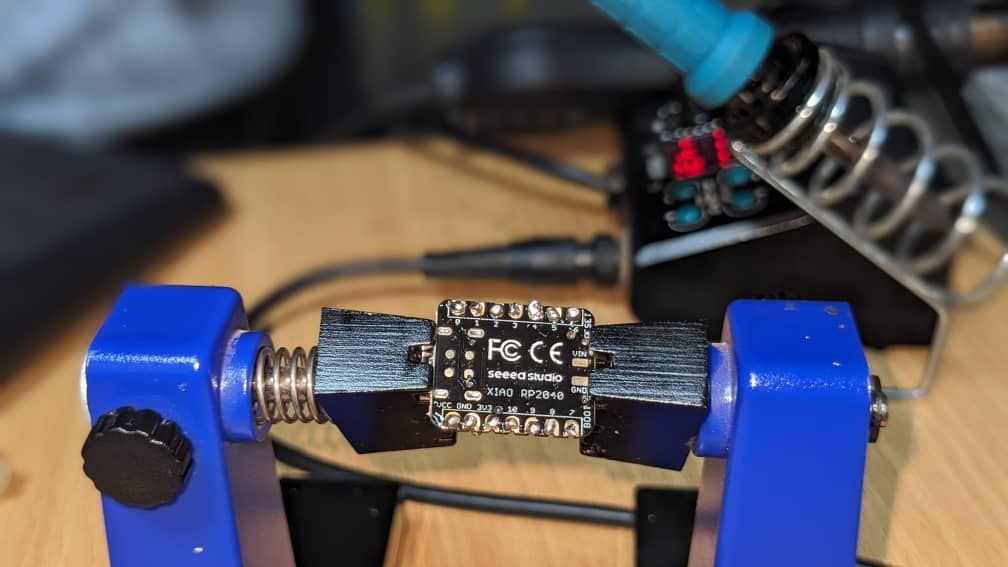
after adding micro-controller on my pcb, I added pins on pcb that will allow input and output devices to be connected on my pcb and I added also resistors and led
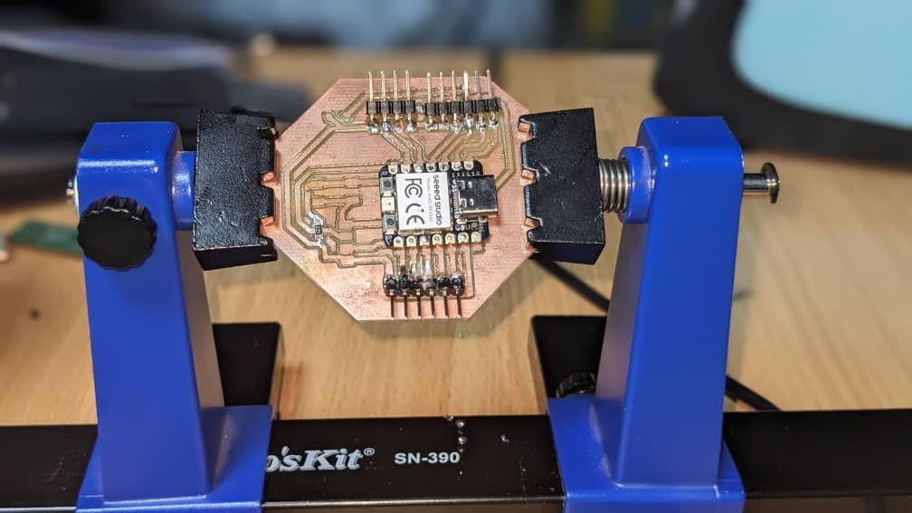
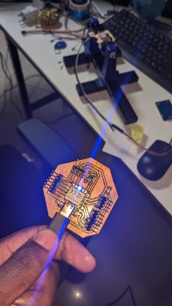
after the whole job from designing to printing and soldering, I tested my pcb by pluging in it from my computer via usb port which transfer 5v and here is the output
Here is the original files for Electronics Production
svg files and .nc file
svg files and .nc file