For this group assignment, we used the test equipment available in our lab to observe and analyze the operation of a microcontroller circuit board. Specifically, we demonstrated the use of a multimeter and an oscilloscope to measure and visualize electrical signals on the board. This process is essential for debugging, validating, and understanding the behavior of embedded systems.
                                    int led = 6;           // the PWM pin the LED is attached to
int brightness = 0;    // how bright the LED is
int fadeAmount = 1;    // how many points to fade the LED by

void setup() {
  pinMode(led, OUTPUT); // declare pwm pin to be an output:
}

void loop() {
  analogWrite(led, brightness); // set the brightness of led

  // change the brightness for next time through the loop:
  brightness = brightness + fadeAmount;

  // reverse the direction of the fading at the ends of the fade:
  if (brightness <= 0 || brightness >= 255) {
    fadeAmount = -fadeAmount;
  }
  delay(30);  // wait for 30 milliseconds to see the dimming effect
}
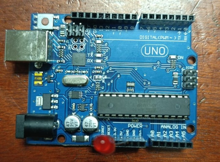
Microcontroller board prepared for testing
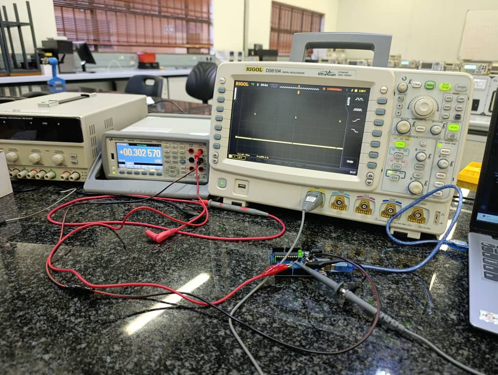
Measuring voltage and continuity with a multimeter

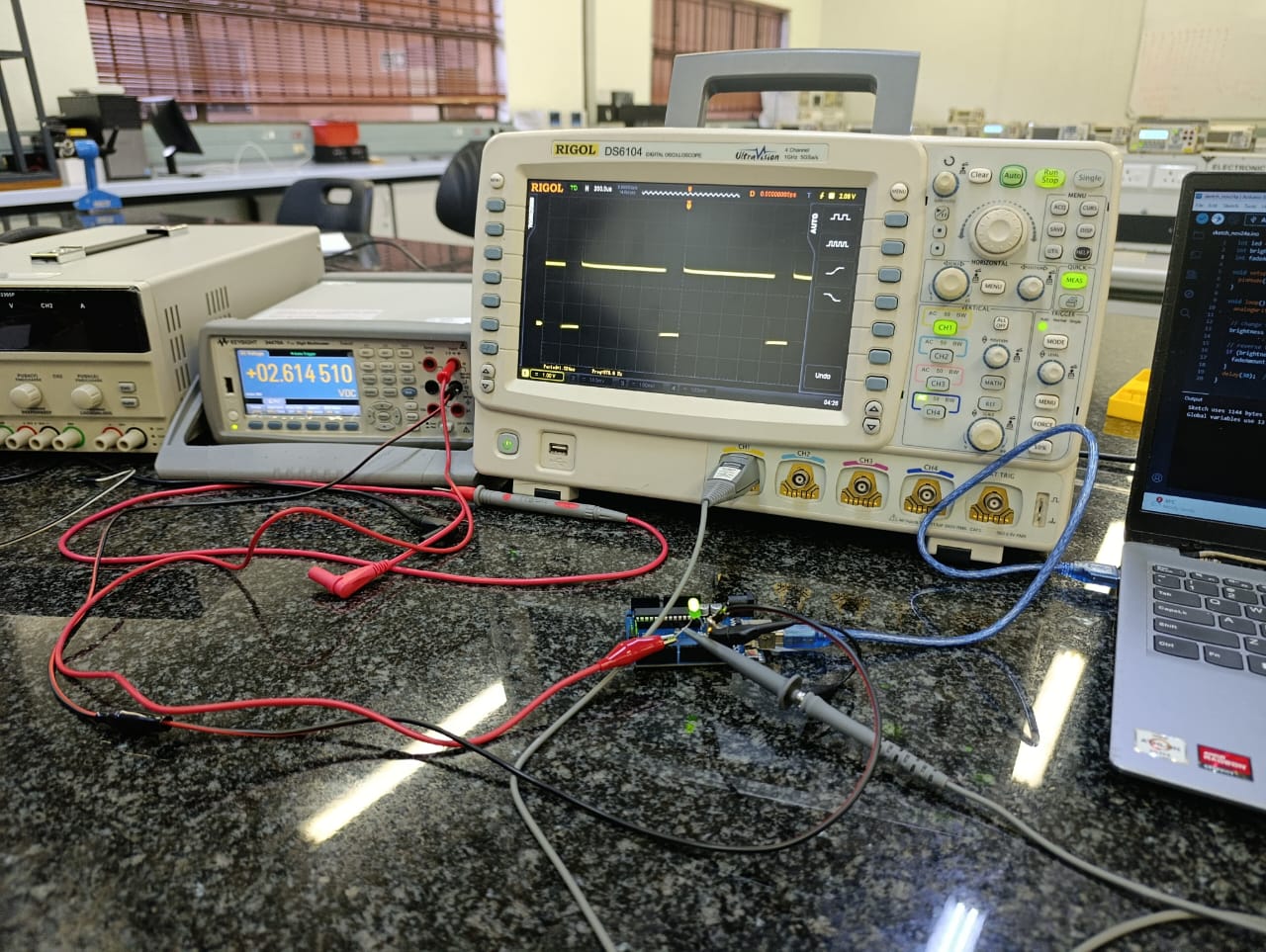
Observing PWM signal on the oscilloscope
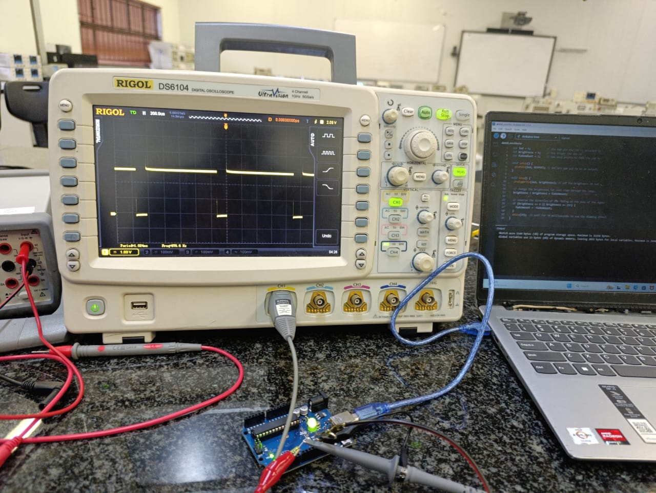
Captured PWM waveform on oscilloscope
| Test Point | Measurement | Equipment | Expected Value | Observed Value |
|---|---|---|---|---|
| VCC | Voltage | Multimeter | 5.00V | 2.614V |
| LED Pin (ON) | Voltage | Multimeter | ~5V | 2.614 |
| PWM Output | Frequency | Oscilloscope | 976 Hz | 976 Hz |
| PWM Output | Duty Cycle | Oscilloscope | 50% | 49.8% |
By using both the multimeter and oscilloscope, we were able to verify the correct operation of the microcontroller board. The multimeter confirmed proper supply voltage and signal toggling, while the oscilloscope allowed us to visualize and measure the timing characteristics of the PWM output. These tools are essential for diagnosing issues, validating designs, and gaining deeper insight into embedded electronic systems.