Assignment Brief:
- As a group review the safety data sheets (SDS) for each molding and casting material,
make and compare test casts, and compare different mold-making processes.
- Design a mold for your chosen process, produce it with a smooth surface finish hiding toolpaths, and
use it for casting parts.
- Extra credit: create a mold with more than two parts.
Materials & Manufacturing
This week's assignment focused on learning different methods of molding and casting.
With this assignment, I intended to explore and understand the following key processes and techniques:
I started with learning how various materials, especially metals and plastics, are processed using
molding, casting, machining, 3D printing, and welding — each method selected based on the material’s
properties and the final product's requirements.
Metals Processing:
- Casting — Molten metal is poured into molds to create complex and heavy parts such as engine blocks,
tools, and machinery components. I also referred to the below video to learn more. Refer to the
here: Casting Types
- Sheet Metal Forming — Thin metal sheets are bent, stamped, or drawn into products like automotive
panels, enclosures, and appliances.
- Forging — Metals are deformed under high pressure to manufacture strong components like shafts,
gears, and aerospace parts.
- Machining — Precision cutting and shaping of metals using lathes, mills, drills, and CNC machines to
create engine components and custom metal parts.
- 3D Printing (Metals) — Building complex and precise metal parts using selective laser melting and
electron beam melting, typically used for aerospace and medical applications.
- Welding — Joining metal parts by fusing them using processes like MIG, TIG, arc, and spot welding,
commonly used in pipelines, structures, and vehicles.
Plastics Processing:
- Injection Molding — Forming complex plastic shapes (like toys and automotive parts) by injecting
molten plastic into a mold.
- Blow Molding — Producing hollow plastic objects such as bottles, containers, and fuel tanks by
inflating heated plastic into a mold.
- Rotational Molding — Creating large hollow products like tanks and playground equipment by rotating
and heating plastic inside molds.
- Extrusion — Forming continuous plastic products like pipes, sheets, and films by pushing melted
plastic through a die.
- Thermoforming — Heating plastic sheets until pliable and molding them over a form to create trays,
packaging, and disposable items.
- 3D Printing (Plastics) — Fabricating plastic parts layer-by-layer for prototypes, customized
designs, and intricate geometries.
I also referred to the below video to learn more. Refer to the here:
Plastic Moulding processes
Test Moulding and casting
To start with, I came across 3 new terminologies, 1) Master Mold (also called Master Model), 2)
Mother Mold and 3) Draft angle.
Master Mold/Model- The original object you want to copy. Can be made by any material (3D print,
clay, wax). This is to create the first mold.
Mother Mold- The rigid shell that supports a soft mold. Can be made by plaster, fiberglass, resin
and this made is to prevent deformation during casting.
Draft angle- A draft angle is a slight taper (usually 1–3°) added to the vertical
walls of a mold to allow easy removal of the cast part without damaging it.
For my molding and casting project, I began by testing different types of mold-making techniques to
better understand material behavior and mold quality. My initial goal was to create a sphere mold as
a test object, because a sphere has continuous curves and can reveal imperfections clearly during
casting.
To begin, I designed and fabricated two different master molds using two distinct methods: Bamboo Labs 3D
printing and wax milling. I undertook this to understand the differences in layer resolution and surface
finish between the two techniques.
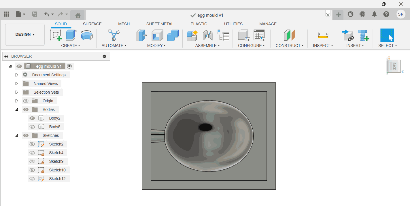
Design Process
Firsty I began with a sphere mold as a test object, because a sphere has continuous curves and can reveal
imperfections
clearly during casting. Later, over having a converstaion with my Lab instructor I learnt that
having an
egg shaped mould will help test impurities better. As the oval shapes helps give a direct link to
the exact eroor in the design or the part of fault unlike a perfect sphere would give. This would
also help us dig into
learning on casting over more complex shapes
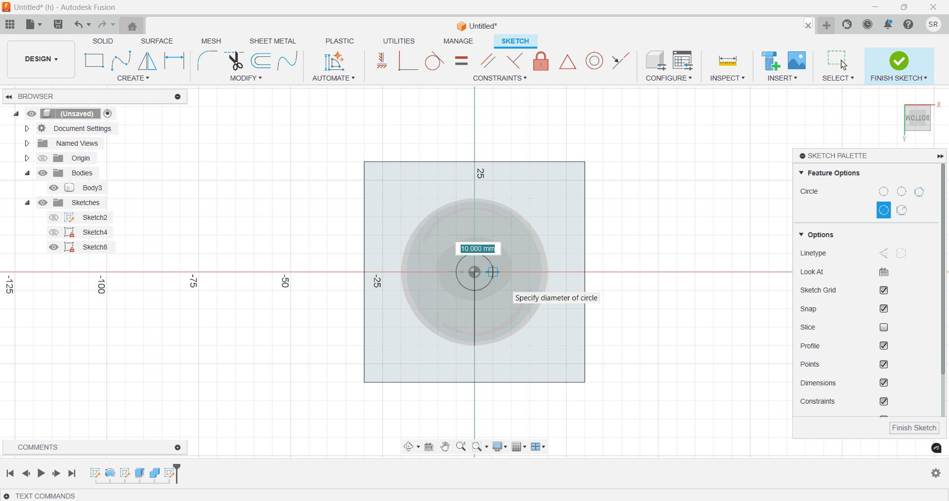
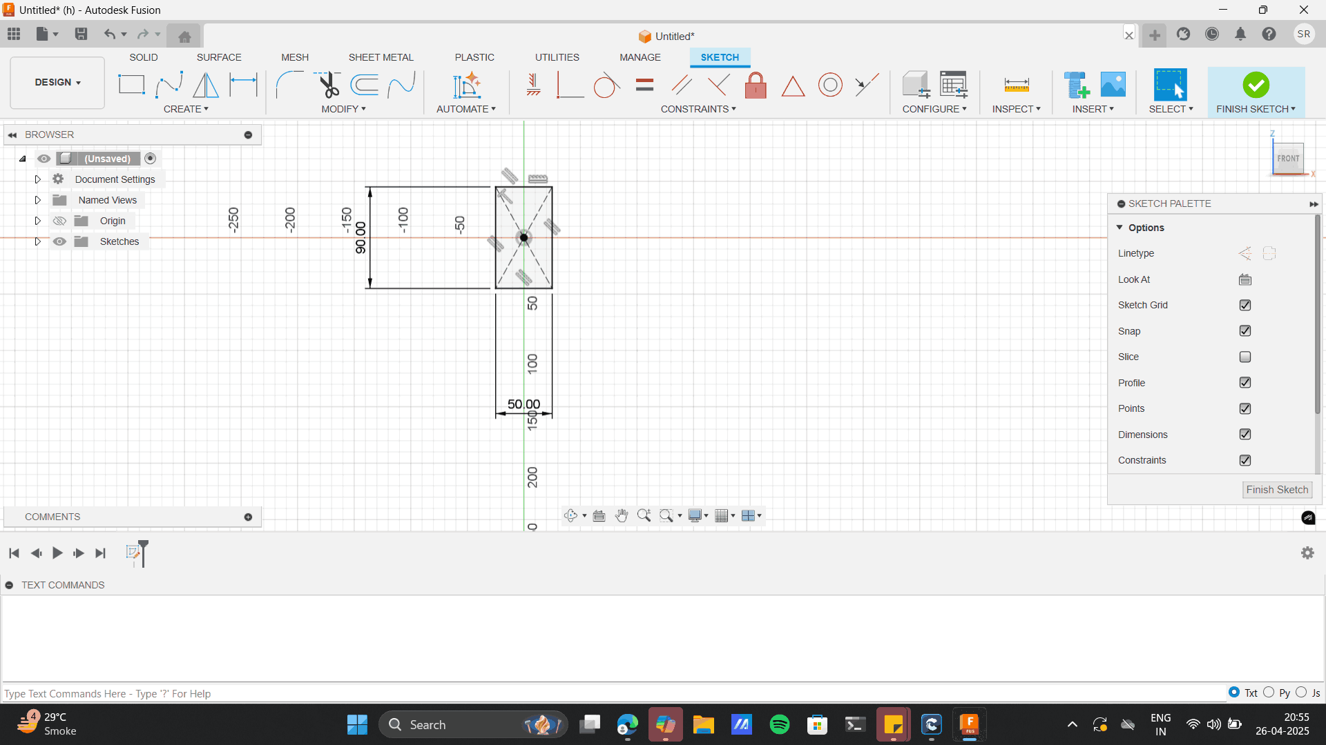
Create an elipse + a centre line> Use trim tool to Trim half of the elipse to get a
semicircular elipse.
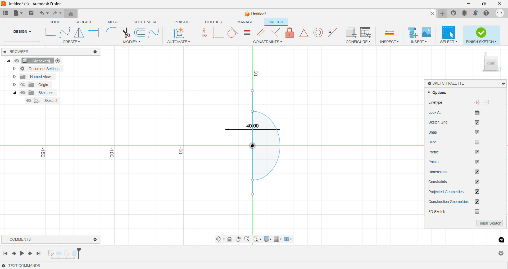
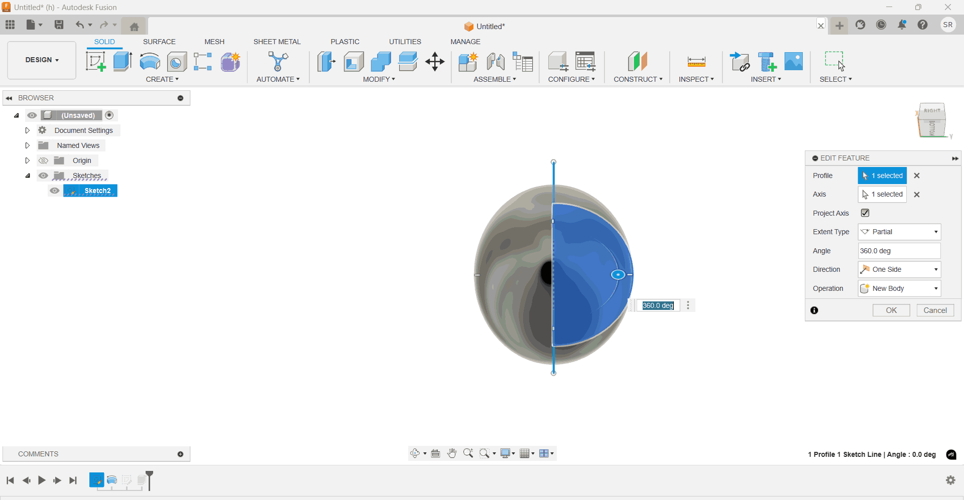
Finish sketch> Use revolve tool to revolve the semi circle elipse around the centre line.
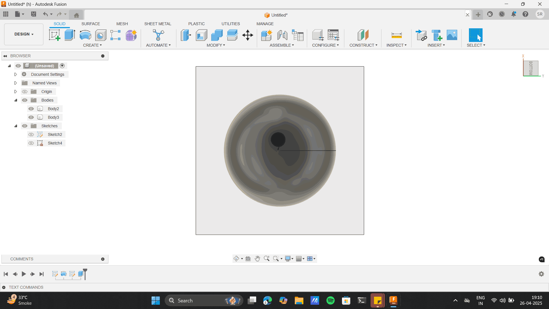
From the centre plan pf the oval, create a rectangle around the Oval sphere and extrude in
symmetry.
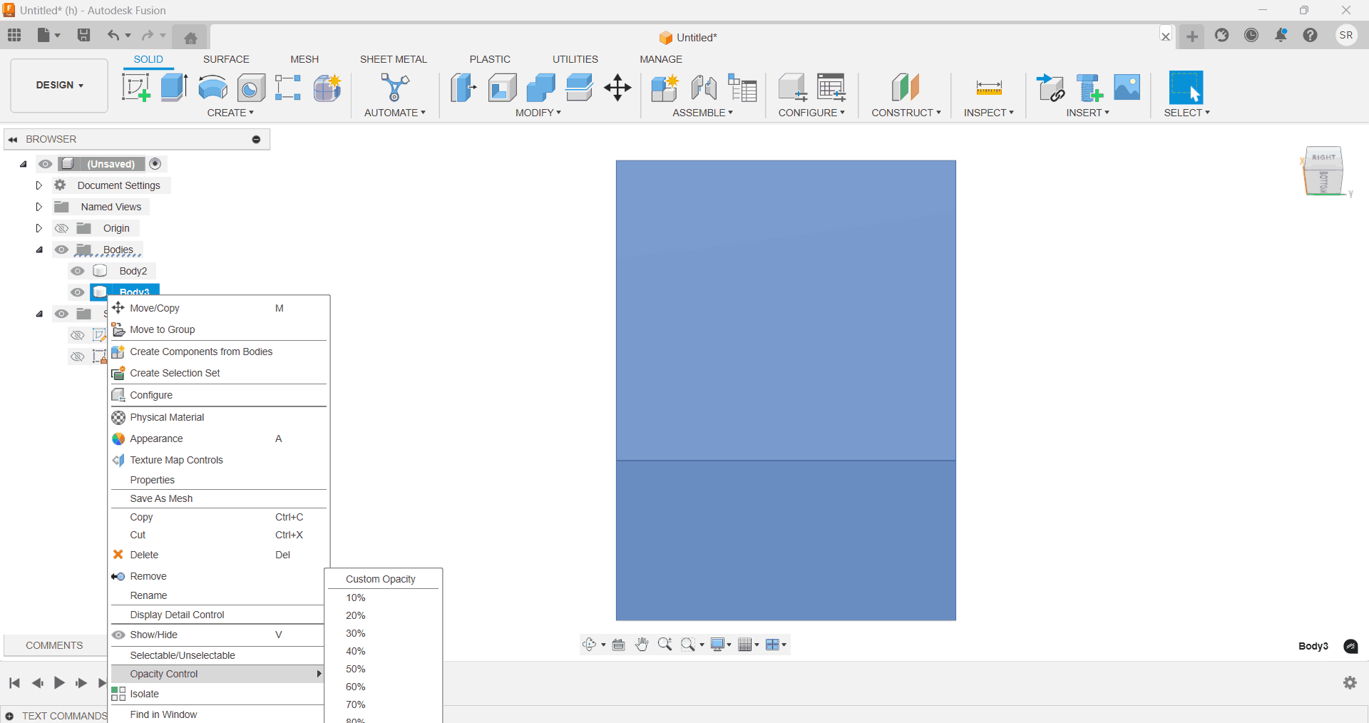
Change the opacity of the rectangle around the oval sphere to see thought the rectangle body,
by right-clicking over the body and chnaging opacity controls.
Here comes the interesting part of creating the Master Mold of our egg shell.
Select the combine tool> Target body- outer cuboid> Tool body- centre egg.
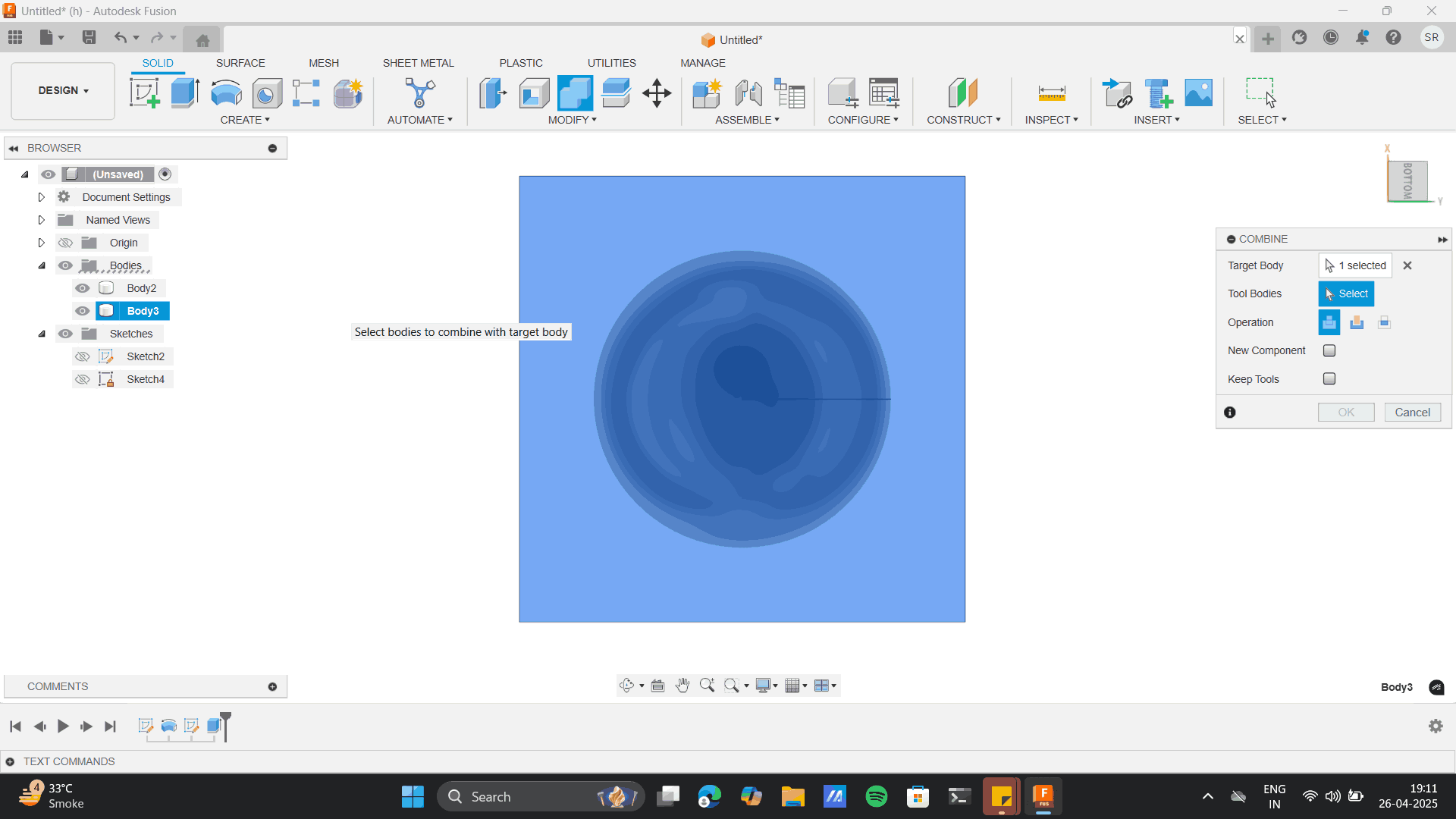
As you do this, most importantly in the operation- select operation of cut through, And the
Egg cut off the cuboid at its perfect location.
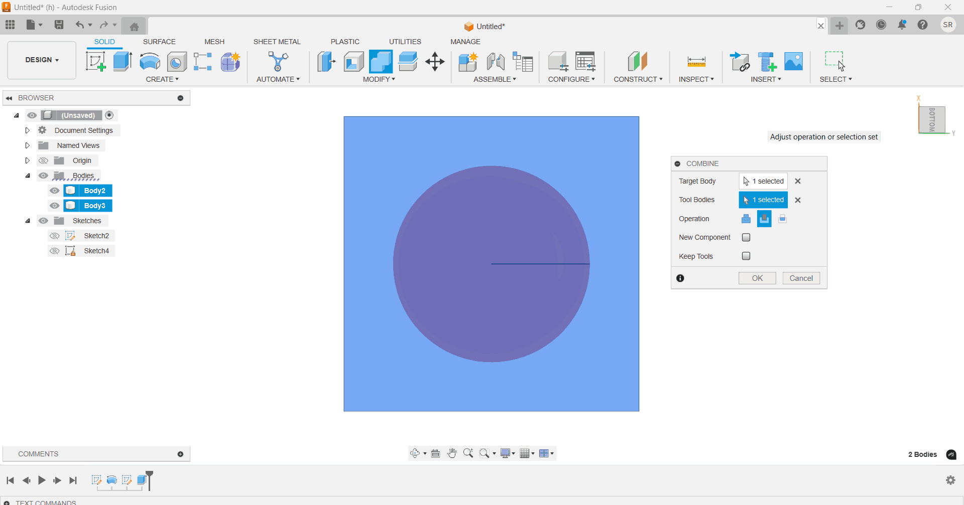
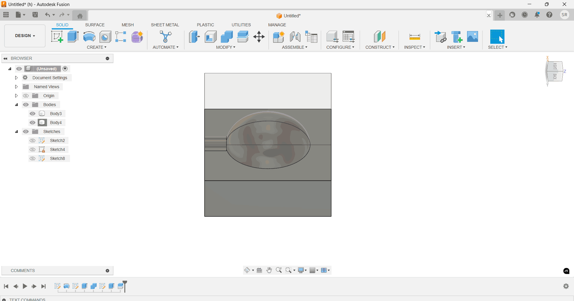
Learning: From the above process I made a cuboidal casing for our silicon mother mould and I split
the overall mould into two halves are I desired.
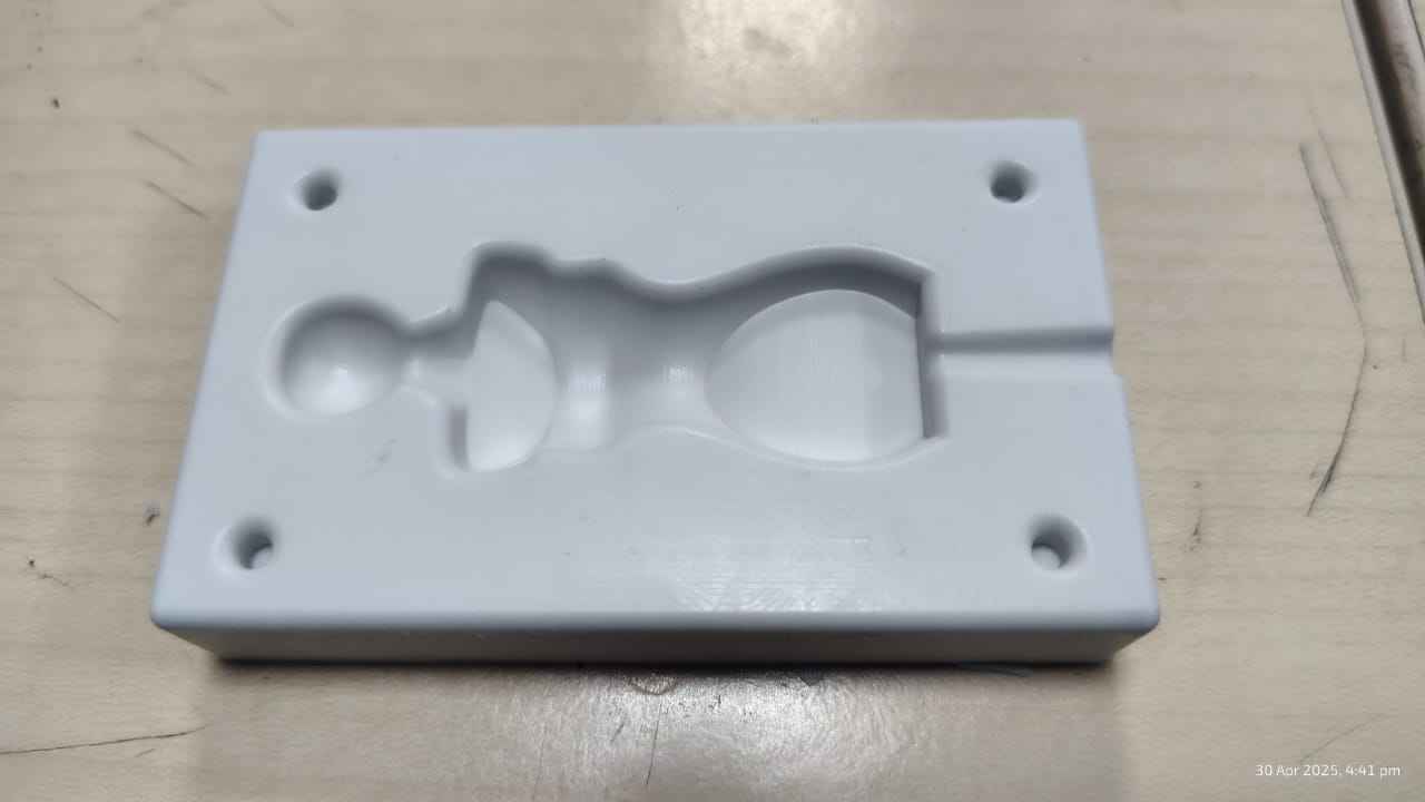
In the next stage of the process, I created a trail body that connects the edge
of the cuboid to the oval shape. This step is crucial as it will form a hollow path in the master
mold (or silicone mold), which will serve as the channel for pouring the casting material. The
hollow path ensures that the material flows smoothly into all sections of the mold. At the same
time, the trail body also creates a pouring tube in the mother mold (or resin mold), which will be
used to pour the resin or casting material into the mold.
I created a trail body that starts connects the edge
of the cuboid to the oval shape.
Also, a key learning was to taper the pouring section as we come to the the oval as clearing
of the
pouring layer from the casting is very simpler.
Now Select both the bodies> Split tool> Use centre plane as the splitting tool.
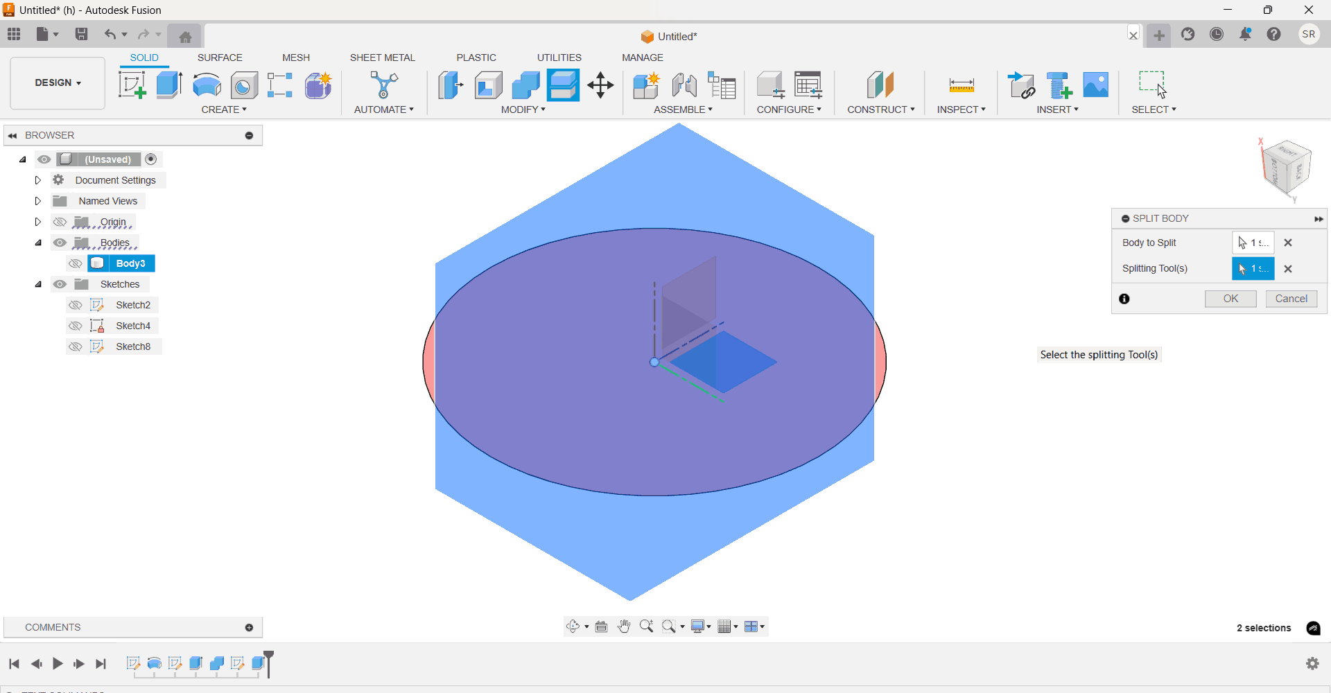
This gives us a two Separate moulds.
Note: Use the middle plane as the slitting tool only when you hav designed with reference to the
origin.
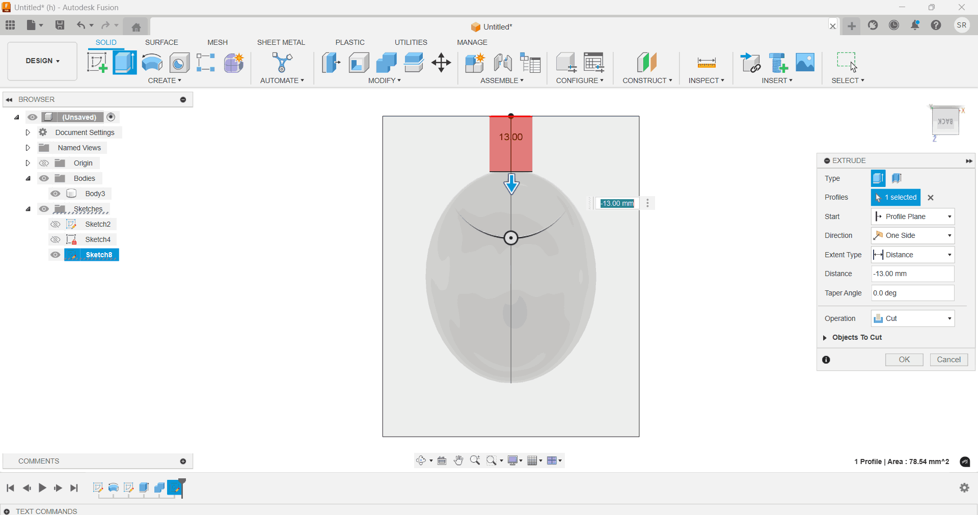
Learning 2: From the aobe model hide the half side of the total modl and for the remaining half
extrude cut the overall block
height to 20mm from the egg body and give a rectangular closure to the top surface. Finally we get
the Master mould for our
Sphere.
I designed and fabricated the above master mould using three different methods:
An egg shape with Bamboo Labs 3D printing (FDM)
A teddy bear using SLA printing
A mannequin through wax milling.
FDM 3D printing mould
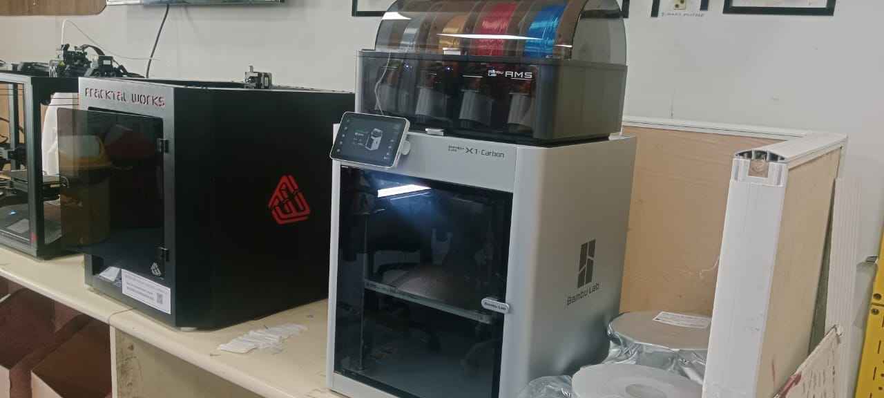
Bamboo Labs 3D Printing:
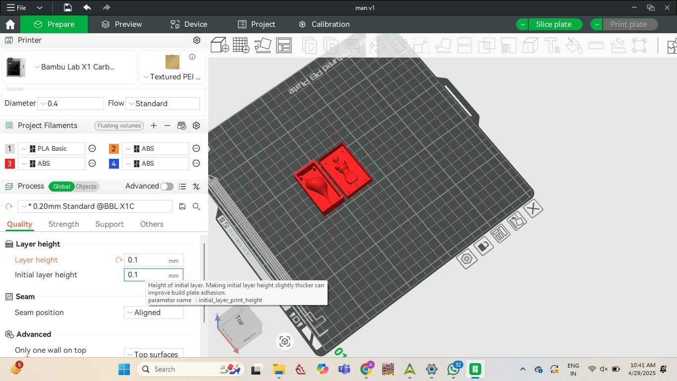
I created the first mold by 3D printing a sphere model using a Bamboo Labs 3D printer. This
method allowed for precise detail and complex geometry, but I was also aware that the layered
texture typical of FDM 3D prints might affect the surface finish of the cast. I specificallt used
the layer height as 0.1 mm to get a smoother surface.
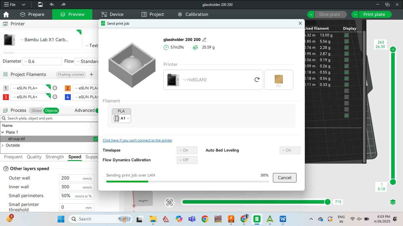
Bamboo Labs.
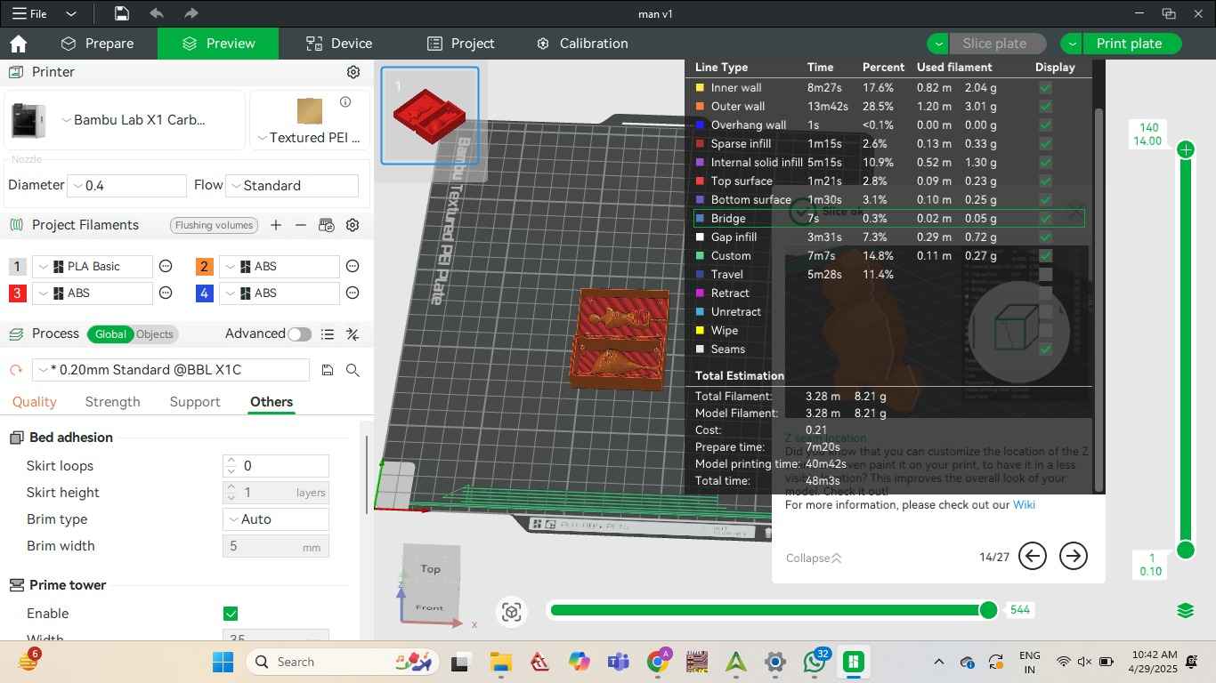
Print job prepared and sliced, ready to be sent to the Bamboo Lab printer.
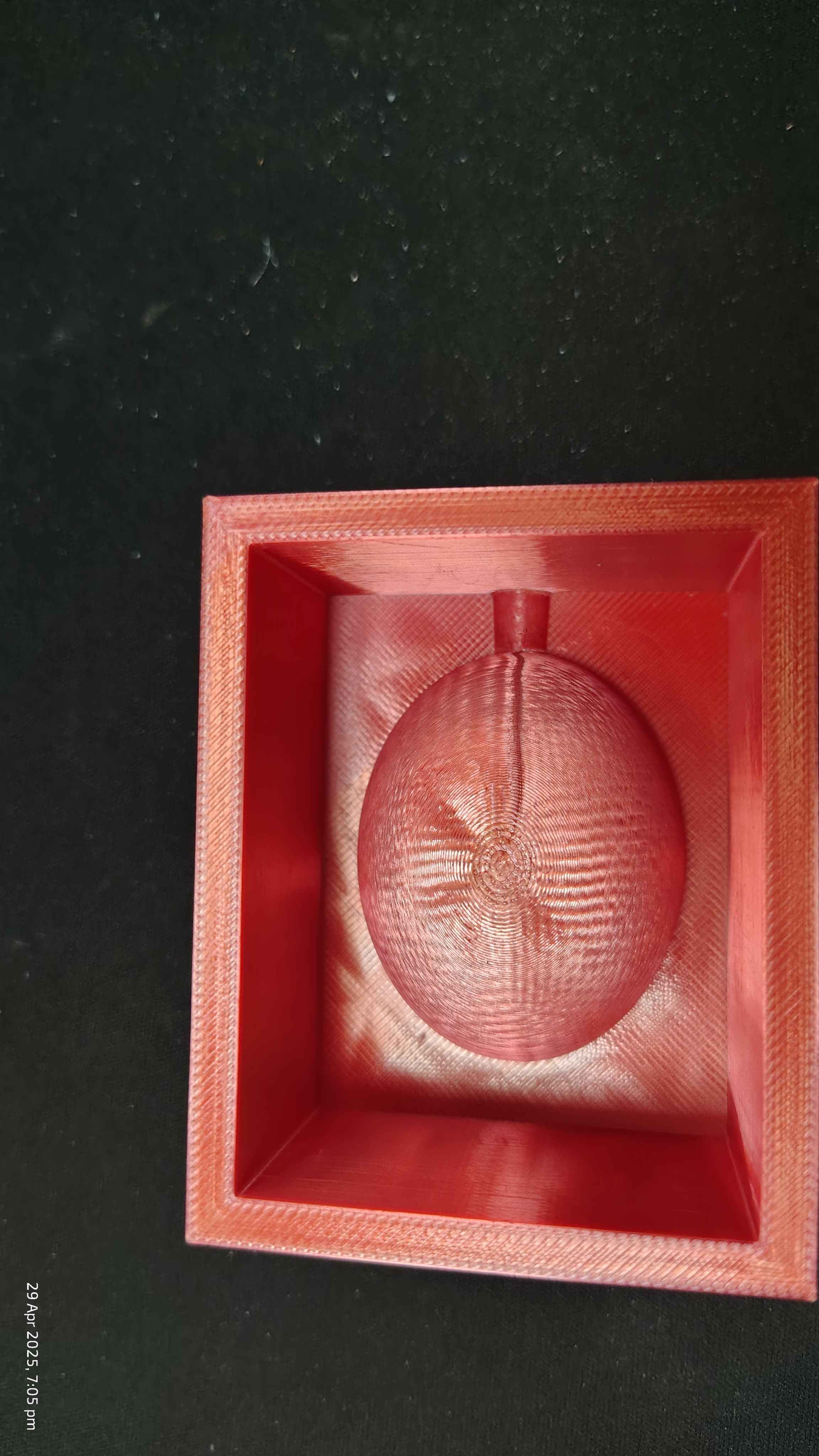
This the Finish I aquired on 3d printing.
SLA Resing Mould
Similarly, referring to my Seniors documentation, Himanshi Jain
I referred to my her documentation and learnt that she had done her moulding in on SLA printing . I
just wanted to test the output of the layer from every possible way so I used the same mould which
she had created . To know more of the She build a Build a mould of teddy
bear On SLA this was again to test the Silicone mould smoothness. To learn the proper procedure of
mould designing and casting refer to her documentationhere.
Wax Milling: Manequinne Design
Draw a rectangle with the origin in its centre.
Now from the top layer draw 9 parallel lines with the rectangular pattern to form a grid.
.png)
Draw the above half head shape using line tool.
.png)
Draw a Circle at the centre as neck.
.png)
In the same manner draw the whole mannequin like curves in the grid.
.png)
Draw a centre line throughout the whole body and finish sketch.
.png)
Now use the Revolve tool, with the centre line as the axis
and form the neck and head.
.png)
We need a plane Perpendicular to the body so draw a plan at three points.
.png)
Then, draw a plan at an angle
.png)
Offset the planes at parallel verticle grids throught the body.
.png)
Offset planes. Note to keep the planes a coincide with the verticle gride lines.
.png)
Draw a Rectangle on each plane and offset the planes.
.png)
This form a cuboid around the mannequin.
.png)
Now on the Top layer select the sketch lyaers of the grid other than of the mannequine.
.png)
Use the revolve tool, around the centre axis line> Operation: CUT
.png)
As the model was formed I thought the neck was very fragile. So I used the loft tool on surfaces to
form a stronger neck region.
.png)
Wow! Manequinne ready.
.png)
Now, Just as we did for the Egg shell, split the body in two halves.
.png)
Split the body and form a rectangle box around one of the split parts.
.png)
Around the body build circular cylinders that would help in binding two moulds.
.png)
Last but not the least, developing the slit for the pouring of the cast.
.png)
Draw the circle on the outer shell casing.
Use the trim tool cut of the extra part from the circle that is not on the cuboid.
.png)
Extruded towards the mannequin body and taper by 0.3 degrees.
.png)
Final wax mould.
.png)
Milling Wax
Wax Milling:
For the second mold, I milled a sphere out of wax using a CNC milling machine. Wax milling
provided a smoother finish and more accurate curves compared to 3D printing, but it was a more
time-consuming process requiring careful toolpath planning and milling setup.
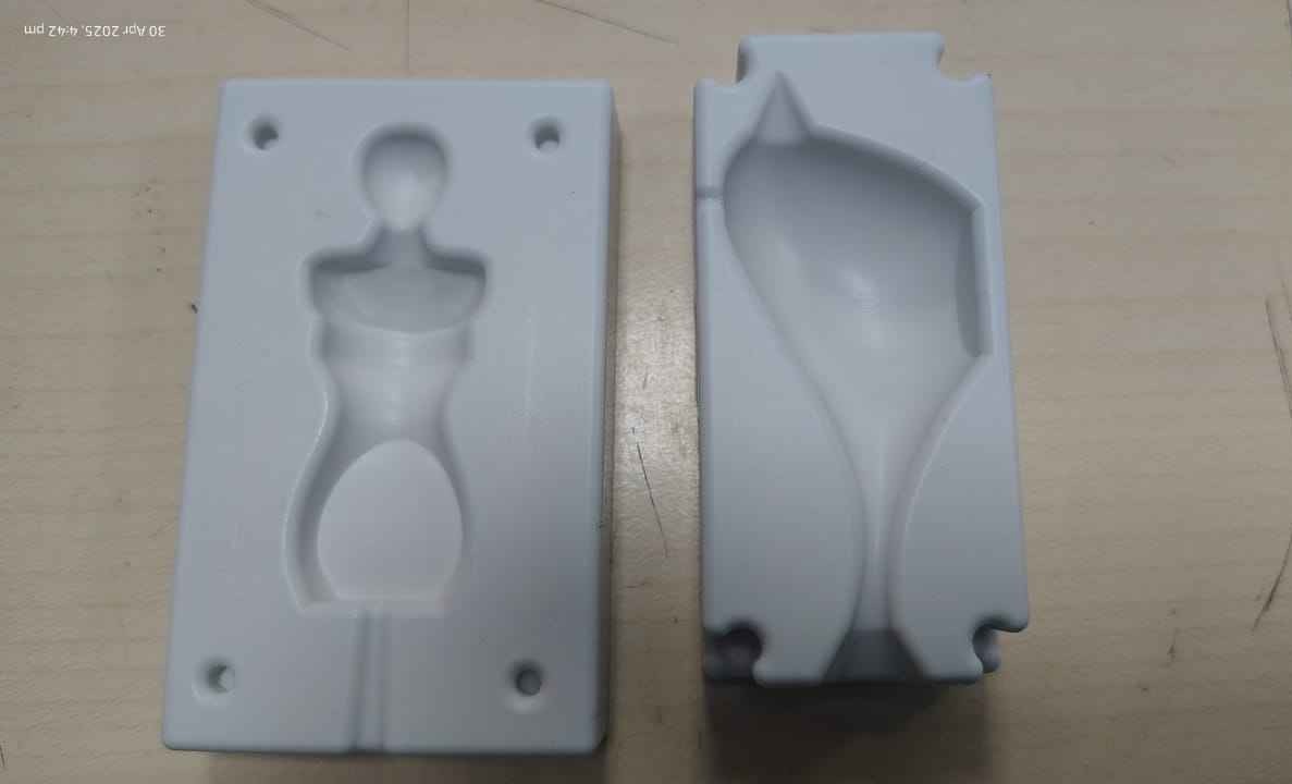
With the mannequin design finalized, I decided to build a mold for it. I created the first half of
the mold using wax milling. Since the design was symmetrical, I planned to use the same mold to pour
silicone twice—once for each side. However, considering the 12-hour curing time for each pour and
the overall time constraints, I decided to create the second half of the silicone mold using 3D
printing to speed up the process.
Before starting the milling process, I merged my file with my friend
Sharvari
Akerkar.
We did so to combined our files to ensure that both our designs would fit in a single wax together and could
be milled in one go.
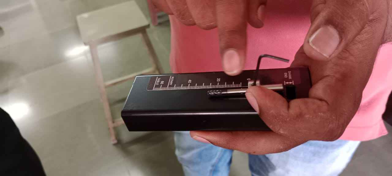
To create the wax mold, I used the MDX milling machine. Know more about the machine
here.
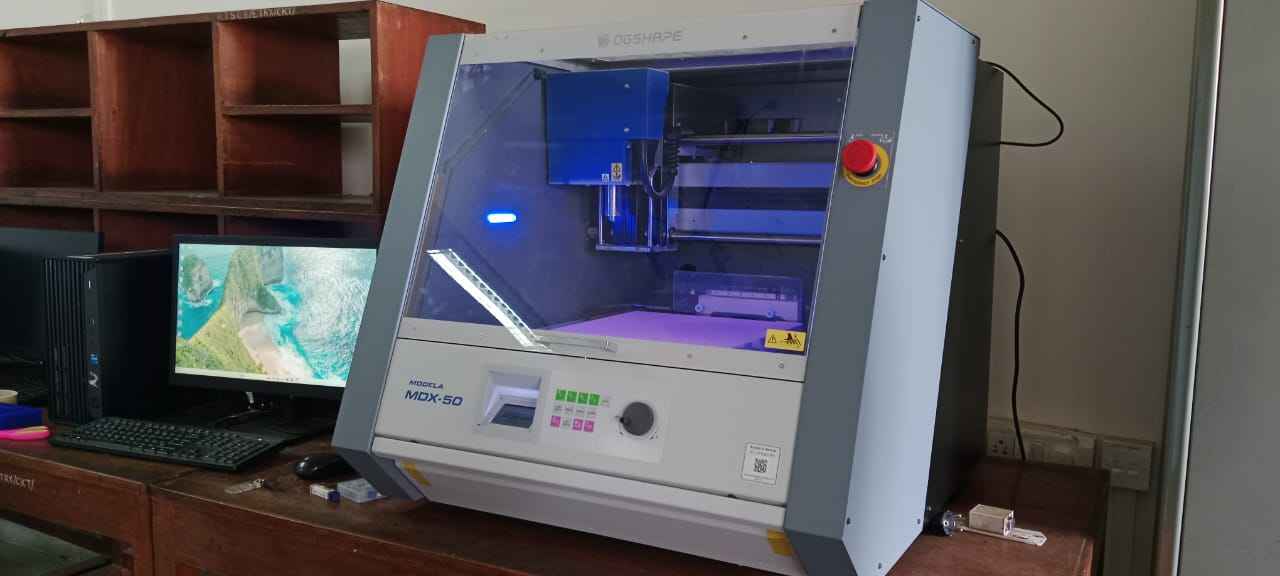
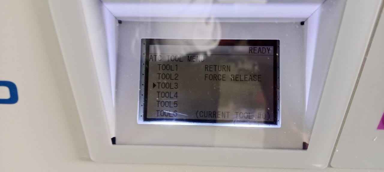
The speciality about this machine is the tool changing feature, we can set the desirable tool at the
required tool section number.
.jpg)
. We can select the tool number at which our required tool is set.
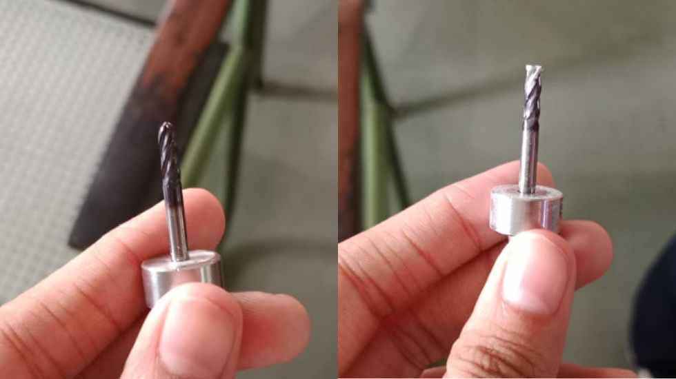
For the milling process, I used two types of milling bits: flat end and ball end bits. The flat-end bit is
ideal for creating straight, flat surfaces. On the other hand, the ball-end bit is perfect for detailed,
rounded surfaces and smaller, curved areas, allowing the machine to create finer features, such as the
bird's curves and intricate details.
I used a measuring tool to ensure the milling bit was positioned correctly. This tool helps set the bit's
height relative to the wax block, ensuring that the cuts are accurate and that the bit doesn’t cut too
deeply into the material.
After that place the wax block properly on the bed of the machine.
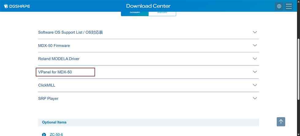
V Panel software for the Roland MDX-40
I visited the official Roland DG and searched for the software. Click on the highlighted box to download it
at
Download V-pan for MDX-40.
Next,We download SRP Player, the software is used to convert 3D models into milling instructions for the
Roland MDX-40.
It prepares your design by generating toolpaths based on the geometry of the model and the chosen milling
bits. Download link for SRP
Player
Once you have downloaded the software load your 3d model. Next go Option > Add/Remove Tool
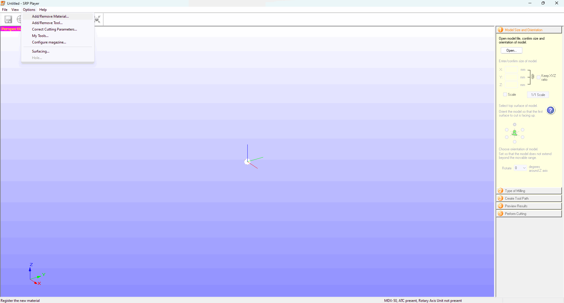
For this project, I added a 3.0mm square tool and a 6mm end mill.
.png)
Tool Specifications, can be modified as per requirements of the diameter/ length.
.png)
Thus, tool number 3 and 5 were the tools I used.
.png)
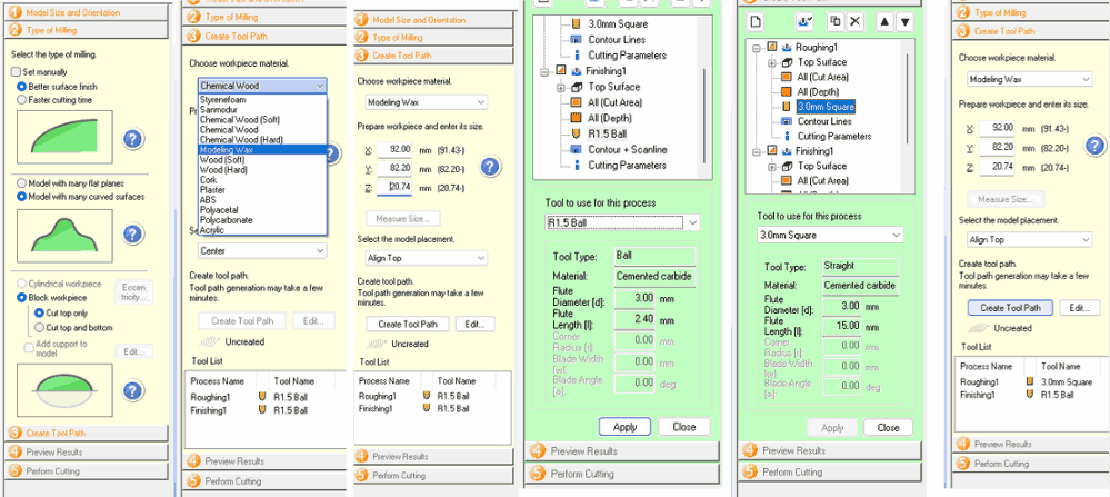
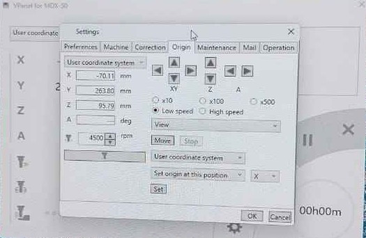
For the settings go with the step by step process for which you can refer to the image below.
Model Size and Orientation
Type of Milling:
Select the type of milling.
Create Tool Path-
Choose workpiece material: Modeling Wax.
Prepare workpiece and enter its size: X: 92.00 mm,
Y: 82.00 mm,
Z: 20.74 mm.
Select the model placement:
Align Top
Create tool path:
Click Create Tool Path
Tool Configuration for Roughing: 3.0mm Square.
Tool Type: Straight.
Material: Cemented carbide.
Flute Diameter [d]: 3.00 mm.
Flute Length [l]: 15.00 mm.
Tool Configuration for Finishing: R1.5 Ball
Tool Type: Ball
Material: Cemented carbide
Flute Diameter [d]: 3.00 mm
Flute Length [l]: 2.40 mm
Preview Results
Accessible after toolpath creation.
Perform Cutting
Final step after previewing the toolpaths.
With everything set up your milling is started.
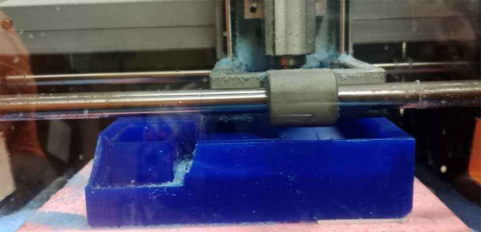
Milling done
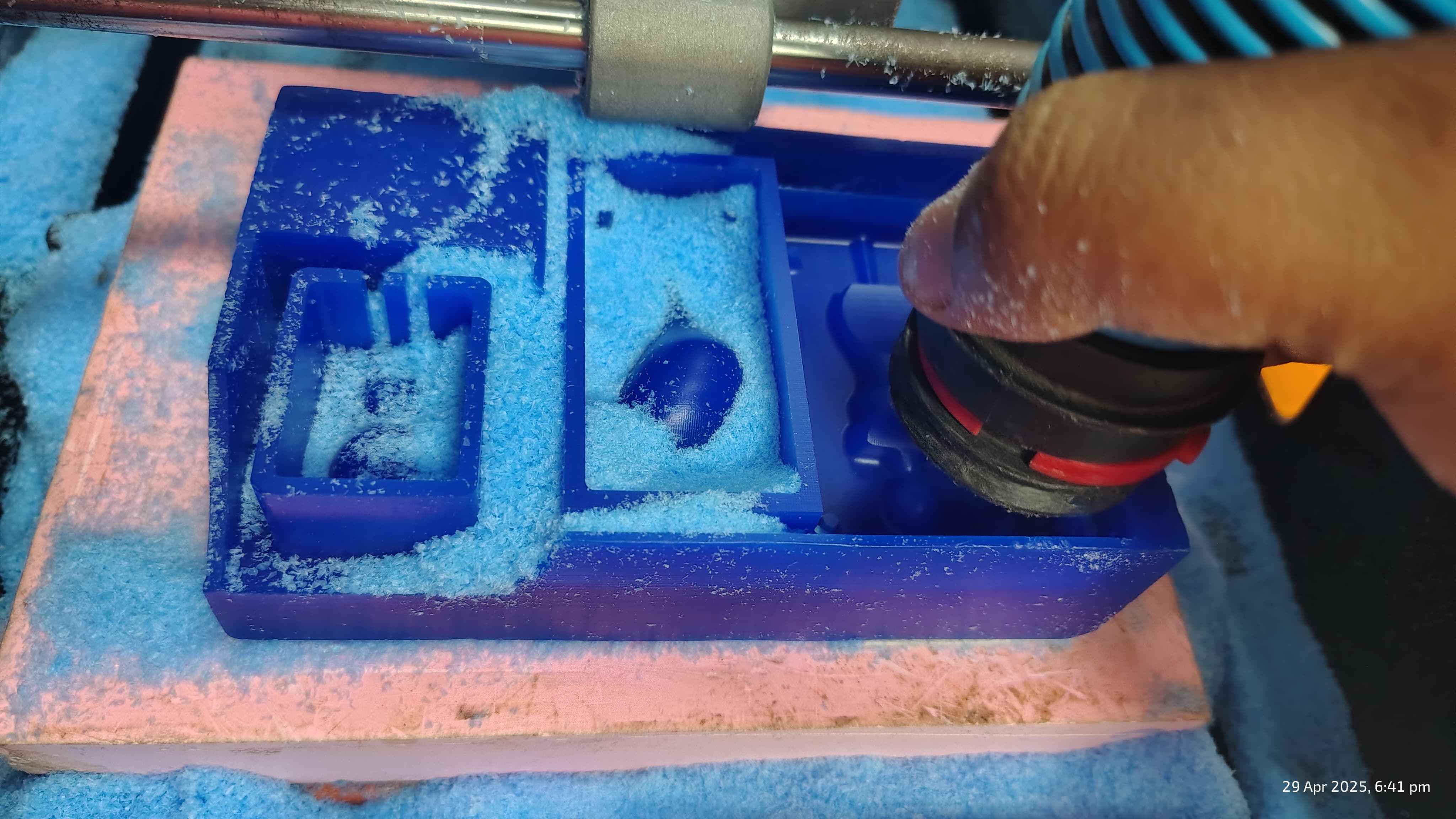
After the milling was completed, I carefully vacuumed the wax mold to remove any leftover material and
debris.
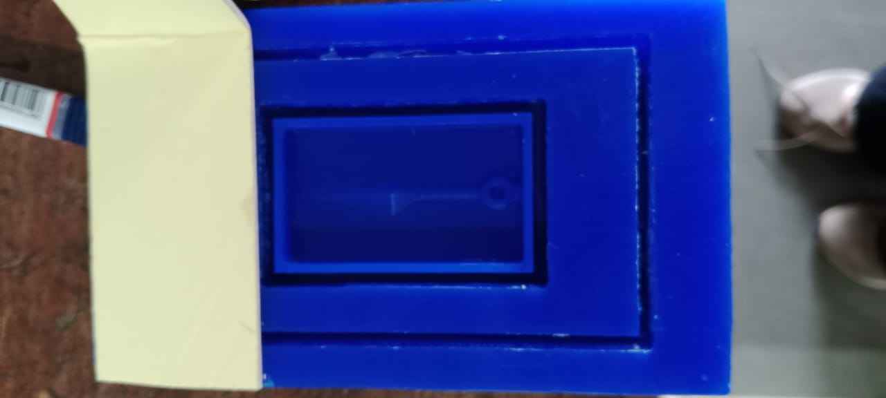
Final Wax Mould
3D printing
Bamboo Labs: Link to slicing software for the Bamboo 3D printer, Bamboo Studio
Initial model loaded onto the Bambu Studio slicer with base settings applied.
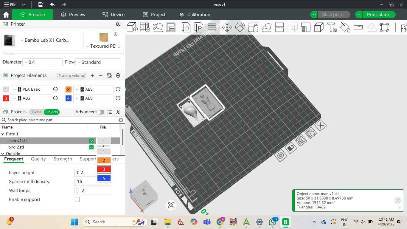
I adjusted the layer height to 0.1mm for a smoother layer finish of the mould.
Initial model loaded onto the Bambu Studio slicer with base settings applied.
Final Mould
I gently sanded the surface using fine-grit sandpaper as there were minute imperfections in the
model.
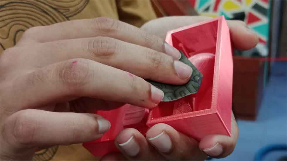
Final Moulds
Mother/ Negative mould
Safety Precautions:
Before starting, I made sure to follow safety guidelines:
I wore gloves to protect my skin from any chemical reaction or irritation.
I worked in a well-ventilated area so that I wouldn’t inhale any fumes.
I also wore a mask and safety glasses to protect myself from accidental splashes.
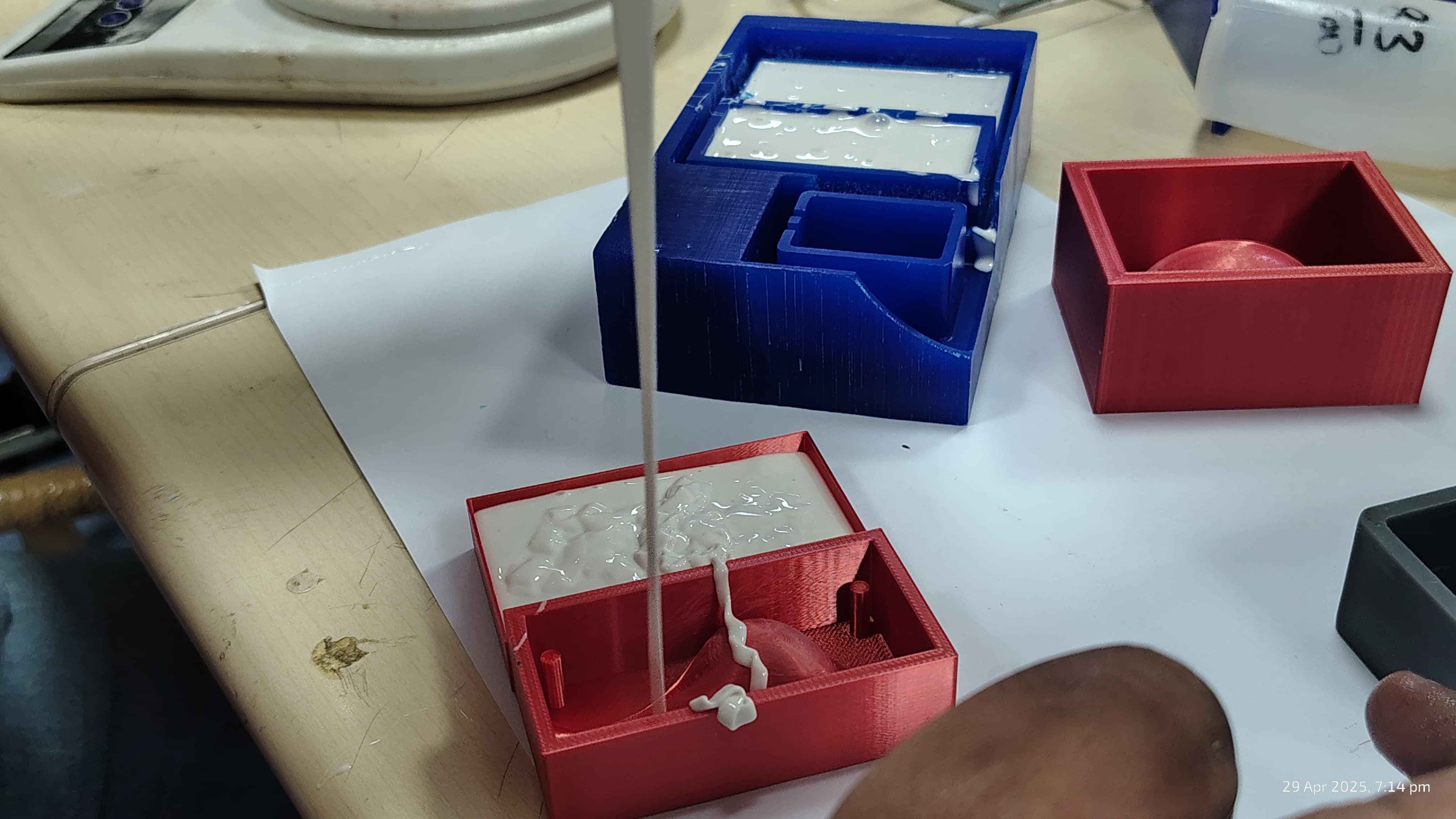
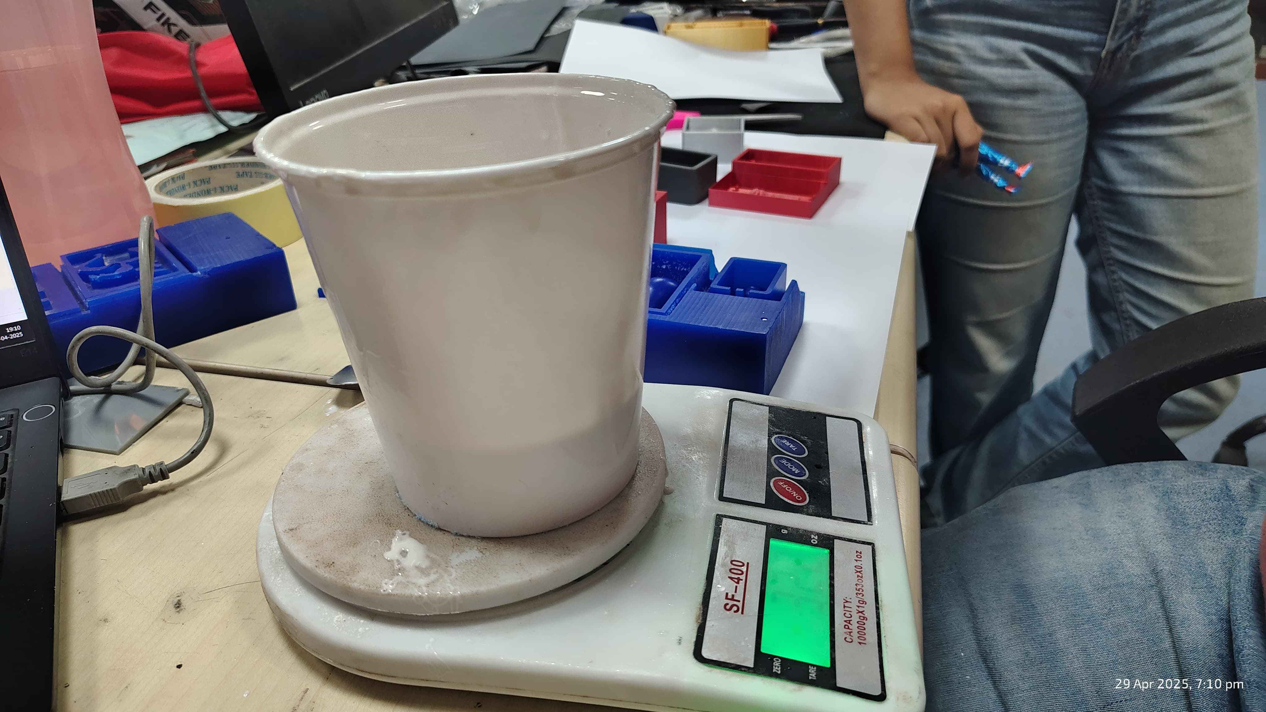
Using a digital scale, I carefully weighed out Part A and Part B in the correct 1:10 ratio.

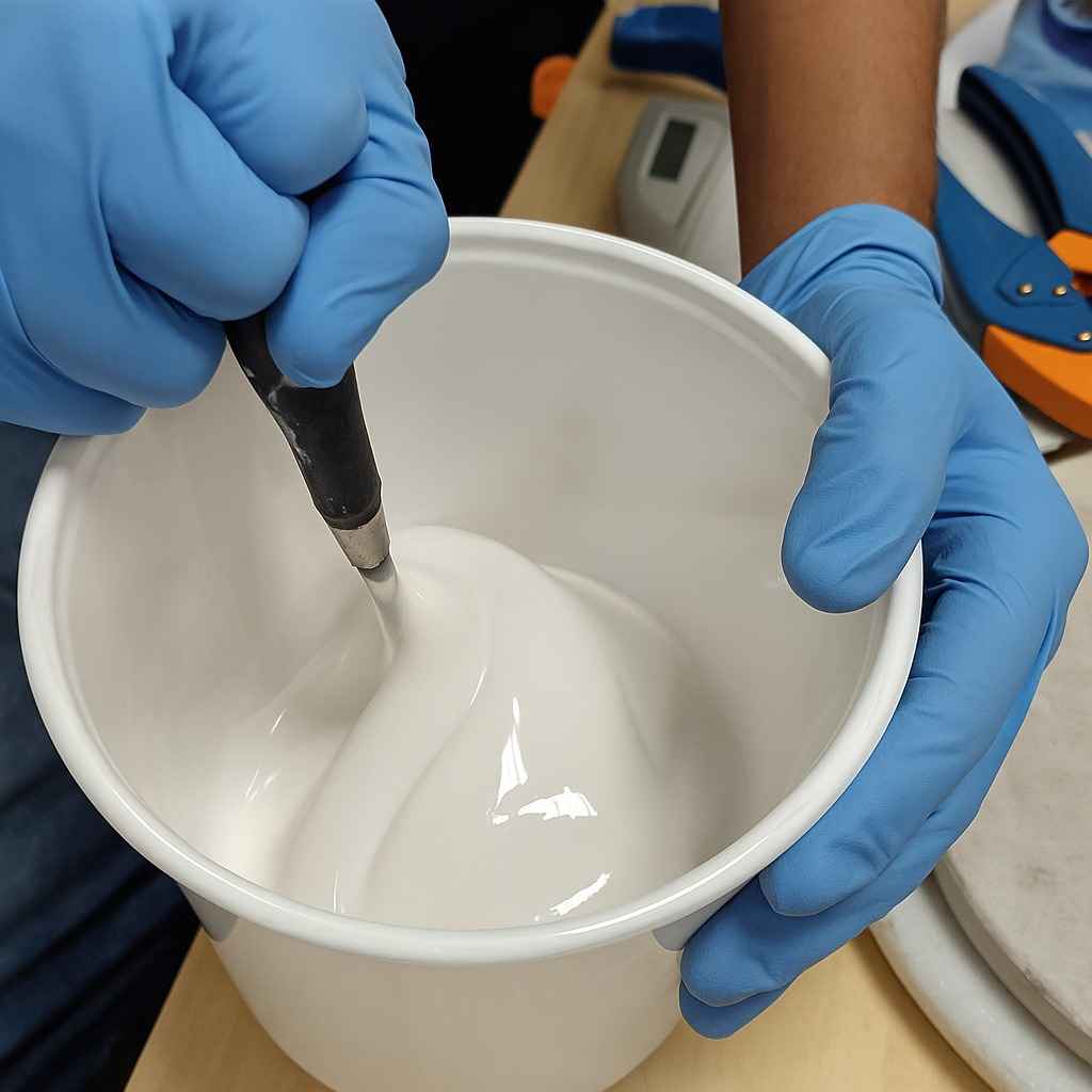
I poured both into a clean mixing cup and mixed it slowly and thoroughly.
Note: It's important to scrape the sides and bottom plus to mix it in circular patterns only and not whisking
like,
to ensure the two parts combine fully—this
prevents soft or uncured spots in the final mold.
Stiring until silicone it gets uniform consistency
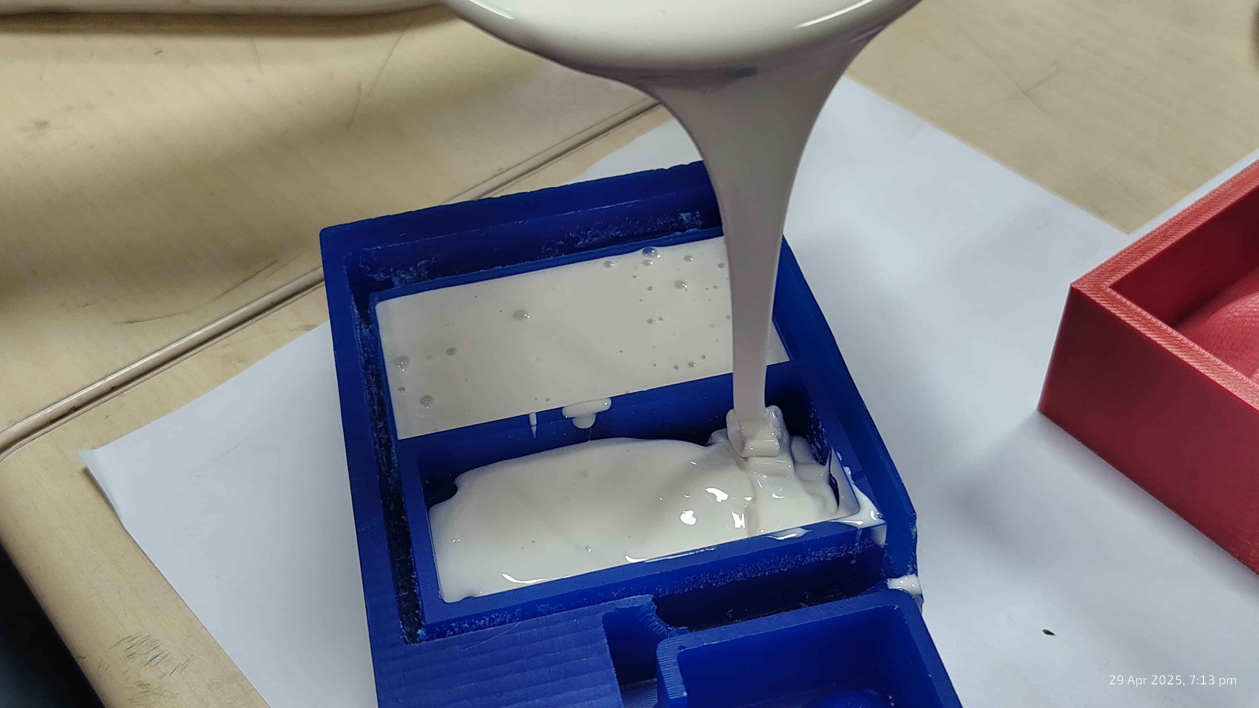
I starting pouring from one corner and letting it naturally flow. This helps avoid trapping air
bubbles.
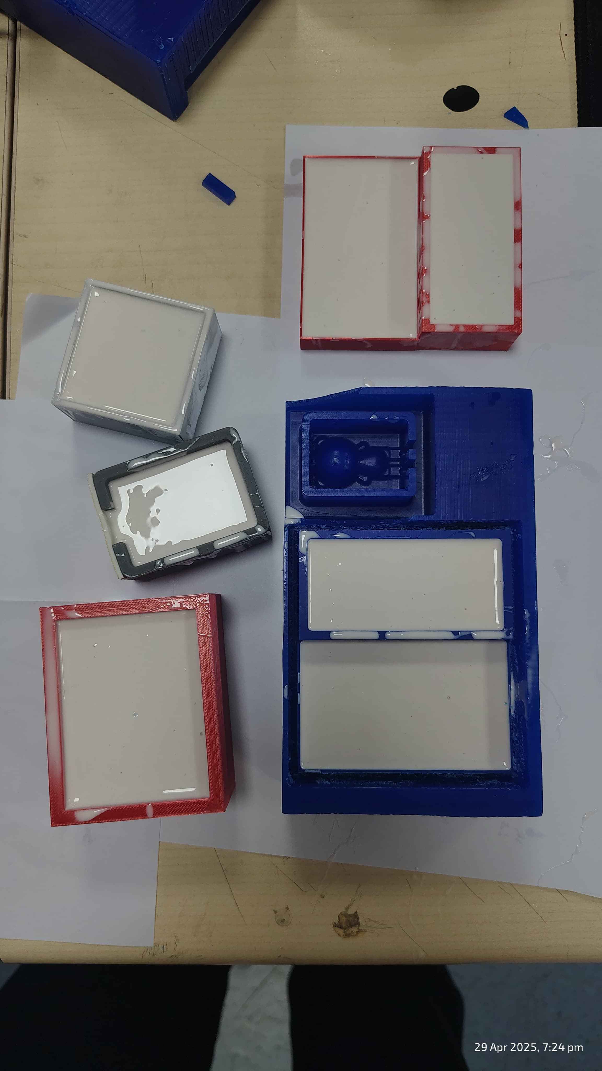
9hrs later!!!!!! I carefully removed the wax or 3D printed model, leaving behind a clean, flexible
negative mold ready for casting the final material.
Removing mother moukd from the master mould.
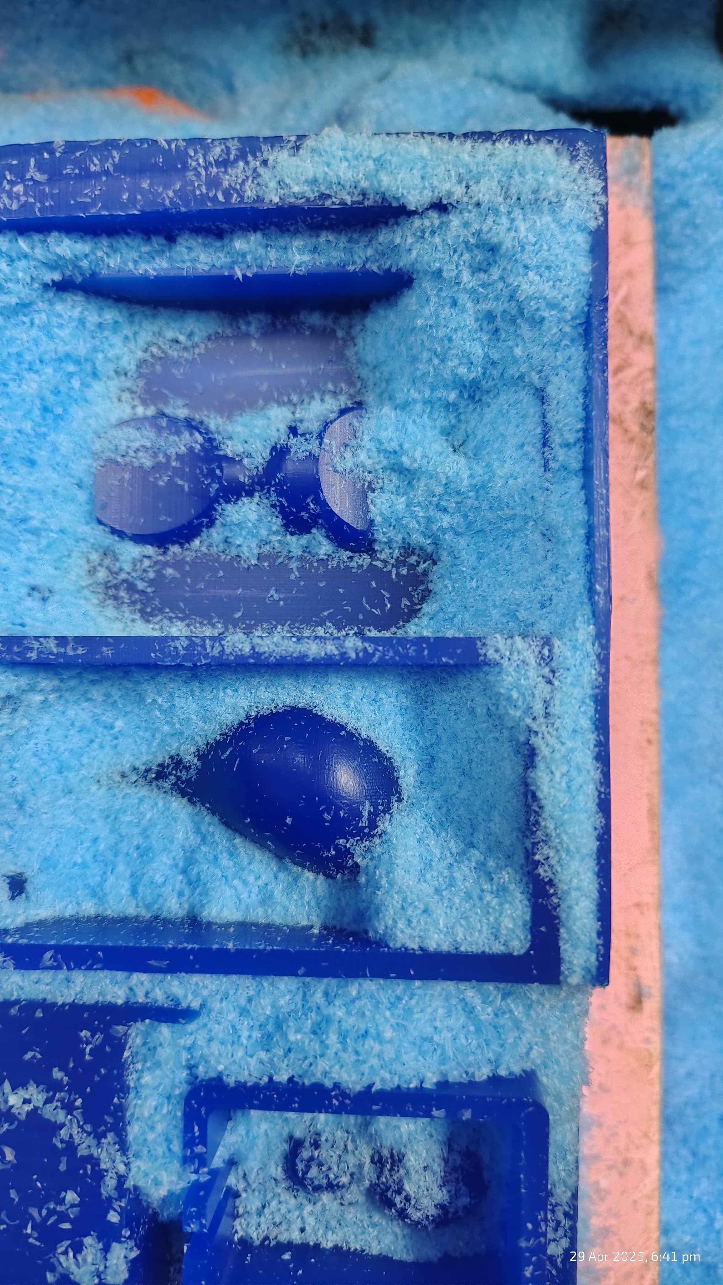
Checking 3d printed egg shell material smootheness.
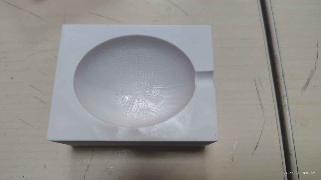
The finish was quite smooth, adding water and cooling it to see the cast quality in form of ice.
.jpg)
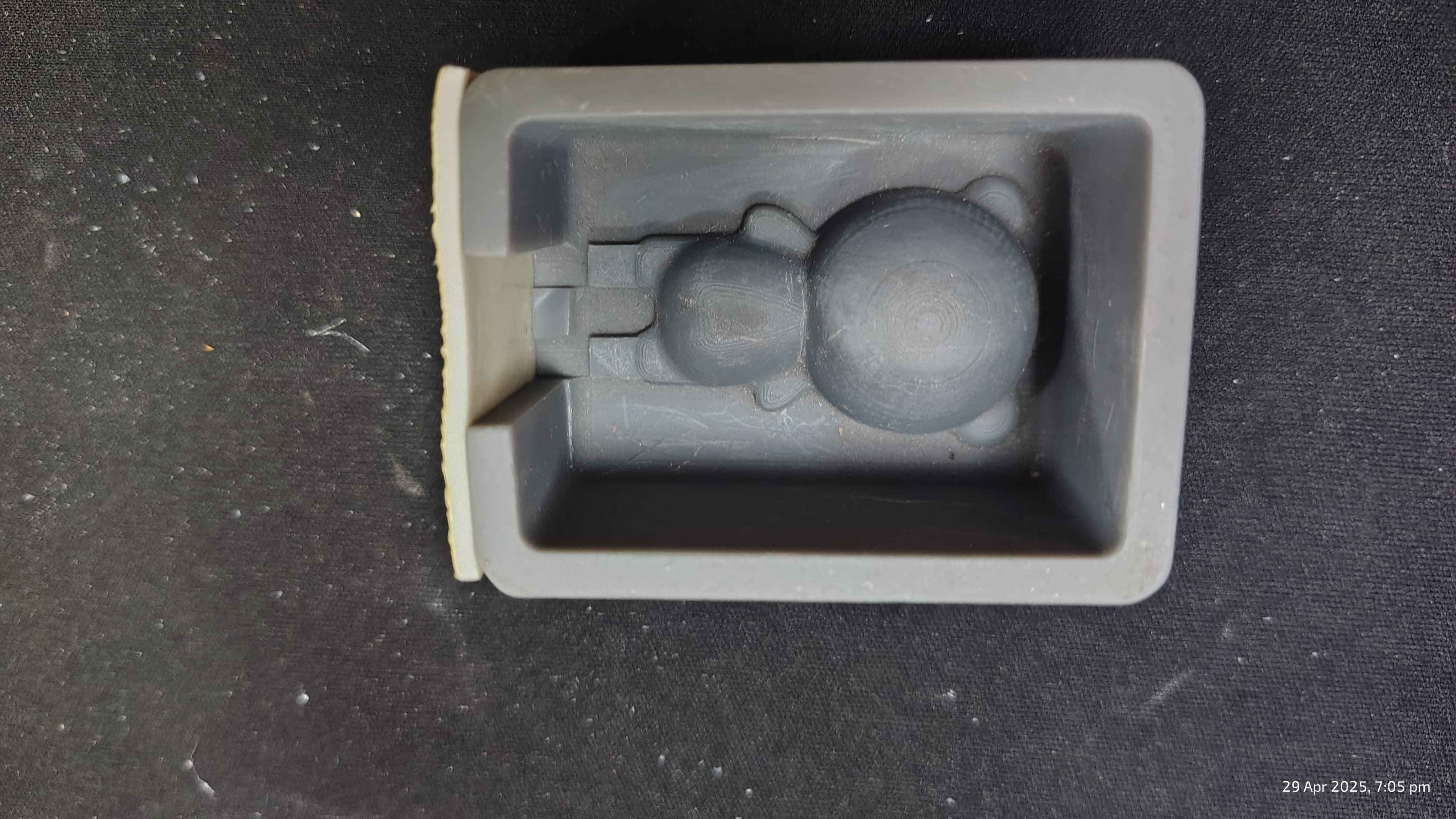
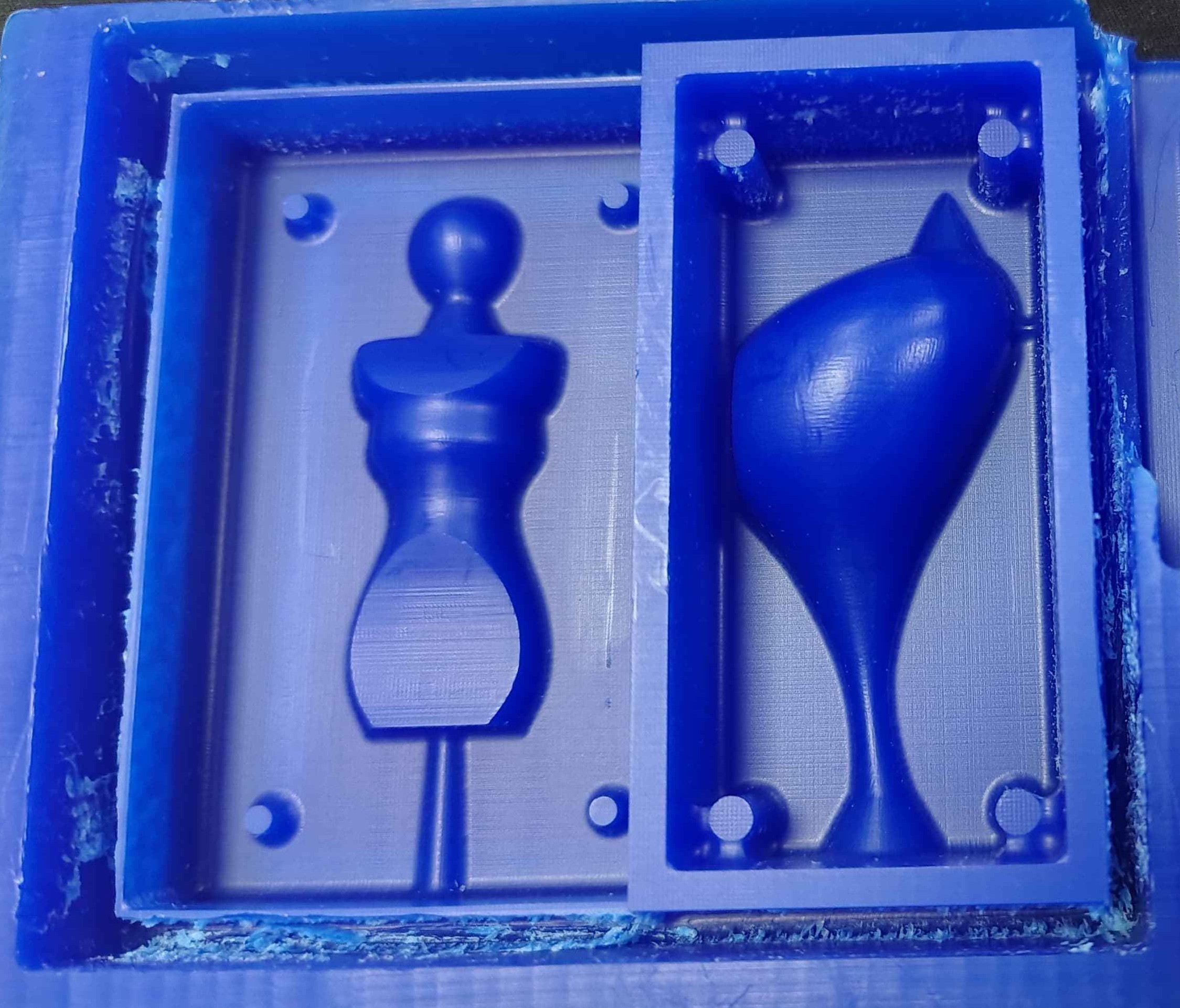
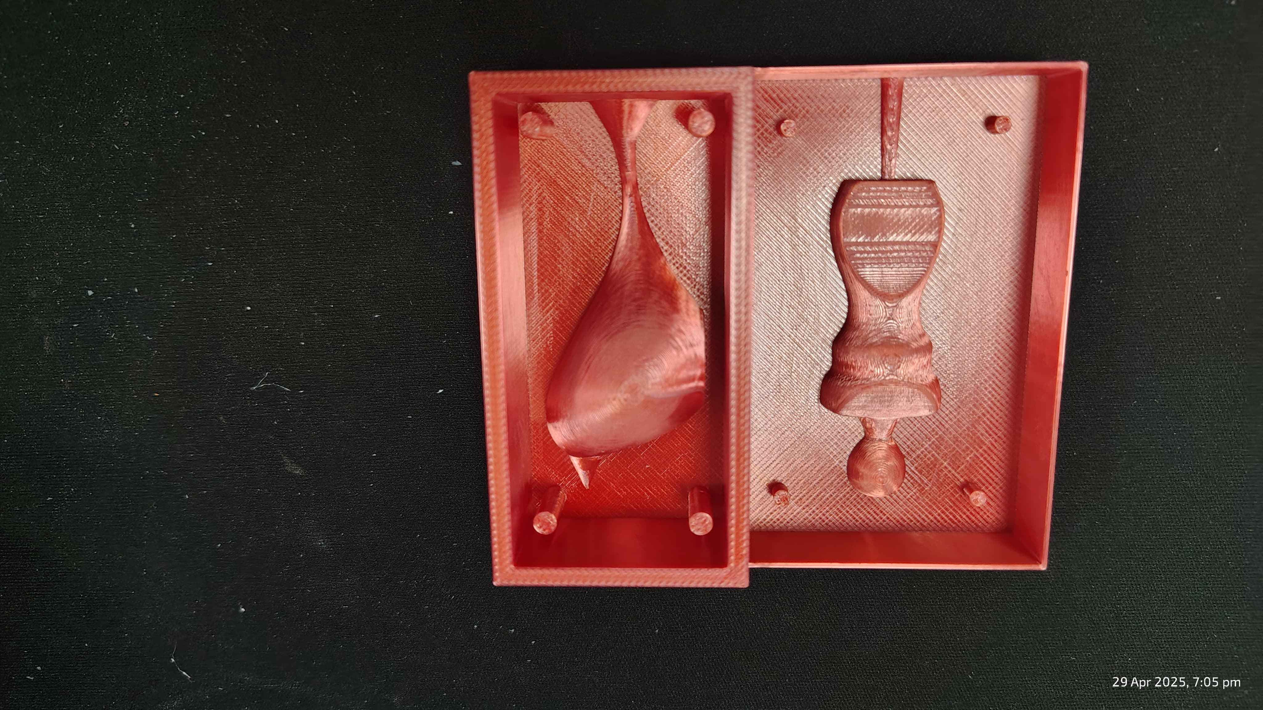
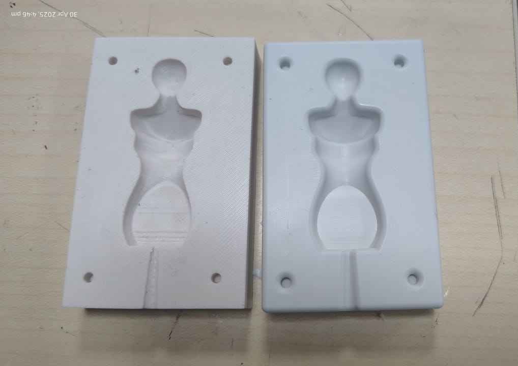
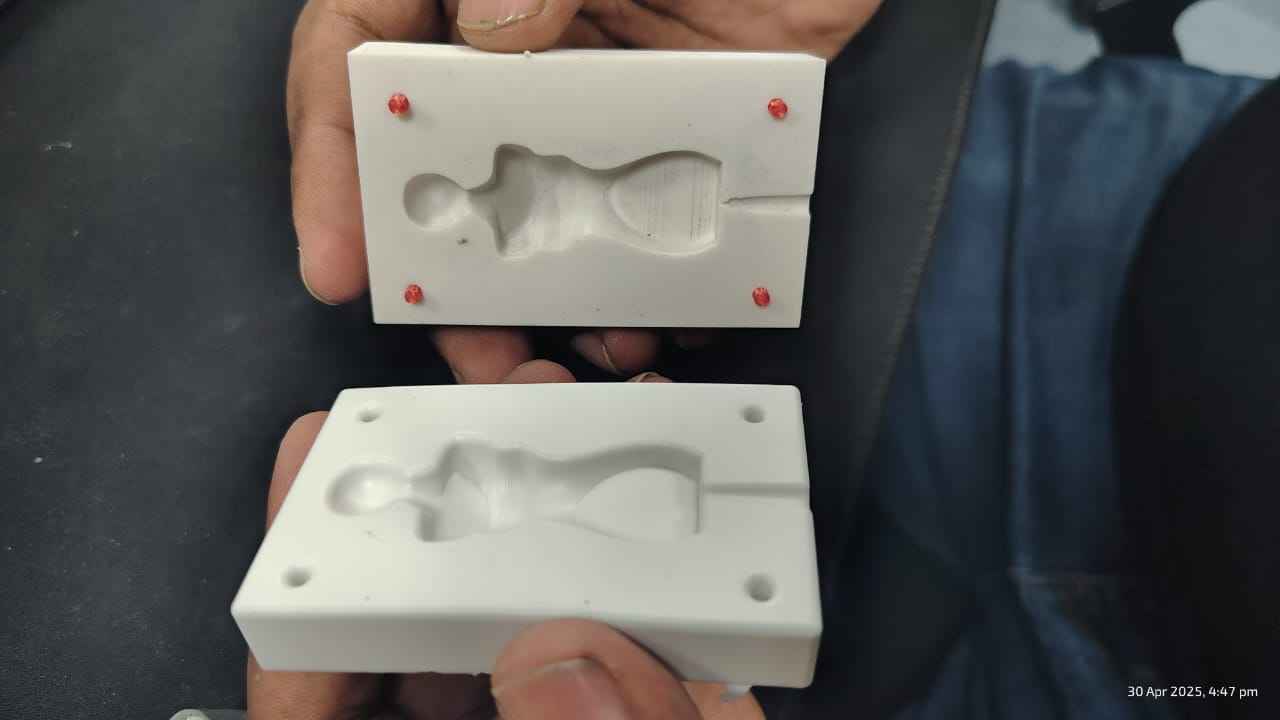
Manequinne moulds, comparing 3d printed and wax milled mother moulds, Wax milling gave a smoother
finish. The comparison is given in the table below.
The mould along side is Sharvari's birdy mould. The holes she made for binding two moulds gave an
error which was a learning for me,
Check out her
documentation. to learn about her process.
Comparing Test casts
| Feature |
3D Printed Mold (Left in Image) |
Wax Milled Mold (Right in Image) |
| Surface Quality |
Slight texture due to visible layer lines |
Very smooth surface finish from milling |
| Detail Accuracy |
Moderate – shows print lines; curved details are less defined |
High – smooth and precise curves from subtractive milling |
| Effort Before Pouring |
Requires post-processing like sanding before silicone pouring |
Minimal – ready to use directly after milling |
| Appearance |
Shows printing artifacts like steps or ridges |
Clean, polished, and professional appearance |
| Ideal Use Case |
Quick prototyping or low-fidelity casting |
Fine finish casting and high-fidelity mold production |
| Time Factor |
Faster to produce – minimal supervision needed |
Slower – milling takes more time and setup |
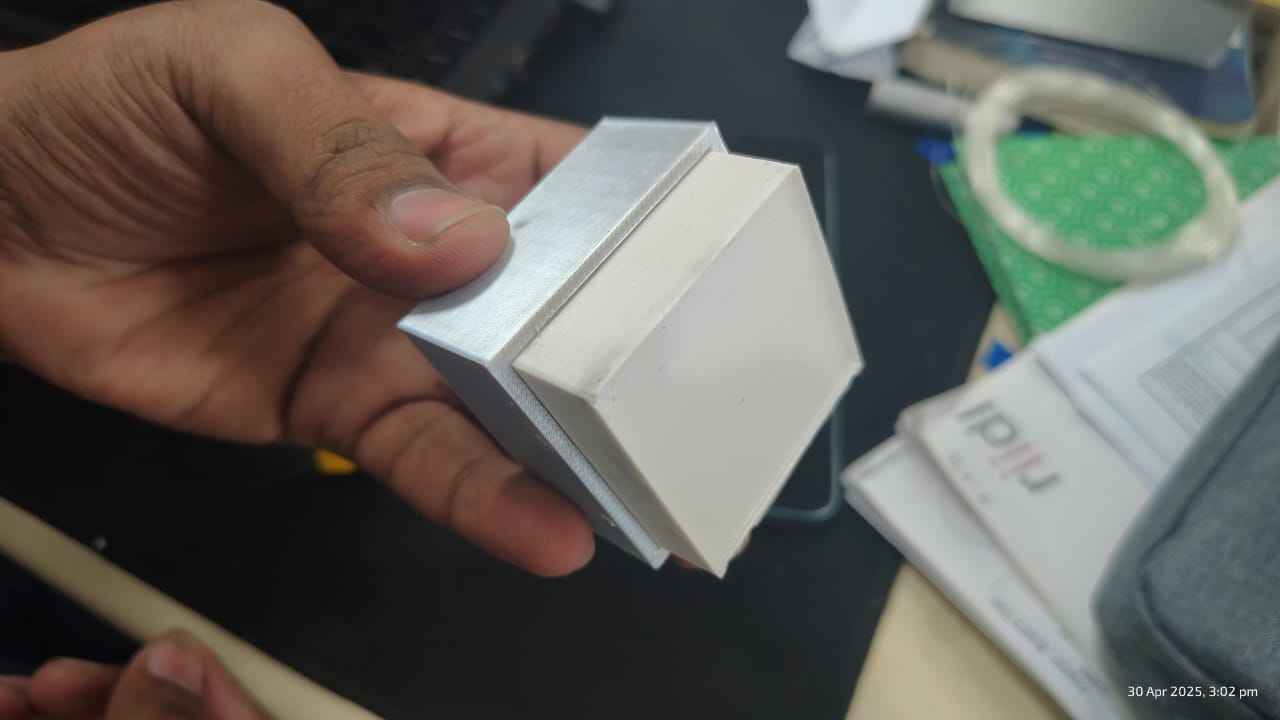
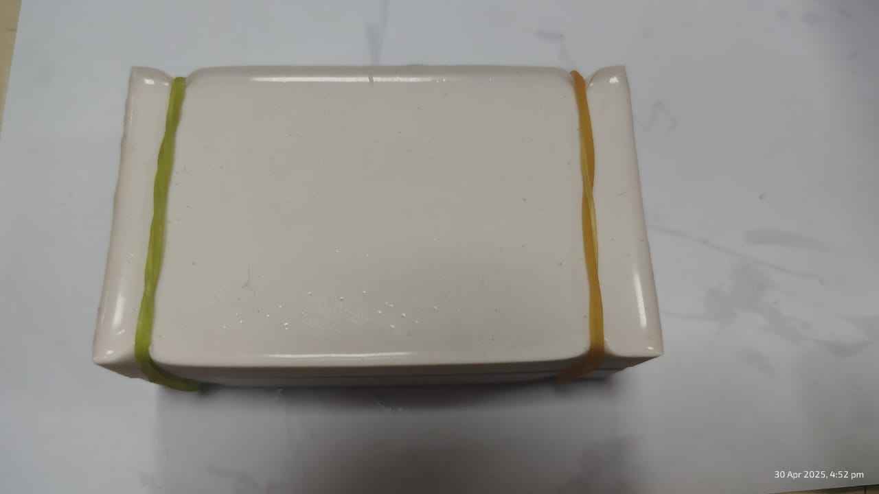
Final mould, created 3d printed inserts for binding the two parts.
Added the inserts and joining of the parts together.
Once binded, added a rubber at the egdes of the mould.
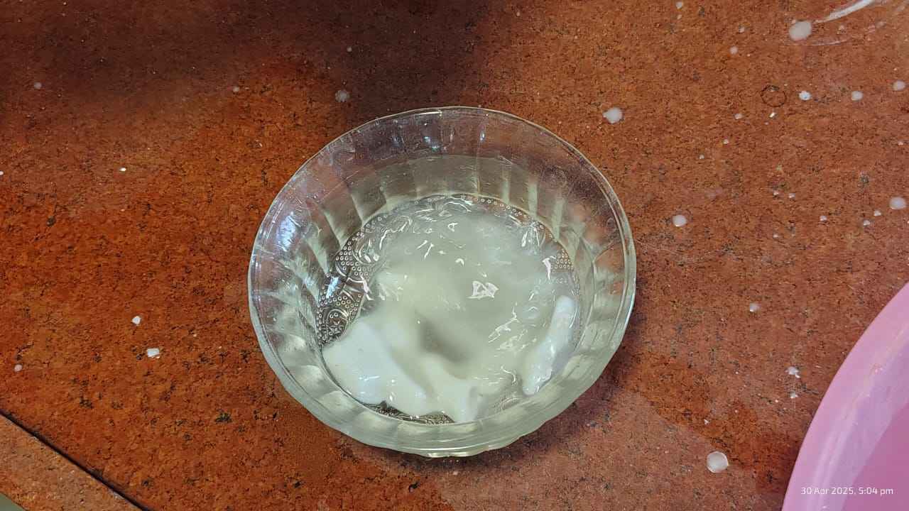
I planned on making a wax mould for which I used candles.
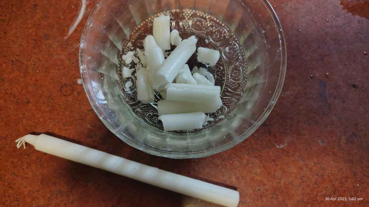
Melted the candles
The pouring hole which I created was a perfect match for a syringe inserting.
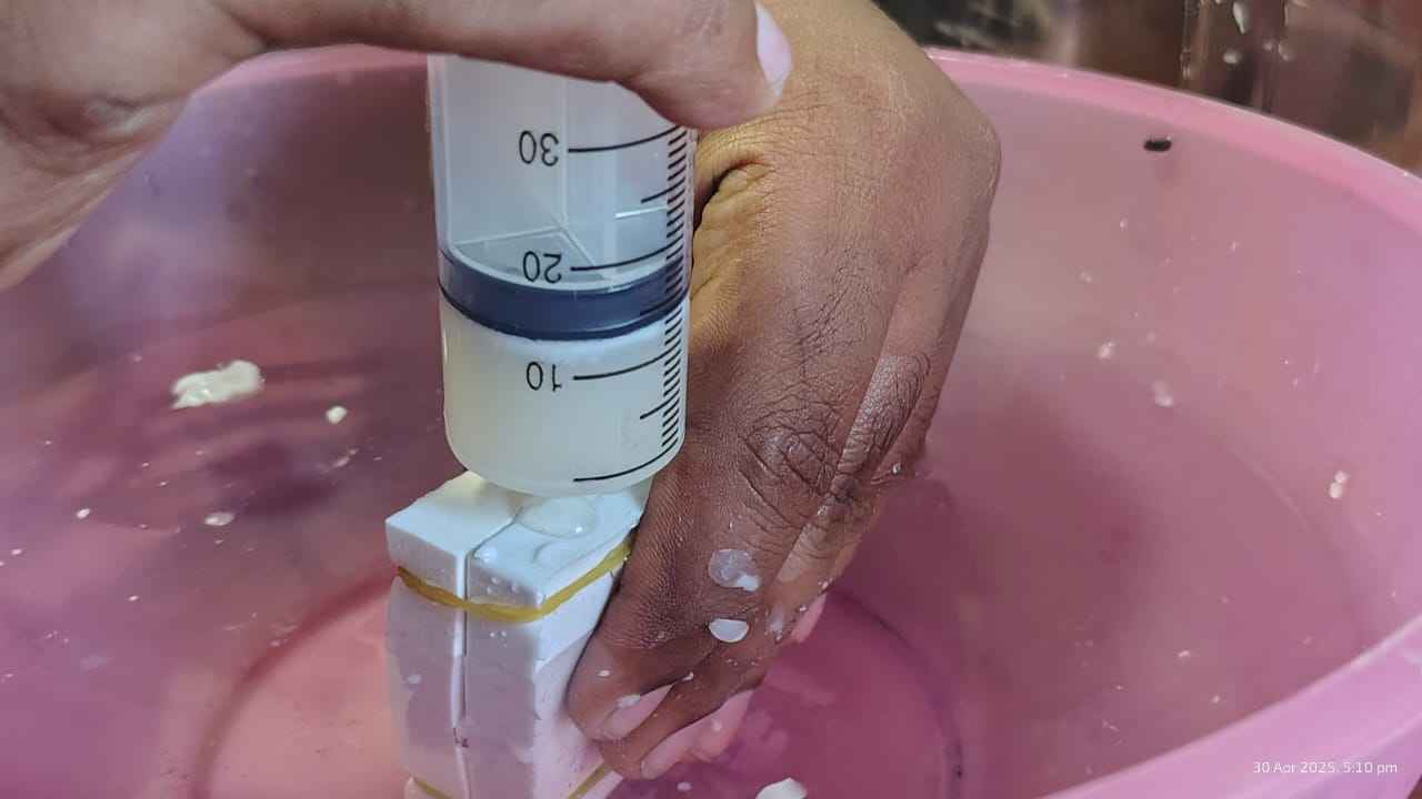
Note: The size of the pouring hole should always be considered as per the type of cast used.Thus, for a
thicker cast the
diamter of the hole should be bigger.
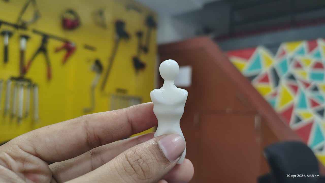
Final Cast
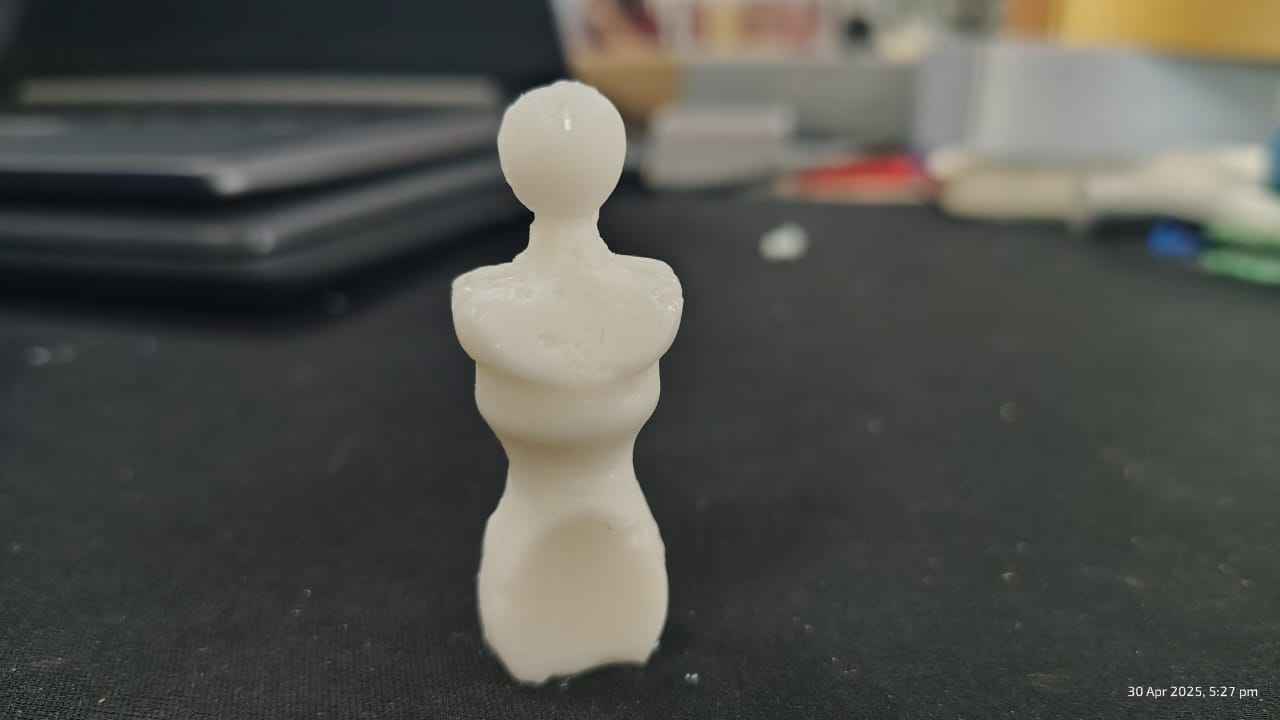
Difference in the 3d printed and wax milled silicon cast.
.jpg)
Although the 3D printed cast showed clear surface imperfections—such as visible layer lines, slight warping, or
uneven finishes—the wax casts derived from both moulds surprisingly did not exhibit significant differences in
terms of these flaws. This could be due to the way wax fills the mould more smoothly, allowing it to self-level
and soften out irregularities. As a result, even though the original 3D print had notable defects, the casting
process minimized their visual impact, producing a relatively uniform surface finish across both wax outcomes.
This highlights how material properties and casting techniques can influence the visibility of imperfections in
the final form.
Group Assignment
In group work we were supposed to review the safety data sheets for each of your molding and casting
materials, then make and compare test casts with each of them compare printing vs machining molds.
Product Overview:
SILASTIC™ RTV-3483 Mold-Making Base and RTV-3083 Curing Agent are
ideal for detailed reproduction of art objects, figures, and similar items.
Datasheet PDF: SILASTIC™ RTV-3483 Mold-Making Base.
They offer:
- Excellent release properties
- High flowability and elasticity
- Long working time
- Low hardness
- High tear resistance
Suitable for use with plaster, polyurethane, and polyester resins.
Handling & Usage Guidelines
- Clean surfaces thoroughly; apply release agent on porous materials.
- Mix base and curing agent in a 100:5 ratio.
- Stir well, keeping temperature below 35°C (95°F).
- De-air to remove bubbles and pour immediately after mixing.
- Initial cure in 24 hours; full cure in 7 days.
Safety & Storage
- Consult Safety Data Sheet (SDS) before handling.
- Store in unopened containers below 32°C (89.6°F).
- Dispose according to local regulations. Handle empty containers with care.
Warnings
- Not suitable for food, dental, or skin contact molds.
- Degradation may occur above 150°C (302°F) or during long use with
aggressive resins.
- Inspect molds periodically in long production runs.
Key Features
- High flowability, long working time (90–120 mins)
- Low hardness (13 Shore A), high elasticity (680%)
- Strong tear resistance (25 kN/m), excellent release
- Thixotropic option for vertical surfaces
Usage
- Mix ratio: 100 (base) : 5 (curing agent)
- Stir well, de-air, pour immediately
- Cures in 24 hrs; full strength in 7 days
- Compatible with plaster, PU, and polyester resins
Hero Shot
Project files
Manequinne File design
Egg mould file design .png)
.png)
.png)