Assignment Brief:
- Design a machine that includes mechanism+actuation+automation+application
- Build the mechanical parts and operate it manually
- Document the group project and your individual contribution
This week's documentation is posted on on my Fabmate Devanshi's page.We played chits to divide and manage the work and the part which came by my way was Design. The concrete bit I handles here was DFA and alsa made my contributions in mechanism and major part of actuation.
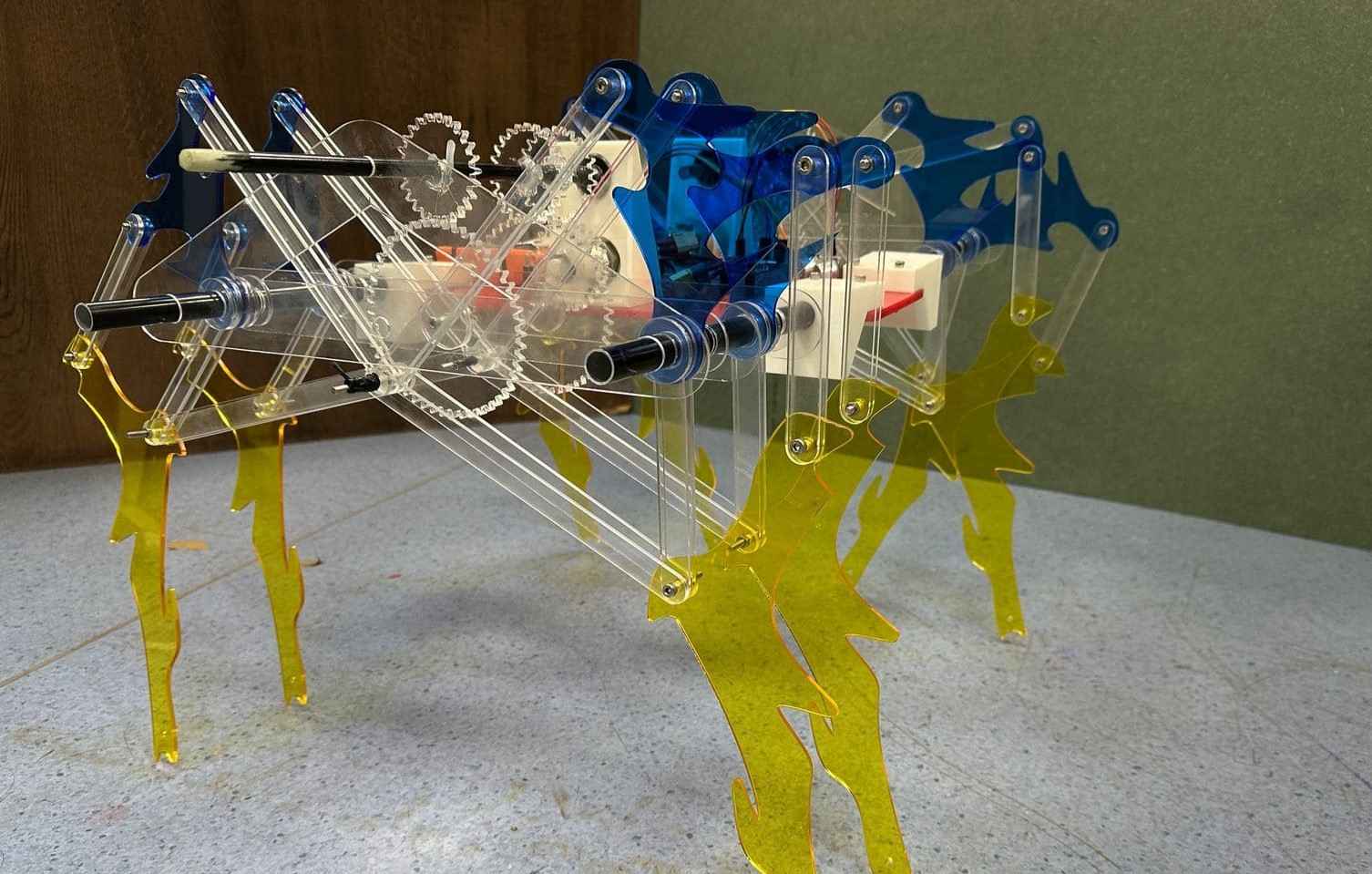
Final Product
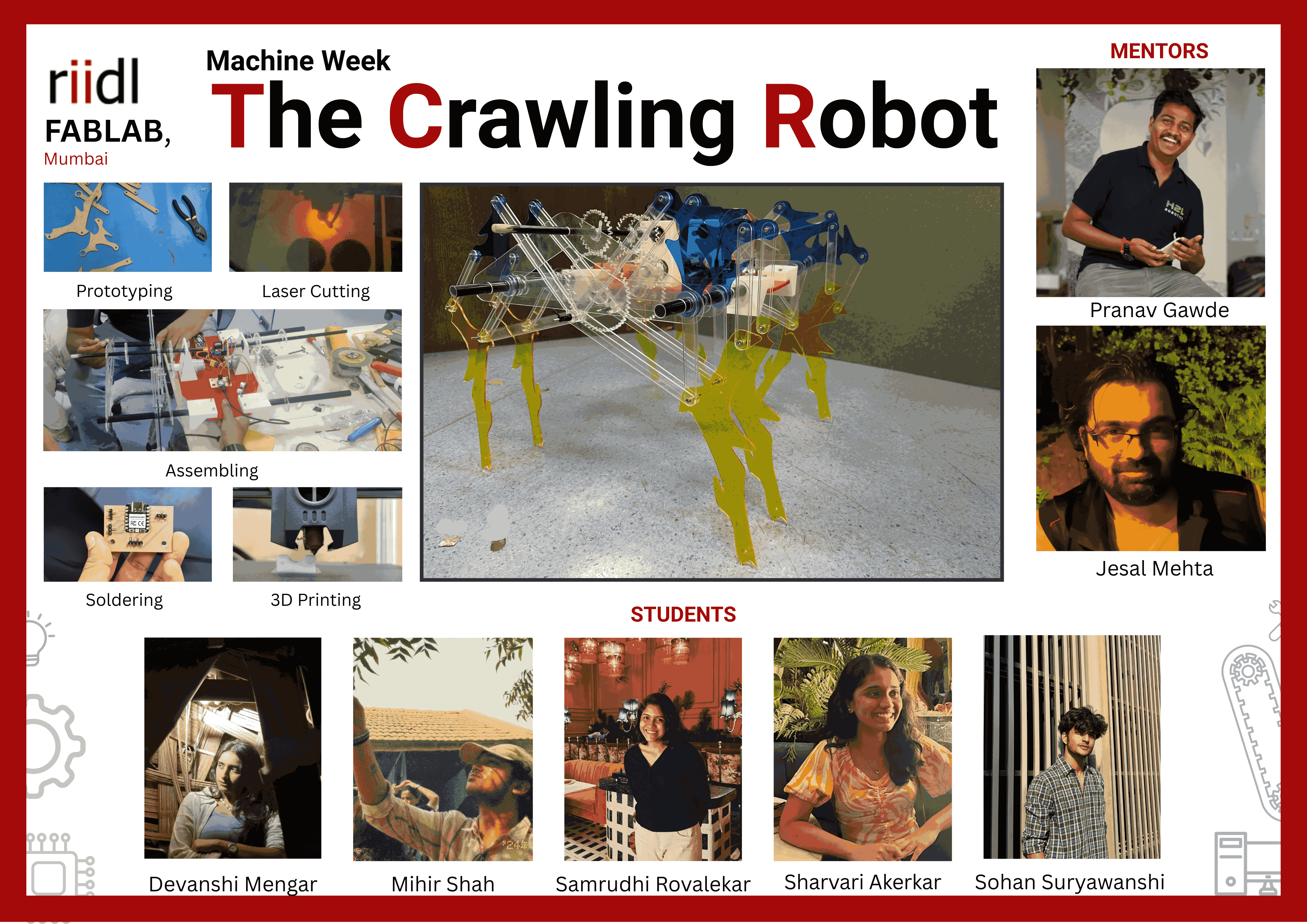
Final Poster
Find the detailed documentation my fab mate: Devanshi's page.
Final Product Video
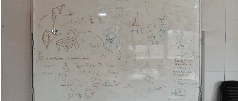
Ideation: Her we did the Project planning, of form material, material cost, design, design to mechinism, actuation etc.
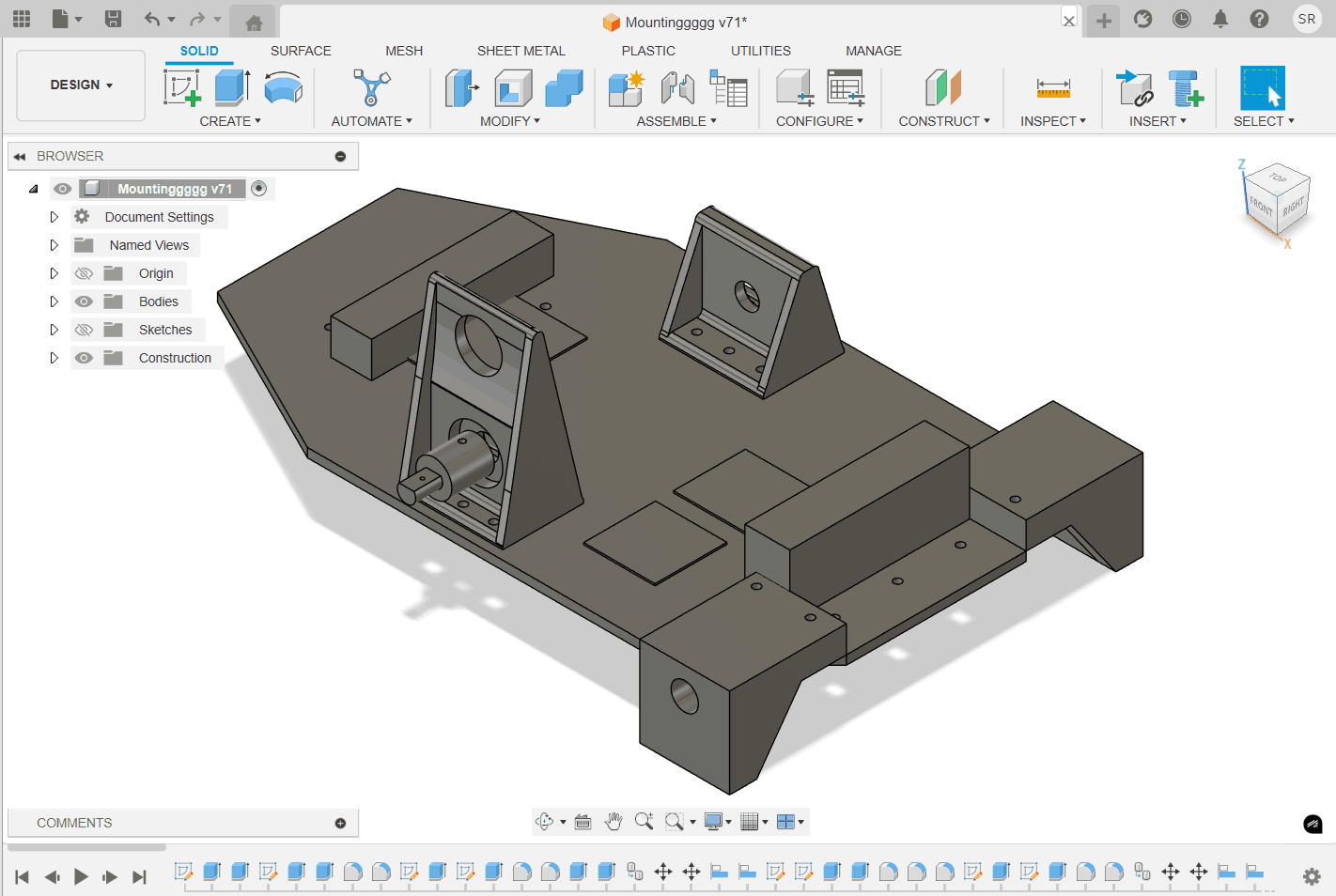
Design Process
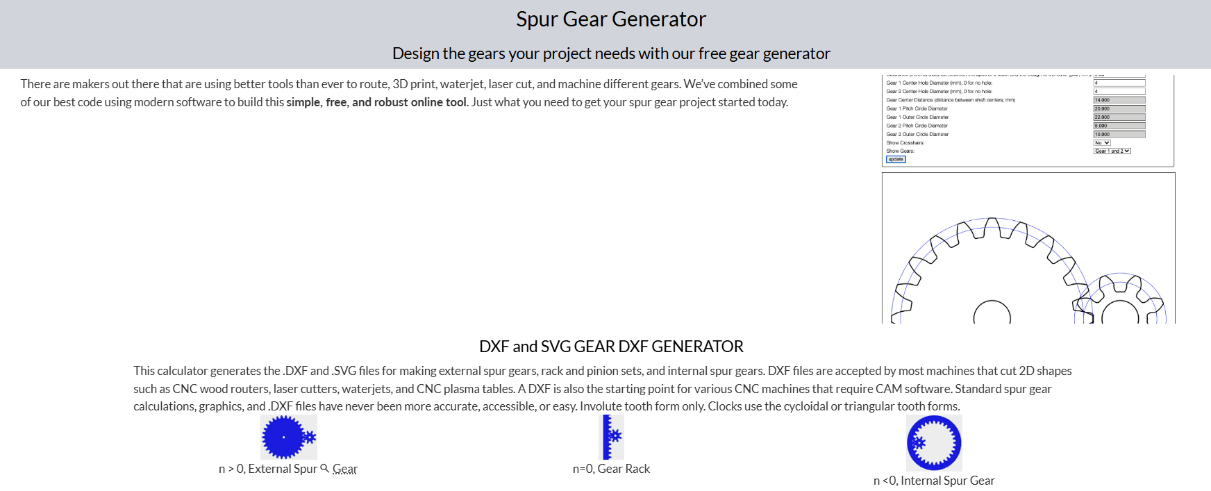
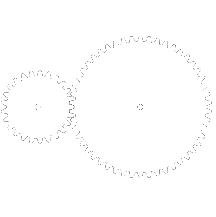
Design Process: We began by individually modeling each part, starting with basic sketches and then extruding them into 3D forms. Key features such as holes for fasteners and alignment slots were incorporated to ensure easy assembly and structural stability. We maintained clean and simple geometries throughout the design to facilitate straightforward manufacturing and assembly. To design gears for power transmission, We used an online spur gear generator application. In the app, we created a gear pair with 50 and 100 teeth, aiming for a 2:1 transmission ratio. This setup allows the smaller gear (50 teeth) to drive the larger gear (100 teeth), effectively reducing speed and increasing torque for better power transmission. Key parameters selected: Gear Type: Spur Gear (External Mesh) Module: Standard (based on application needs) Pressure Angle: 20° (commonly used for smooth engagement and strength) Center Distance: Automatically adjusted according to teeth and module Tooth Profile: Standard involute shape
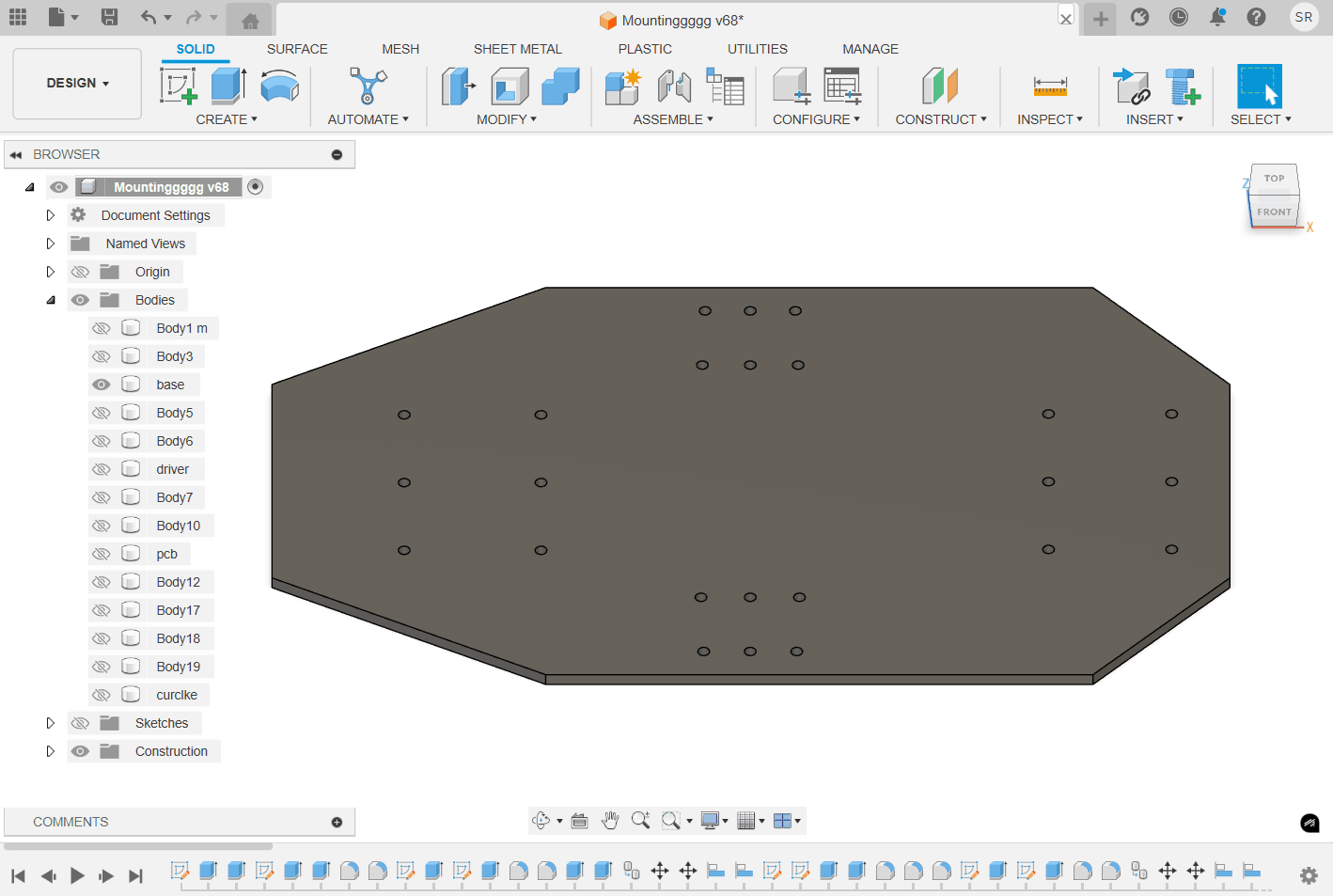
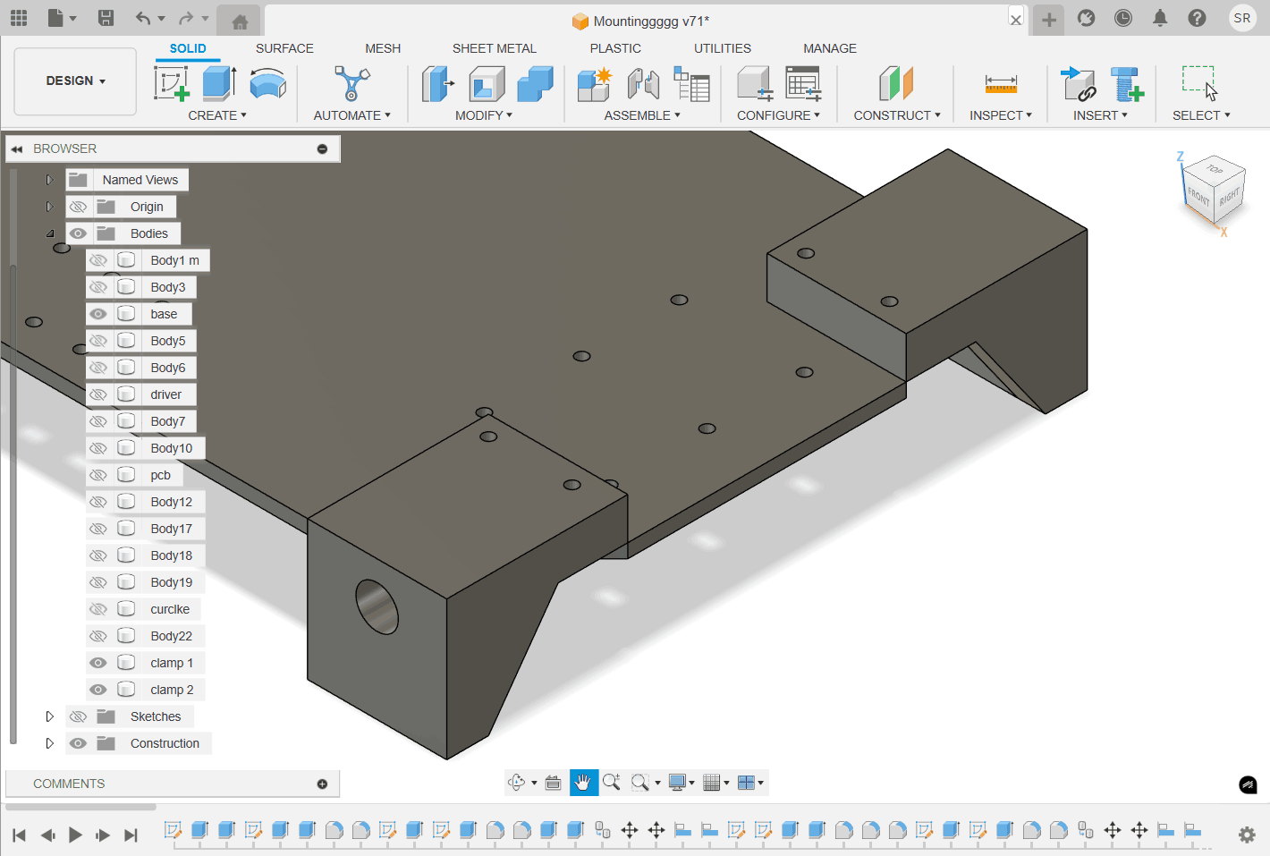
Calculated and designed holes for mounting
Designed mountings for the motors
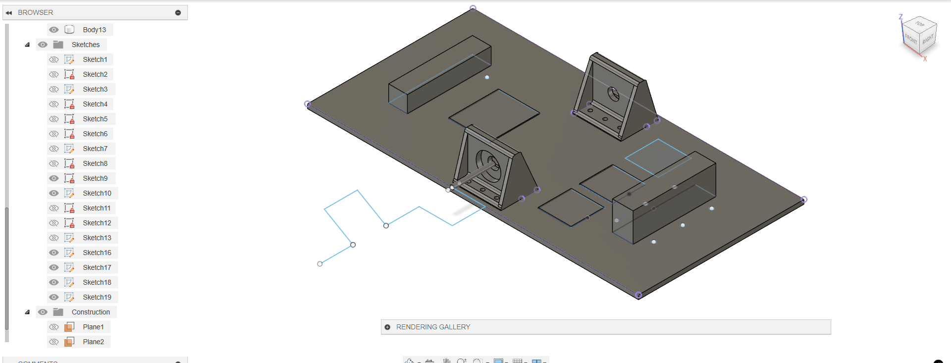
As u see in the right side of the image, we had in mind to use the hand crank mmechanism for the actuation but later moves to the gear mechanism for doing so.
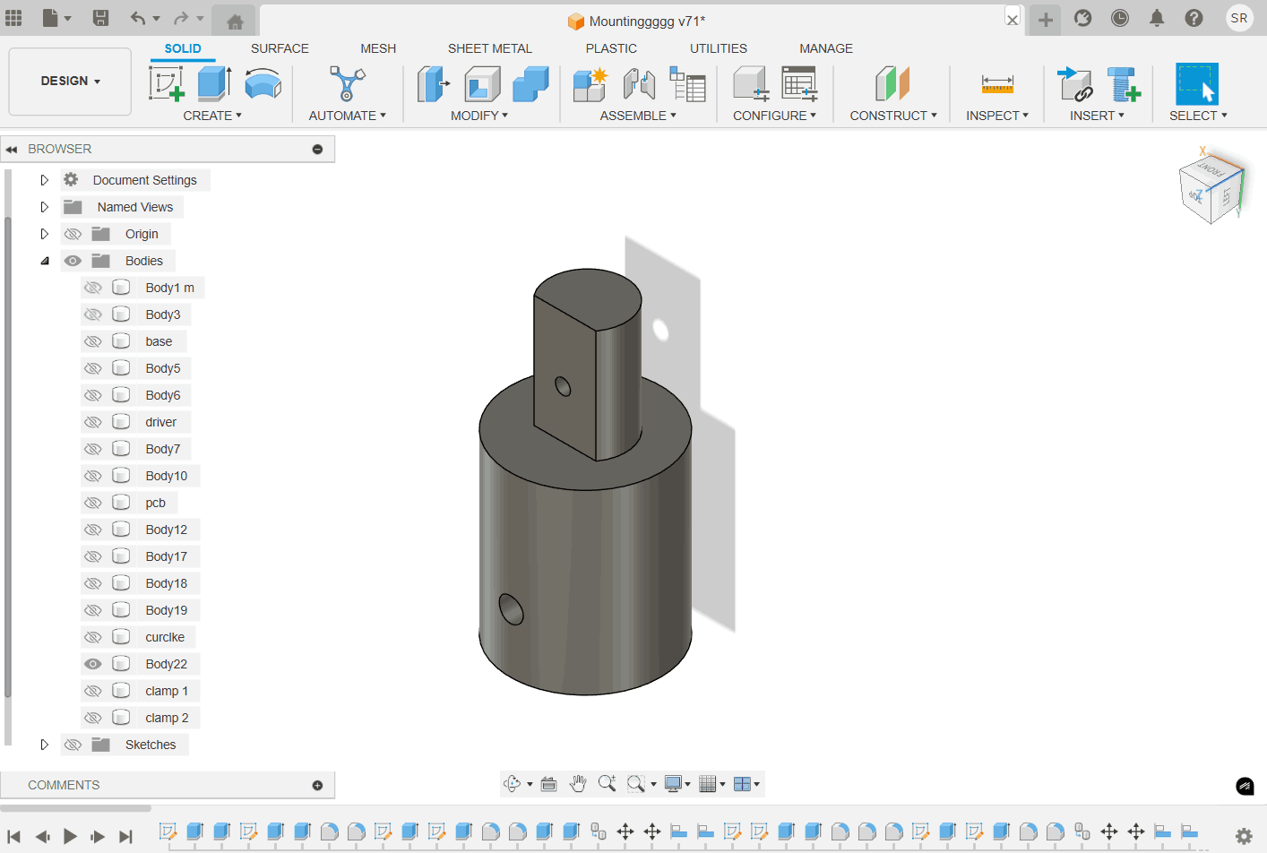
Mounting for the motor
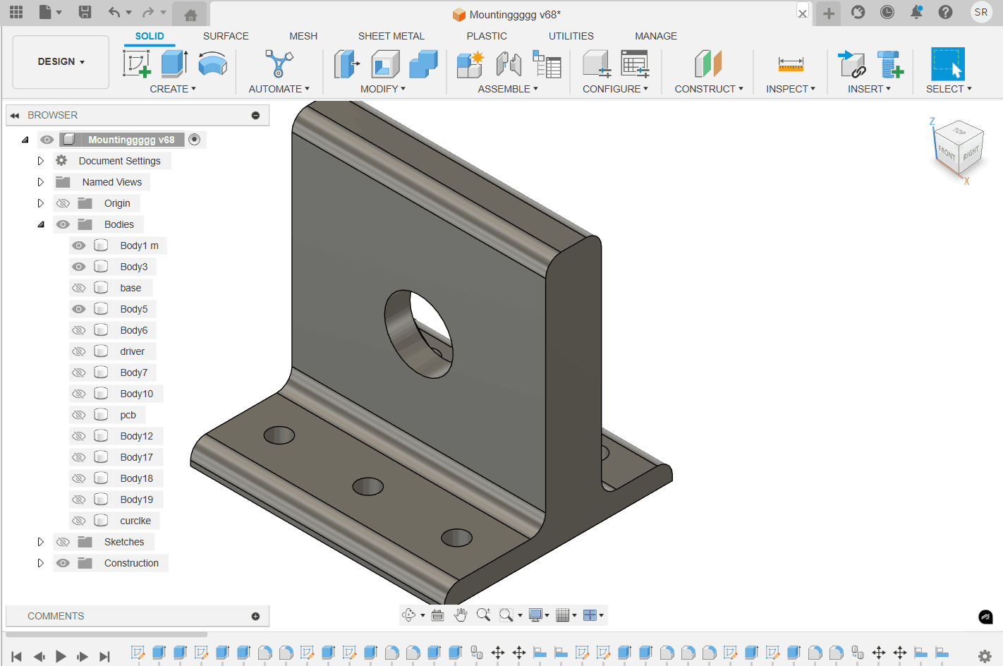
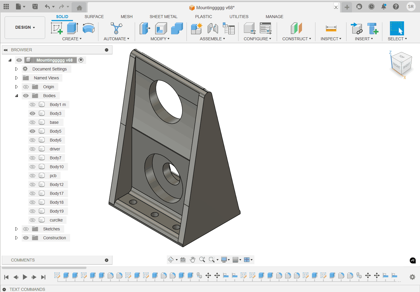
Extended mounting for the rod holding the mechanism as well.
Mounting for the motor
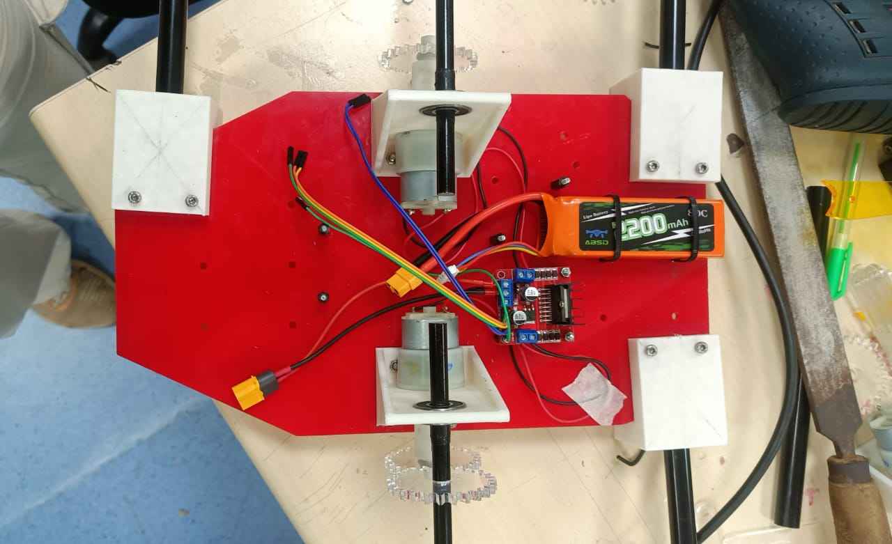
Motor to actuator Mounting
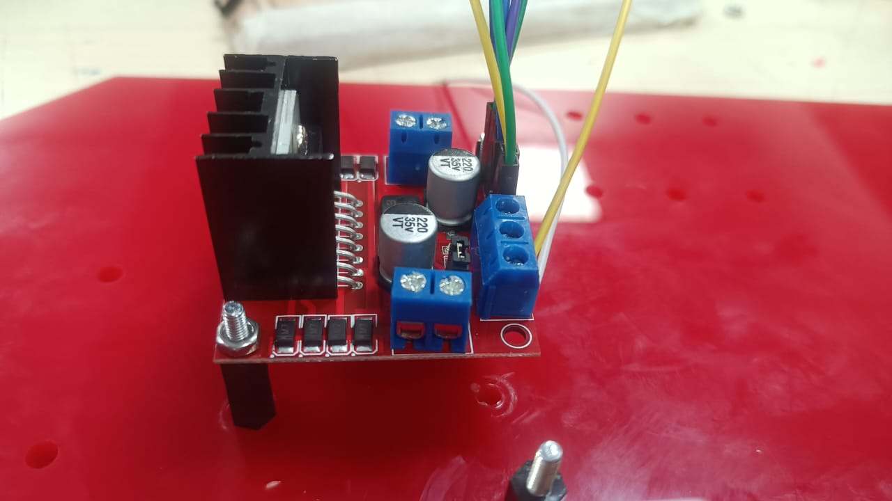
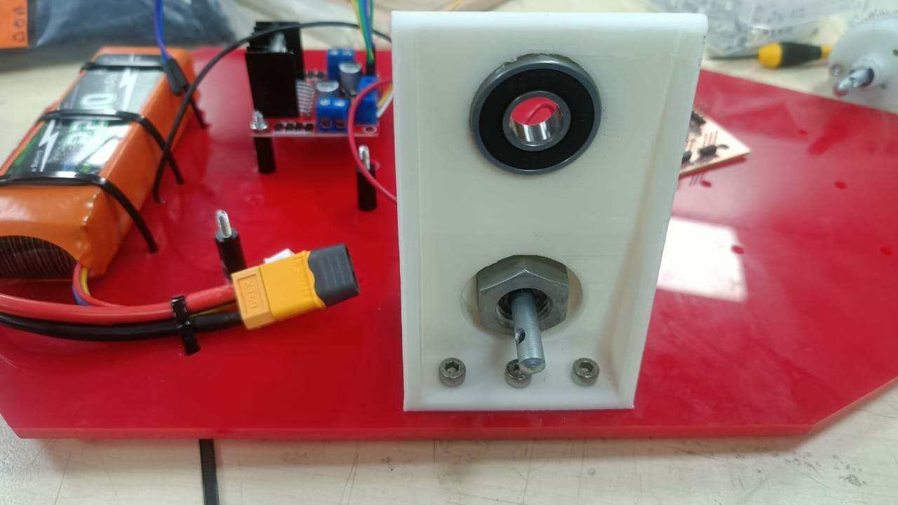
Mounting Electonic components: for which I used zip ties.
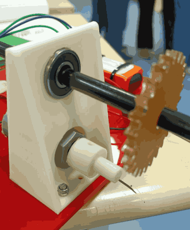
DFA. The centre of the rod mount: BEARING
Actuator: Gear mechanism
I never had a previous experience of gear mechanism. This I started building the gears on an open source platform: Evolvent Design. Where I learn types of gears and then, built a gear claculating the torque required for the speed transmission.
- Appearance:Teeth are on the outside of the gear.
- Use: Most common gear type. Used in gear trains, clocks, gearboxes.
- Motion: Transmits motion between parallel shafts.
- Direction: Rotates in the opposite direction of its mate.
- Appearance: A straight bar with teeth.
- Use: Converts rotary motion to linear motion (or vice versa).
- Example: Rack and pinion steering systems.
- Appearance: Teeth are on the inside of a circular ring.
- Use: Compact arrangements like planetary gear systems.
- Motion: Rotates in the same direction as the mating gear.
-
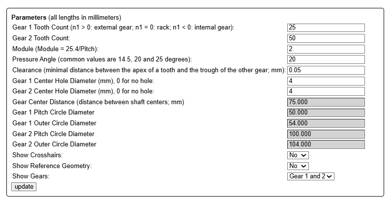
1. Gear 1 Tooth Count (25)
Number of teeth on Gear 1.
n1 > 0 means this is an external spur gear.
-
2. Gear 2 Tooth Count (50)
Number of teeth on Gear 2.
It’s double the teeth of Gear 1, likely for a 2:1 gear ratio.
-
3. Module (2)
Determines the size of the teeth.
Formula: Module = Pitch Diameter / Number of Teeth. A larger module = larger teeth.
-
4. Pressure Angle (20 degrees)
Common values: 14.5°, 20°, 25°.
Affects gear tooth shape and load distribution.
-
5. Clearance (0.05 mm)
Minimum spacing between gear teeth when meshing.
Prevents jamming or over-tight engagement.
- 6. Gear 1 Center Hole Diameter (4 mm)
Hole in the middle of Gear 1 (for mounting on a shaft).
- 7. Gear 2 Center Hole Diameter (4 mm)
Same as above, for Gear 2.
- 8. Gear 1 Pitch Circle Diameter (50.000 mm)
=
25
teeth
×
2
mm/module
=25 teeth×2 mm/module
- 8. Gear 1 Outer Circle Diameter (54.000 mm)
Adds extra size for gear tooth height.
- 9. Gear 2 Pitch Circle Diameter (100.000 mm)
=
50
teeth
×
2
mm/module
=50 teeth×2 mm/module
Gear Ratio Analysis
 Gear 1 (Driver)
- Tooth Count: 25
- Speed: 80 rpm(input speed)
- Tooth Count: 50
- Speed: ? (target output: 40 rpm)
Gear Ratio = Teeth on Driven Gear / Teeth on Driver Gear = 50 / 25 = 2
2. Speed Relationship
Speed is inversely proportional to gear ratio:
Output Speed = Input Speed / Gear Ratio = 80 rpm / 2 = 40 rpm
This matches the desired speed for our Strandbeest.
3. Torque Relationship
Torque is directly proportional to gear ratio:
Output Torque = Input Torque × Gear Ratio = T × 2
So the output torque is doubled, which helps in providing more force at lower speeds.
- Input Speed: 80 rpm
- Output Speed: 40 rpm → desired speed for Strandbeest
- Torque Boost: 2× increase at output
Conclusion:
Your gear setup is ideal for reducing speed and increasing torque — perfect for the
stable walking motion of a Strandbeest.
Friction fir for the shaft diamter was a major learning the process for which I referred to my inference form week 3 of Computer controlled cutting for the kerf.
DFA with gears: