Assignment Brief:
- Test design rules for the 3D printer (tolerance, overhangs, bridging, wall thickness, support structures).
- Design and 3D print a small, intricate object (few cm³) with complex geometry that can't be made subtractively
- 3D scan a physical object, refine the mesh, and optionally 3D print the scanned model.
3D printing
3D printing, also known as additive manufacturing, is a process of creating three-dimensional objects layer by layer from a digital model. Unlike traditional subtractive manufacturing (which removes material from a solid block), 3D printing adds material only where needed, making it highly efficient and customizable.
How 3D Printing Works
Common 3D Printing Technologies
Process: A thermoplastic filament is heated and extruded through a nozzle, depositing material layer by layer to form an object.
.png) Key Features:
Key Features:
- ✔ Affordable & widely available
- ✔ Works with various plastics (PLA, ABS, PETG, etc.)
- ✔ Easy to use with open-source software
- ✖ Lower resolution with visible layer lines
- ✖ Requires support structures for overhangs
Common Applications:
- Prototyping & product design
- Functional parts & enclosures
- Hobbyist & DIY projects
Process: A UV laser cures liquid resin layer by layer to form a solid object.
 Key Features:
- ✔ High resolution & smooth surfaces
- ✔ Wide variety of resins for different applications
- ✔ Minimal post-processing required
- ✖ More expensive materials than FDM
- ✖ Requires careful handling due to resin toxicity
Common Applications:
- Jewelry & dental prosthetics
- Miniatures, figurines, and artistic models
- Medical implants & biocompatible parts
Process: A high-powered laser sinters powdered material (plastic, metal, or ceramic) to create an object without the need for support structures.
- ✔ No support structures required
- ✔ Strong, functional, and industrial-grade parts
- ✔ Works with plastics, ceramics, and metals
- ✖ More expensive equipment required
- ✖ Requires post-processing for surface finishing
- Aerospace & automotive parts
- Medical implants & prosthetics
- End-use manufacturing
- Sturdy metal frame ensuring stability.
- Build platform labeled 220 x 220 mm, indicating the printing area.
- Textured surface for better adhesion during printing.
- Print head/extruder moves along the X, Y and Z axes, depositing filament layer by layer.
- Extruder branded "Creality" with a cooling fan.
- Touchscreen display connected via a cable.
- Allows users to control settings, load files, and monitor progress.
- USB or SD card slot for loading print files.
- The Ender 5 S1 has a sturdy aluminum frame, providing enhanced stability.
- The heated build platform is mounted on a reinforced Z-axis gantry, allowing for better layer adhesion and improved print accuracy.
- The print head assembly includes the extruder and cooling fan, responsible for depositing filament precisely.
- The X-Y motion system is located at the top, ensuring smooth and consistent movement across the print area.
- The build plate moves along the Z-axis while printing, ensuring high stability and accuracy.
- The four vertical guide rails support smooth bed movement and prevent wobbling.
- Orange UV-Protective Cover: Shields the liquid resin from ambient UV light and protects users from exposure to laser light.
- Resin Tank & Build Platform: The resin tank holds the liquid resin, and the build platform moves up and down during printing.
- Laser and Galvanometer System: A precise laser cures the resin layer by layer to create the final model.
- Touchscreen Interface: Allows users to control settings and start/stop prints.
- Cleaning and Post-Processing Station: The Anycubic Wash & Cure Machine is used to clean and cure finished prints for better durability. How It Works
- Preparation: The 3D model is sliced using Formlabs' PreForm software, which generates the support structures.
- Printing: A laser selectively cures the resin layer by layer while the build platform moves upwards.
- Post-Processing: Once printed, the model is removed, cleaned in isopropyl alcohol (IPA), and then UV-cured to enhance strength and stability.
- High-resolution prints with fine details.
- Smooth surface finish, ideal for functional prototypes.
- Capable of printing complex geometries and intricate designs.
- Requires post-processing (cleaning and UV curing).
- Resin can be expensive and requires careful handling.
- SLA printers are slower than FDM printers for large models.
- Print Accuracy: Whether the printed model matches digital dimensions.
- Structural Strength: How well the print withstands stress and usage.
- Surface Quality: Ensuring smooth finishes and proper layer adhesion.
- Printability of Complex Designs: Evaluating the printer’s ability to handle overhangs, bridging, and intricate geometries.
- Material Behavior: Understanding how different filaments behave under print conditions.
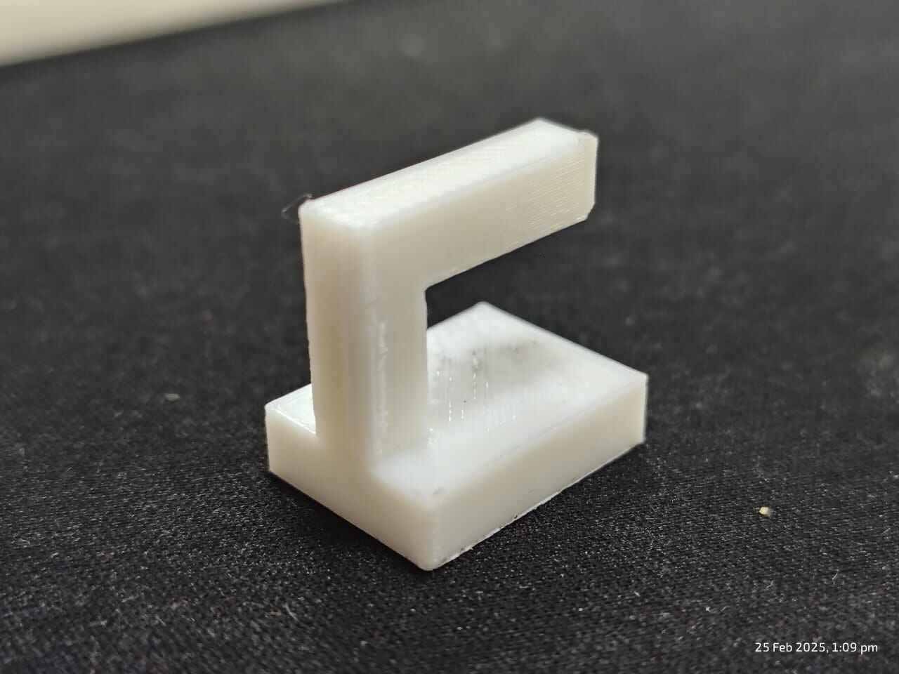
- Sagging & rough texture: Indicates printer limitations in handling unsupported overhangs.
- Drooping edges: Suggests insufficient cooling, causing filament to stay soft longer.
- Rough bottom surface: Shows difficulty in printing mid-air without support.
- Overhang Limit: Print quality drops beyond 45°-50°, requiring supports.
- Cooling & Speed: Higher fan speed and slower print speed improve stability.
- Support Structures: Essential for cleaner prints on overhangs exceeding 50°.
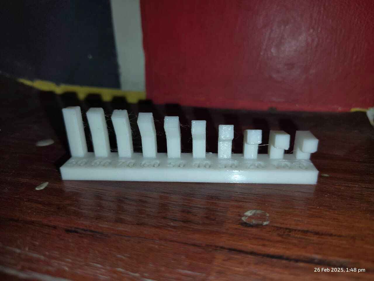
- 90° to 70°: Printed cleanly, showing good printer capability without supports.
- 60° and below: Noticeable drooping and stringing, indicating difficulty handling unsupported overhangs.
- 40° and 30°: Significant sagging and deformation, requiring supports for better results.
- 20°: Major failure, proving that angles beyond 45°-50° should use supports.
- Compare critical dimensions with the original CAD design.
- Ensure proper fit and tolerance for mechanical parts.
- The outer dimension of the printed cube is 20.02 mm, which is very close to the intended 20 mm.
- The inner dimension is 10.02 mm, slightly deviating from the intended 10 mm.
- This suggests that the printer's calibration is accurate but has a minor offset.
- Higher layer height (e.g., 0.3mm): Faster print, rougher surface.
- Lower layer height (e.g., 0.1mm): Smoother finish, longer print time.
- Post-processing: Sanding, vapor smoothing, and painting improve the finish.
- 3D Scanning: Uses laser, structured light, or photogrammetry to generate a digital 3D model.
- 3D Printing: Converts this digital model into a physical object by layer-by-layer material deposition (FDM, SLA, SLS, etc.).
- High Resolution & Accuracy: Captures fine details with an accuracy of up to 0.045mm.
- Multiple Scan Modes: Supports handheld HD scan, handheld rapid scan, fixed scan with or without a turntable.
- Wide Material Compatibility: Works well with dark and metallic surfaces with minimal preparation.
- Fast Scanning Speed: Captures up to 3,000,000 points per second in handheld mode.
- Portable & Lightweight: Easy to handle and transport, making it ideal for reverse engineering, design, and prototyping.
- Position the Calibration Board Correctly: Ensure it is flat and oriented as shown in the software.
- Hold the Scanner Perpendicularly: Keep it at a 90° angle to the board. Avoid tilting.
- Align the Scanner's Crosshair: Point it at the white box in the center of the board.
- Capture Images: Click to capture calibration data.
- Move Upward Steadily: Hold the scanner and adjust height from 430mm to 560mm, ensuring all boxes are checked.
- Device: EinScan Pro HD (Connected).
- Calibration: Last performed.
- Scan Mode: In Progress.
- Workflow Steps: Scan Mode → Scan → Post Processing → Measurement.
- Fixed Scan Uses a turntable and tripod for high-accuracy scans of stationary objects..
- Handheld HD Scan: Provides high-detail scans in handheld mode but requires markers for tracking.
- Handheld Rapid Scan: A faster, marker-free scanning method with lower precision than HD mode, useful for scanning large objects quickly
- Texture Scan: Captures color and surface details.
- Non-texture Scan: Selected (for scanning geometry only).
- Hybrid - Combines multiple alignment methods.
- Markers: Selected (uses physical dot-like markers for alignment).
- Features - Uses object’s geometric features for alignment.
- Classic - Standard scanning mode.
- Lightning: Selected (faster scanning).
- Lightning + Refine - Slower but higher accuracy.
- High - Sharpest details but slowest processing.
- Medium: Selected (balances detail and speed).
- Low - Faster processing but less detail.
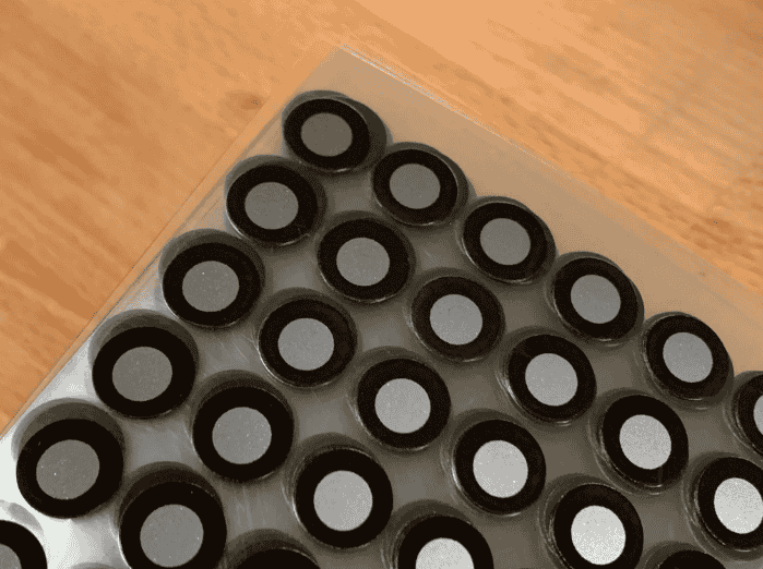
- Small, round stickers with a high-contrast reflective or non-reflective coating.
- Placed randomly on the object to provide consistent reference points.
- Commonly used in handheld 3D scanning for better alignment.
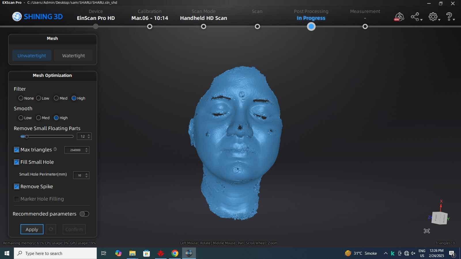
- Unwatertight / Watertight: Determines if the mesh has open or closed edges.
- Filter & Smooth: Adjusts noise reduction and surface smoothness.
- Remove Small Floating Parts: Cleans up disconnected mesh fragments.
- Fill Small Holes: Automatically fills minor gaps in the mesh.
- Marker Hole Filling: Eliminates marker positions from the final mesh.
- .STL – Common format used for 3D printing and CAD software.
- .OBJ – Widely used format that supports textures and materials.
- .PLY – Format that retains color and texture information.
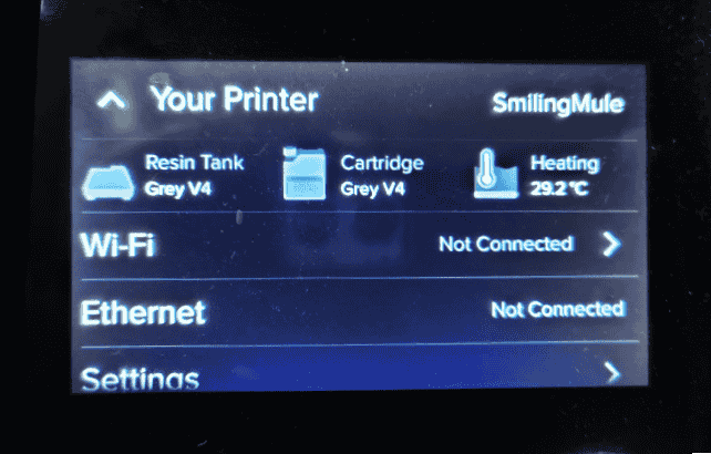
- Selected printer: "SmilingMule" (Form 2) (Status: Idle).
- Resin loaded: Grey V4.
- Tank contains: Grey V4 resin.
- Selected material: Grey V4 (suitable for general-purpose prints).
- Other available options: Black, Clear, Color, Draft, Grey Pro, White.
- Selected thickness: 0.100 mm (balanced speed and detail).
- Other options: 0.160 mm (faster), finer resolutions for more detail.
- Default print settings applied.
- Option to create custom settings for print speed, support structures, and tip shape.
- Orientation determines how the model will be printed in the resin printer.
- Proper orientation helps in reducing support requirements, minimizing print failures, and improving surface finish.
- Thus, I have placed the model within the build volume, and used the tools on the left allow for scaling, rotation, and movement adjustments.
- Resin prints require supports because the printer builds the model layer by layer, and unsupported overhangs can cause print failures.
- The software offers auto-generation of supports, but users can manually edit, modify, or adjust support density based on the print’s needs. My model is not very complex to I have used the auto-generation option for support generation.
- The right panel indicates if more supports are needed based on PreForm's print validation.
- The slicing preview allows checking each layer before printing, ensuring there are no missing or problematic layers.
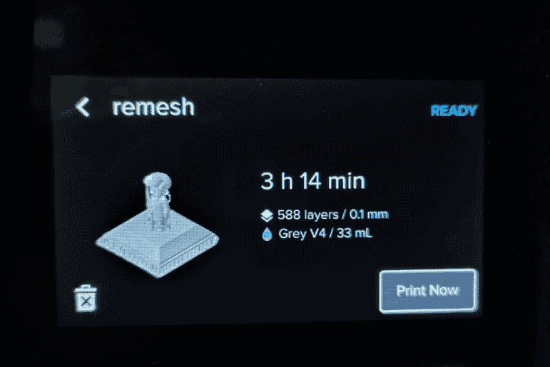
- Users can analyze the estimated print time, resin usage, and final model structure before sending it to the printer.4 hours, estimated time for my file print.
- The "Upload & Queue" button sends the sliced file to the Formlabs resin printer for printing.
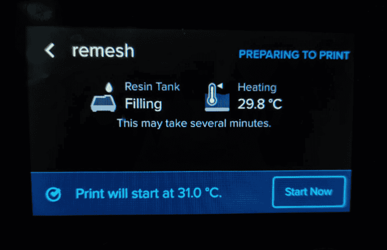
- The resin tank filling automatically while the printer continued heating to the required Temperature.
- The "Start Now" button became available once the printer was ready for the actual printing process.


Common Applications:
Overview of 3D Printing at Riidl FabLab
Riidl FabLab is equipped with multiple 3D printers that allow for rapid prototyping and manufacturing using various materials. This document provides a detailed SOP for each 3D printer available in the lab. Find the SOP here.
A. Creality 3D FDM Printer: Model Ender 3 v3 KE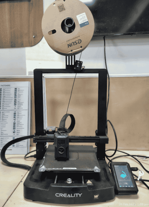
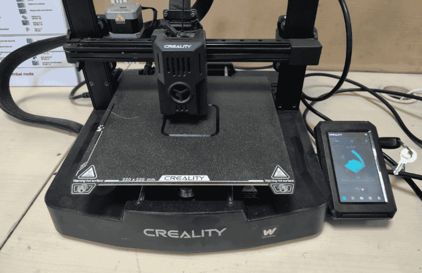
The Creality Ender 3 v3 KE is a Fused Deposition Modeling (FDM) 3D printer known for its precision, ease of use, and affordability. It is widely used for prototyping, product development, and hobbyist 3D printing.
1. Frame and Build Platform
2. Extruder and Nozzle Assembly
3. Touchscreen Display Interface and connectivity

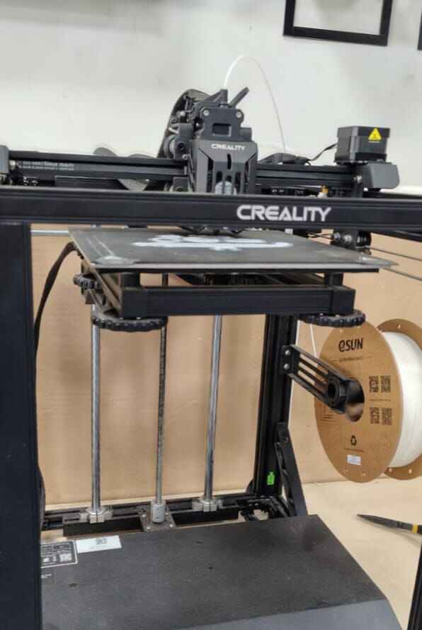
The Creality Ender 5 S1 is a Fused Deposition Modeling (FDM) 3D printer designed for high-speed and stable printing. It features a rigid cubic frame that enhances precision and reduces vibrations, making it suitable for industrial prototyping, product development, and functional part production.
2. Extruder and Nozzle Assembly
2. Motion System and Print Head
4. Bed Movement on Z-Axis
Comparison Between Creality Ender 3 v3 KE and Ender 5 S1
The Creality Ender 3 v3 KE and Creality Ender 5 S1 differ in design, stability, and printing capabilities. The Ender 3 v3 KE has a Cartesian-style structure, making it compact and budget-friendly, while the Ender 5 S1 has a CoreXY cubic frame that enhances stability, speed, and accuracy.
| Feature | Ender 3 v3 KE | Ender 5 S1 | Which is Better? |
|---|---|---|---|
| Design Type | Cartesian (single-arm) | CoreXY (cubic frame) | Ender 5 S1 (more stable) |
| Stability | Moderate | High | Ender 5 S1 (less vibration) |
| Print Speed | Standard (~150 mm/s) | High (~250 mm/s) | Ender 5 S1 (faster printing) |
| Print Accuracy | Good | Excellent | Ender 5 S1 (less wobbling) |
| Bed Leveling | Automatic (CR Touch) | Automatic (CR Touch) | Tie |
| Build Volume | 220 x 220 x 250 mm | 220 x 220 x 280 mm | Ender 5 S1 (slightly larger Z-axis) |
| Ease of Use | Beginner-friendly | Intermediate users | Ender 3 v3 KE (easier for beginners) |
| Price | Lower | Higher | Ender 3 v3 KE (budget-friendly) |
If you prioritize budget and ease of use, the Ender 3 v3 KE is a great choice. However, if you need stability, speed, and high print accuracy, the Ender 5 S1 is the better option. My personal prefernce for usage is Ender 5 S1 as it has given an higher precision in output in consideration of printing quality, minimized print failures and stabalized support.
A. SLA Resin Printer Form 2 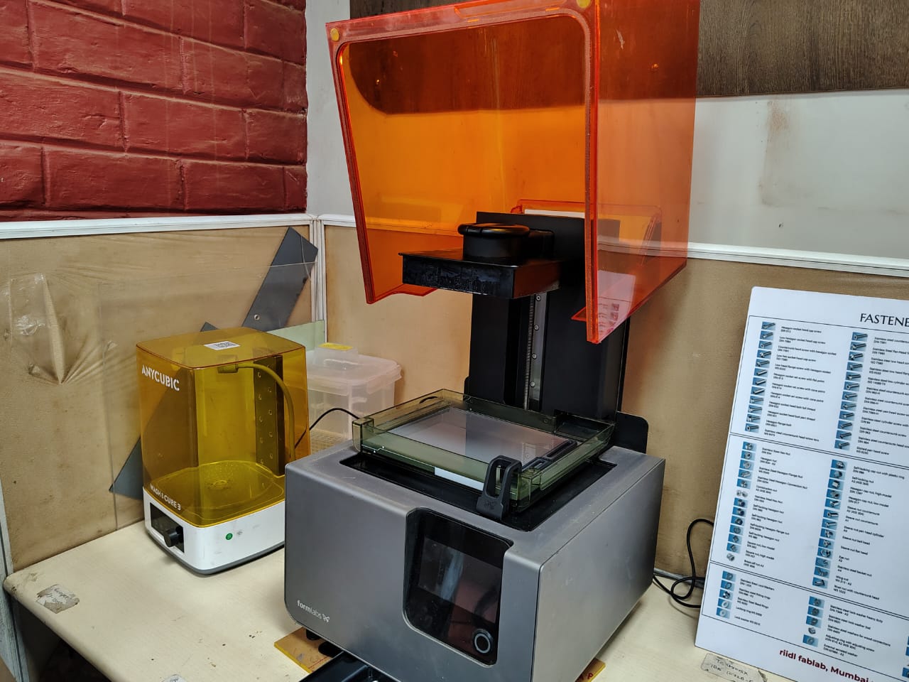
The Form 2 SLA (Stereolithography) Resin Printer is a high-precision 3D printer designed for producing highly detailed and smooth surface finish prints using liquid resin. It is commonly used for applications requiring fine details, such as prototyping, jewelry design, dental models, and engineering components.
Components & Features3D Printer Design Rules & Testing
I performed all the necessary tests for the Creality 3D FDM Printer: Model Ender 3 V3 KE. I have mentioned the tests done below. Through this process, I gained hands-on experience in troubleshooting, optimizing printer settings, and understanding the nuances of Fused Deposition Modeling (FDM) technology.
1. Introduction to 3D Printing Testing Why is 3D Printing Testing Important?3D printing testing involves a series of controlled print experiments that help determine a printer’s capabilities and optimize settings for high-quality prints. Testing for 3D printers is crucial to ensure reliability, precision, and performance of prints. It helps identify:
A. Supports & Unsupported Features
1. Overhang Overhang in 3D printing refers to parts of a model that extend beyond the previous layer without direct support underneath. Managing overhangs is crucial to prevent print failures and maintain structural integrity.
My learnings:
2. Bridging (Unsupported):
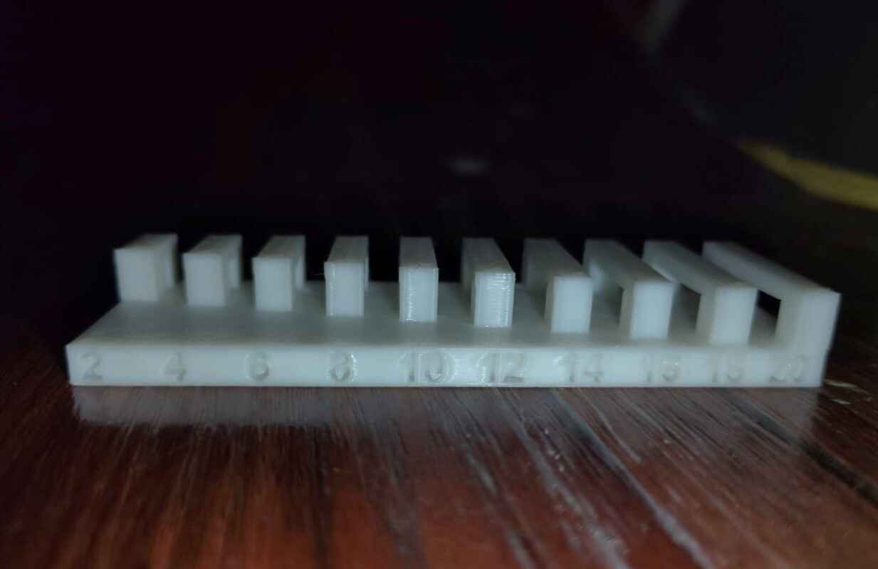
Assesses how well the printer can print filament across open gaps without sagging.
Bridging refers to the 3D printer’s ability to print horizontally between two points
without support structures. During bridging, the extruded filament spans across gaps,
relying solely on cooling and extrusion consistency
My learnings:
The printer maintains firm and clean bridging up to 12mm, meaning the extruded filament remains straight and properly adheres to both ends without noticeable drooping. Beyond 12mm, the bridging starts to weaken, sag, or show inconsistencies due to gravity pulling the molten filament downward before it solidifies. Factors like cooling efficiency, extrusion speed, material type, and print temperature could influence this result.
3. Unsupported Angle:
Determines the maximum angle that can be printed without support. Unsupported Angle
refers
to the steepest angle at which a 3D printer can successfully print without using support
structures. When the angle exceeds a certain threshold (typically around 45° to 60°),
the
filament starts drooping due to gravity, leading to poor surface quality and failed
prints.
Proper cooling, slower print speeds, and lower layer heights can help improve overhang
performance at steeper angles.
My learnings:
4. Clearance:
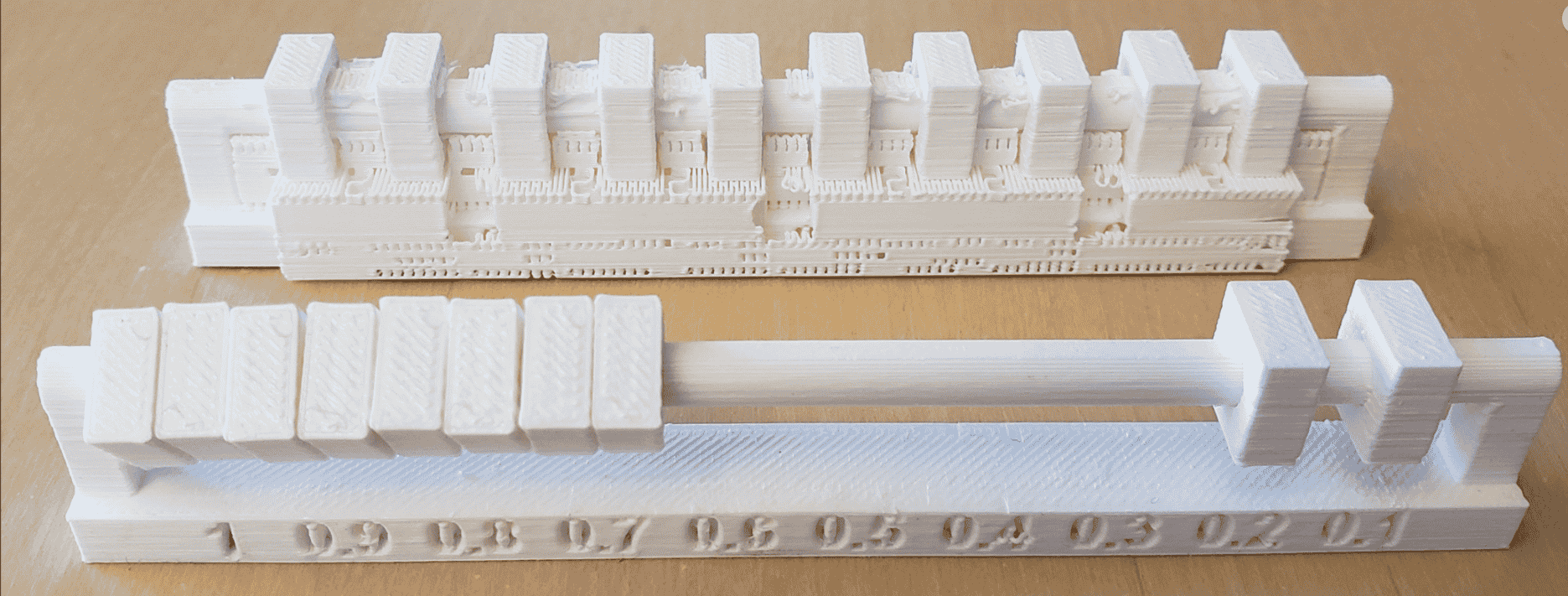
Evaluates the gap required for moving parts to function correctly after printing.
Clearance
in 3D printing refers to the intentional gap left between two parts to ensure proper
movement or separation after printing. It is crucial for assemblies, hinges, or
interlocking
parts. If the clearance is too tight, parts may fuse together; if too loose, they may
not
fit as intended. Optimal clearance depends on the printer's precision and material
shrinkage, typically ranging from 0.2mm to 0.5mm for FDM printing.
B. Structural & Dimensional Tests
1. Dimensional Tests
This tests verify the accuracy of the printed object:
Performing these tests helps optimize print settings, material selection, and post-processing for high-precision and reliable prints.
Dimensional Accuracy test
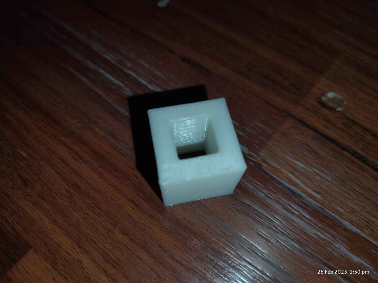
Outer dimension is 20.02 mm
.jpg)
Inner dimension is 10.02 mm
.jpg)
2. Surface Finish:
Assesses layer visibility and overall print smoothness. Surface Finish refers to the texture and quality of the outer surface of a 3D-printed object. It is influenced by layer height, material, print speed, and post-processing techniques. Different materials also impact the finish—PLA provides a smooth texture, while ABS can be acetone-smoothed for a glossy look.
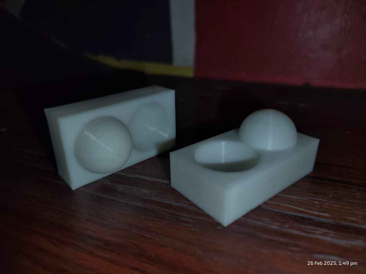
My learnings:
The ideal surface finish depends on the object's aesthetic, functionality, and application.
3. Infill Density & Pattern:
Infill Density refers to how much material is inside a 3D-printed object, measured in percentage (%). A higher density (e.g., 50%-100%) makes the object stronger but increases material usage and print time, while a lower density (e.g., 10%-20%) saves material and is suitable for lightweight parts.
Infill Pattern determines the internal structure of the print. Common patterns include Gyroid (strong and lightweight), Triangular(rigid and durable), Honeycomb(efficient and balanced), and Line (fast but weak). The choice depends on the required strength, flexibility, and material efficiency of the print.
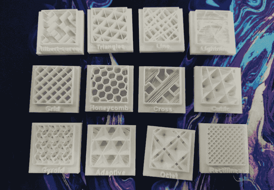
My learnings:
Through discussions with professors and hands-on experience,
I
learned that infill patterns play a crucial role in the strength and functionality of
3D-printed objects. The gyroid pattern is the strongest, followed closely by the
triangular pattern, which I frequently use in my projects. On the other hand, the line
pattern is the weakest and is best suited for support structures where minimal strength
is required.
Selecting the right infill pattern depends on the specific requirements of a print. Weak
patterns like line can be used for supports, while stronger patterns such as triangular
or gyroid are ideal for objects that need durability and structural integrity.
5. 3D Printer Calibration Test: Analyzing Print Quality and Performance
The purpose of this test was to evaluate the performance of a 3D printer by printing a standardized
calibration model. The model includes various geometric and functional tests to assess print
accuracy, bridging capabilities, tolerance handling, and stringing issues. This allows for
fine-tuning printer settings for better quality and reliability.
Test Model Overview:
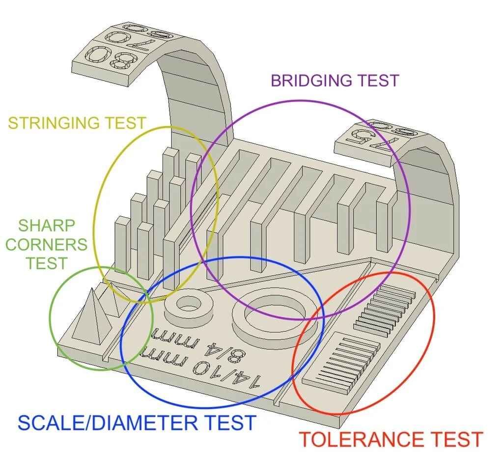
Analysis of Results:
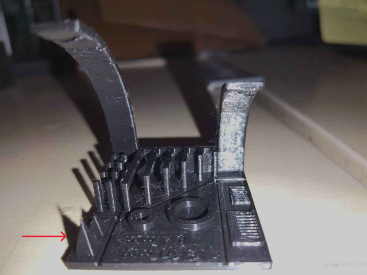
My learnings:
| Test Feature | Expected Result | Actual Result | Possible Fixes |
|---|---|---|---|
| Bridging Test | Smooth, sag-free bridges | Visible sagging and deformation | Increase cooling, lower temperature, reduce bridge speed |
| Stringing Test | No filament strings between pillars | Minor stringing observed | Increase retraction distance, lower temperature, adjust travel speed |
| Sharp Corners Test | Well-defined sharp edges | Slight rounding of corners | Reduce jerk and acceleration settings |
| Tolerance Test | Precise fitting of test gaps | Small gaps difficult to fit | Adjust flow rate (extrusion multiplier), ensure proper steps/mm calibration |
| Scale/Diameter Test | Accurate measurements matching the digital model | Slight deviations from expected dimensions | Calibrate steps/mm in firmware for correct scaling |
This test print highlights key areas where adjustments can be made for improved print quality. Primary focus: Improving bridging, reducing stringing, and fine-tuning dimensional accuracy. Modify temperature and retraction settings for cleaner prints. Fine-tune acceleration and jerk for sharper corners. Calibrate steps/mm for accurate scaling.
3D Scanning and Printing
3D Scanning and Printing is a process that involves capturing the shape and dimensions of a physical object using a 3D scanner and then recreating it using a 3D printer. Its like scanning an object and recreating its original version.

This technology is widely used in reverse engineering, prototyping, medical applications, and customization.
Overview of 3D Scanner at Riidl FabLab
Shining 3D EinScan Pro HD

The Shining 3D EinScan Pro HD is a professional handheld 3D scanner available at the Riidl Fab Lab. It is designed for high-precision scanning with fast speed and excellent versatility. It is manufactured by Shining 3D Tech Co., Ltd., based in Hangzhou, Zhejiang, China. This scanner is well-suited for applications requiring precision, such as industrial design, reverse engineering, and digital preservation.
Using EXScan Pro for 3D Scanning
Download the EinScan Pro 2X & HD Series scanner from the link attatched here. EXScan Pro is the proprietary 3D scanning software developed by
Shining 3D to operate the EinScan Pro 2X & HD Series scanners. This software provides an intuitive
interface for scanning, aligning, and processing 3D models with high accuracy. It supports various
scanning modes, including handheld and fixed scanning, allowing for flexibility based on the
object’s size and detail requirements.
Download from here:

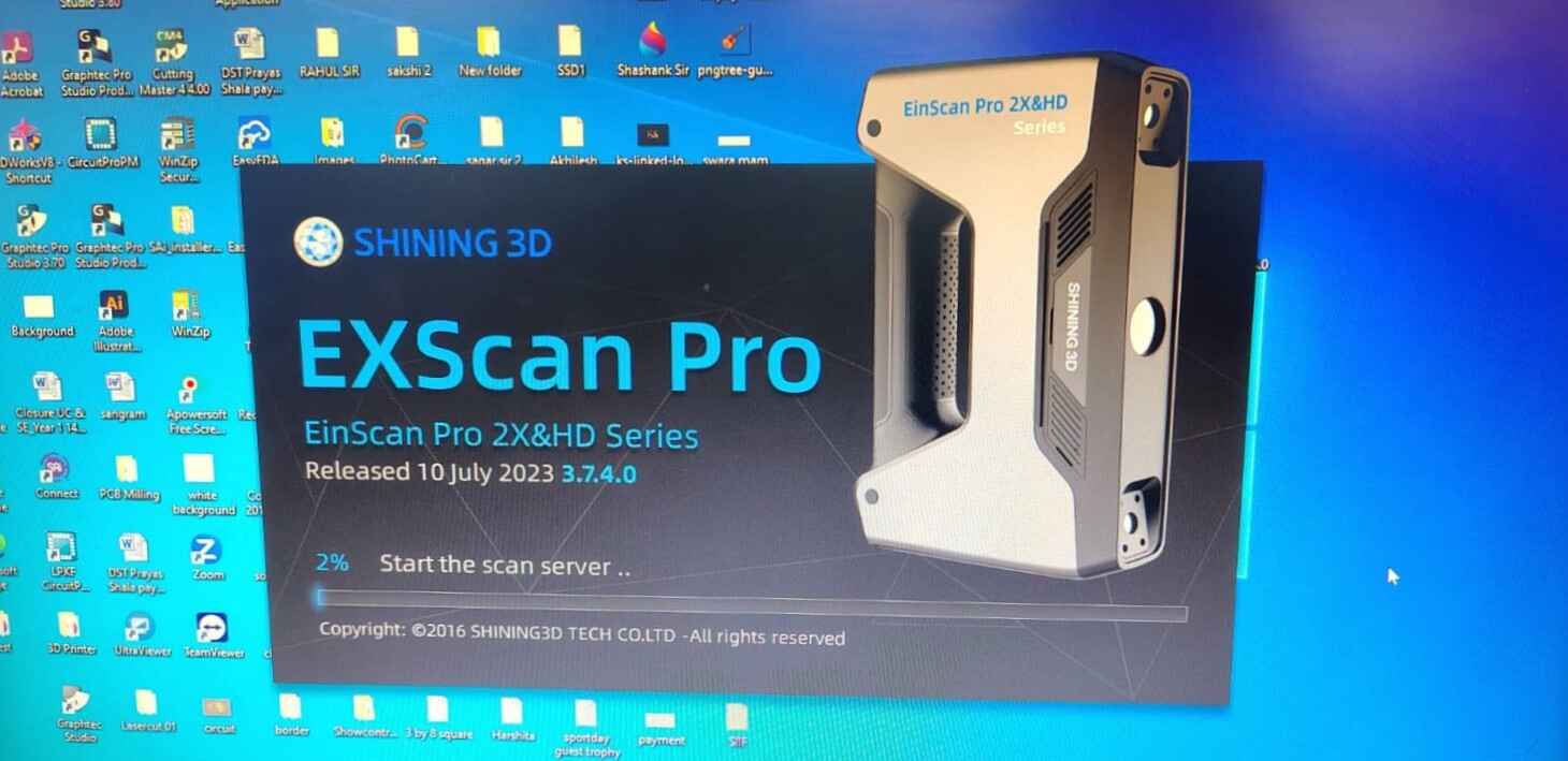
Launch EXScan Pro (Version 3.7.4.0):
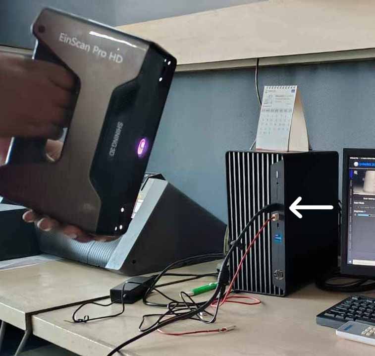
Attatch the USB pin to the system:
EinScan Pro HD Calibration Guide:
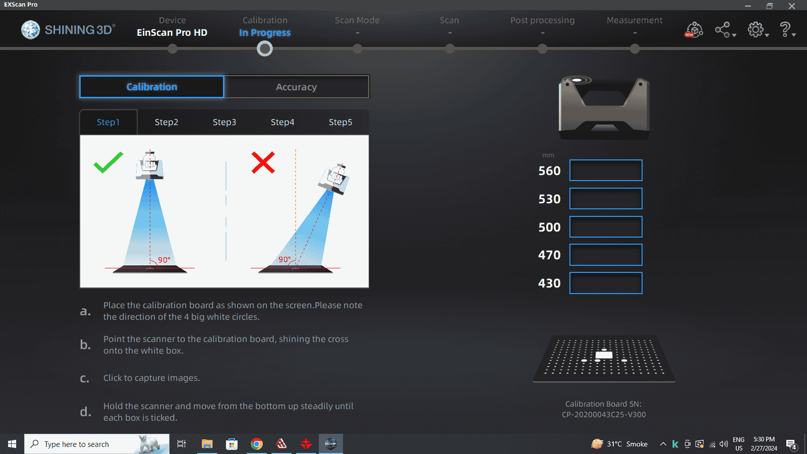
The calibration process ensures precise scanning accuracy and proper alignment. Follow these steps to calibrate your scanner for optimal accuracy:
Note: Since my scanner was pre-calibrated, I directly proceeded with scanning without performing the calibration process.
Scan Mode Selection:

I went forward with selecting the Handheld Rapid Scan for scanning as I wanted to scan a Large pot and make an attempt to scan my face.
Select folder to save file


Interface for setting up a new project in the Handheld Rapid Scan mode:

Select Texture:
Select Mode of Alignment:
Operation Mode:
Select Resolution:
In the settings I have prioritize speed and marker-based alignment, using non-textured data at a medium resolution. The Lightning mode is selected for faster processing, making it ideal for scanning objects where rapid data capture is preferred over extreme precision. The intention of this set-up is Scanning a big pot with markers.
Sticking Markers before 3D scanning:
Markers used in 3D scanning are small, high-contrast reference points that help the scanner track the object’s position accurately. These markers are especially useful when scanning objects that lack distinct geometric features or when using marker-based alignment.
Adhesive Circular Markers

Press the Button and start Scanning:
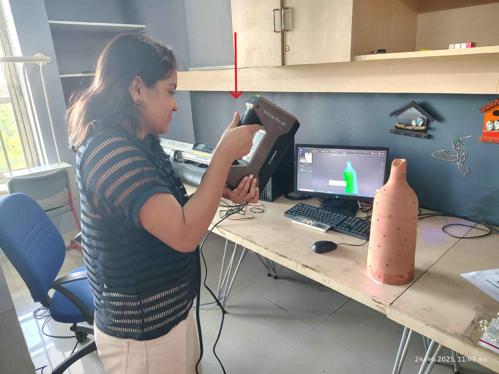
3d Scan every segment and use markers as reference:

Post-processing stage:

In the post-processing stage, refining the 3D mesh. The mesh is in "unwatertight", meaning it has open edges. The software is set to remove scanning artifacts like floating parts, holes, spikes, and marker positions. Click Apply with the final settings as in the image.
Exporting scanned data.:
For printing the 3d scanned object select the Mesh Files (3D Model Formats). I exported the file as STL. There are other formats of exporting of which some are:
Further Learning: 3d Face Mask
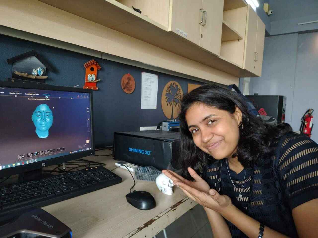
I loved the 3d scanning process. With the help of my mentor, Akhilesh Zambre and friend Sharvari Akerkar, I performed the 3D scanning of my face. I build a 3D mask of my face.Press the Button and start Scanning:
3d Scan every segment and use markers as reference:
3D-printing on Creality 3D FDM Printer: Model Ender 3 v3 KE
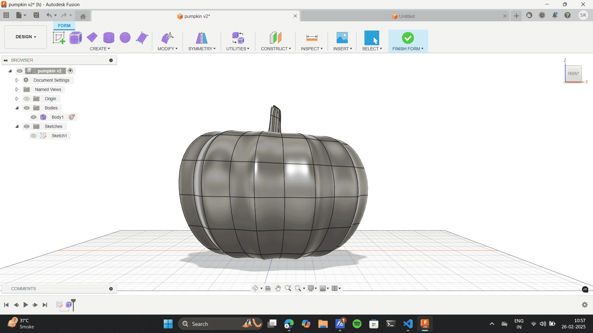
The goal was to design and 3D print a small object that could not be easily manufactured using subtractive techniques. I chose to model a pumpkin in Fusion 360, incorporating organic curves and internal hollows that make it challenging to produce through traditional subtractive methods like CNC milling or laser cutting.
Start new sketch:
.png)
Create> Spline> counter spline:
.png)
Create> Form> Revolve:

Below Settings for revolve:

Select lines of symmetry on the vertical plane and inner depth of 20mm:
.png)
Clear symmetry:

Double click top open layers> alt> pull inside:

Double click top open layers> pull inside:

Once the design is ready> modify> thicken:

Give a the desired thickness. I gave a thicness of 4mm

Slicer Siftware
Open Orca Software:

Open New project and Import file:

Orientate the Pumpkin and set the print quality

Select the strength settings as below

As the model is stable at the base, select auto-support:

Added a brim for the build plate adhesion:

Slice plate and export the G-code.

3D print Interface: select file from USB and select

Callibrate and print:
.jpg)
Final Print. Hero shot

Lamp Design
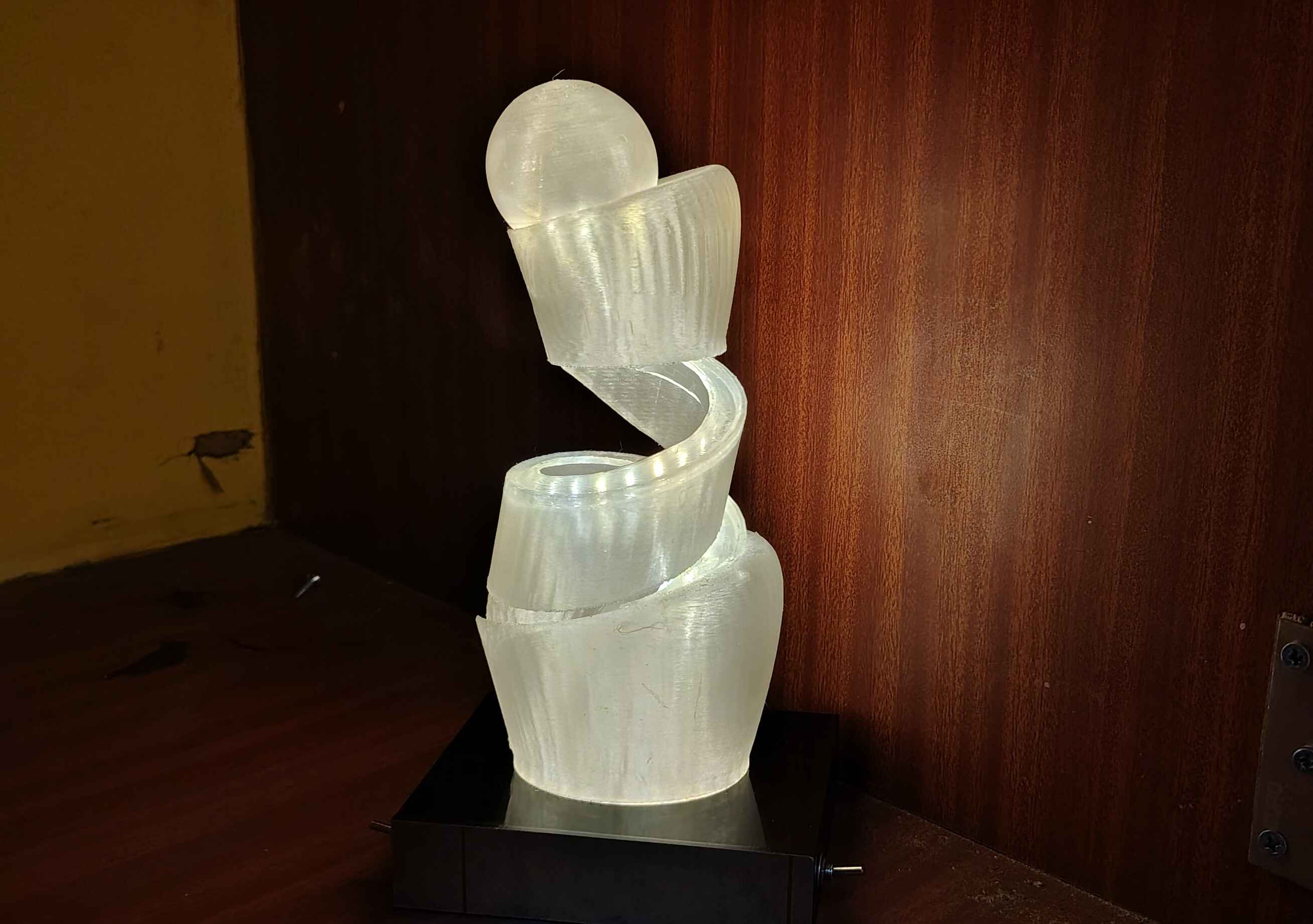
In a previous project that I did as my college Assignment, was designing a lamp which was build on taking inspiration from The Indian Mythology of Mahabharata. I went through a wholesome design process to ideate sketch and designing the lamp on Fusion 360.
Lamp Design on fusion 360
Final lamp render

As I went on printing, the strucure and for of this Lamp
was very intricate and so 3d printing the
lamp was a very lomg process. I explored different methods of 3d printing the Lamp.
Here, I used different support methods. I learnt that the tree support was the best for printing
intricate objects, plus to keep in mind the
density of of the supports also effects the post processing. The orientation of the lamp printing
on the bed also made a difference. I also used clear filament in one of the attempts I made
and kept the infill intact which drew a pretty Pattern on the exterior. Finally, I build
a lamp with my desired output. The model was build by me as a previous college assignment
so I am not adding a very detailed documentation here. However, to learn more about the project refer
to my behance link here
Very high density of supports could't be removed.

Post processing and wrinked filament at curves.

Internal infill clear filament.

Final Output of lamp, after the 3d printing I also integrated an Led strip on the
on the helical loop and an led light on the sphere on the top using a battery and an= toggle switch controlling the
the circuit.
3D-printing on Resin Printer Form 2
I printed a file I picked from Thingiverse to explore the step-by-step printing procedure of the Formlabs resin printer. This process involved preparing the model in PreForm, setting up the printer with the appropriate resin, and starting the SLA printing process. After printing, followed post-processing steps such as washing, curing, and support removal. Through this, I aimed to understand resin 3D printing workflows and best practices.
File Preparation
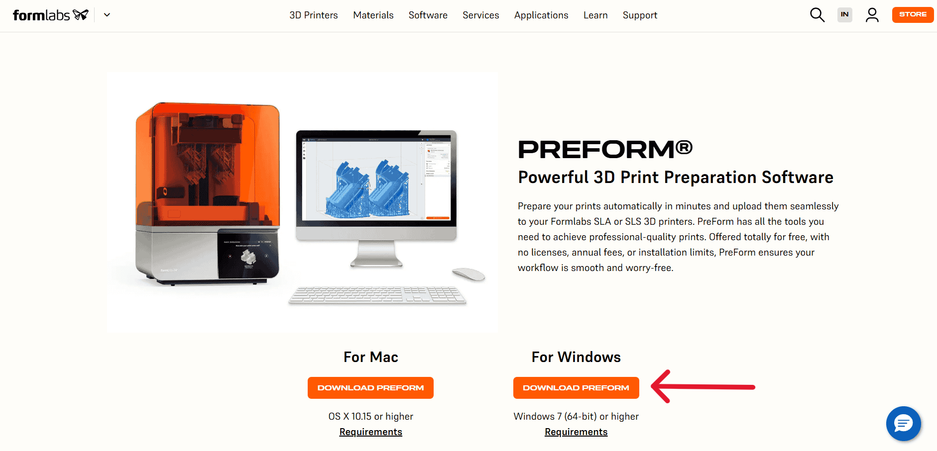
Download the PreForm Software:
To download the preform software refer to the link, here
PreForm Software: Open PreForm, and select the the printer model
.jpg)
1. Choose Printer
.jpg)
Orienting the Model:
.jpg)
Adding Supports:
.jpg)
Slicing & Layer Preview:
.jpg)
Printer Setup
Initializing the Printer:
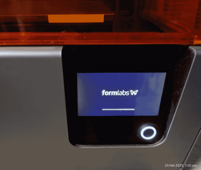
Formlabs logo appearing on the screen, indicating that the printer was powered on and booting up.
Checking Printer Status:
Connect the Wifi of the printer to the same Wifi to which the slicing software device is connected. This is important for Seamless File Transfer: When both the 3D printer and the slicing software device (PC or laptop) are connected to the same Wi-Fi network, print files can be transferred wirelessly without the need for external USB drives or manual intervention.
Loading the Print Job:
The file "remesh" was loaded, when you click on "Upload to Queue" on the Formlabs software.It also gave an estimating a print duration of 3 hours and 14 minutes with 588 layers and 33 mL of resin consumption. The "Print Now" option was available to start the process.
"Upload to Queue"
.jpg)
"Print Now"
Preparing the Printer for Printing:
Print Preparation Process:
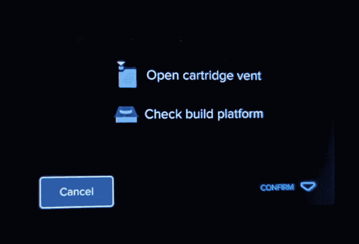
The Preparing the Printer for Printing, refers the user to open the cartridge vent and check the build platform before starting the print. This step ensured proper resin flow and correct build plate alignment.
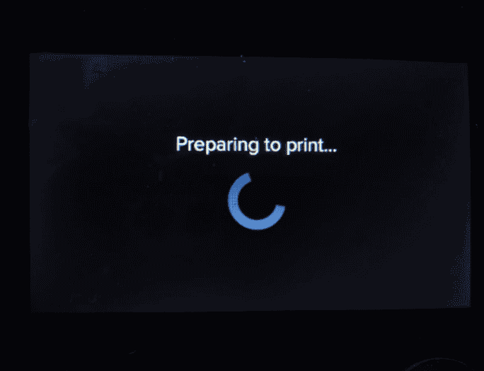
After clicking Confirm- It enters the "Preparing to print" stage, where it processed the job and checked for readiness.
Resin Tank Filling & Final Heating:
Opening printer Lid:

Checking Print:

Opening printer knob

SLA print:
.jpg)
Cleaning the Waste Resin:

Curing it:
.jpg)
Cleaning the Waste Resin:

Curing it:

Cleaning the Waste Resin:
.jpg)
Curing it:
.jpg)
Final Output
.jpg)
Hero Shots
3d Printing Pumpkin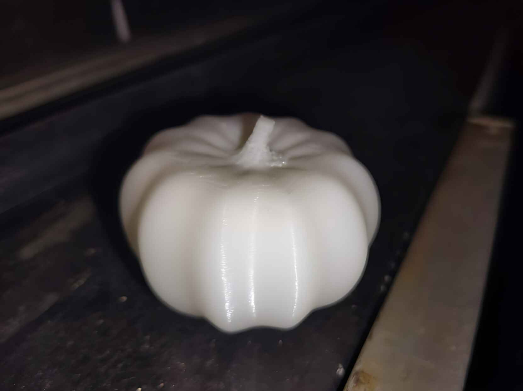 Resin Printing Ramesh
.jpg)
Project files
Mini 3D printing test
Pumpkin stl
3D Scanning
SLA Ramesh print- Google drive
FDM Printing Image Reference- Link
SLA Printing Image Reference- Link
SLS Printing Image Reference- Link