Week 16, System Integration
Assignment
- Design and document the system integration for your final project
Card dealer integration
Project Overview
Project Name: Card Dealer
Goal: Deal playing cards to start a game, with selectors for number of cards and players
Subsystems List
In current design, the following subsystems are used in the card dealer
- Input Devices:
- Three buttons, one to select # of players, one for # of cards, and one to start dealing
- Output Devices:
- 2x16 LCD screen, 2 NEMA 14 Stepper Motors, with I2C hood
- Processing Unit:
- RP-2040
- Two A4988 motor driver boards
- Power Supply:
- USB power brick which supports QC power (Qualcomm Quick Charge). Two connections. One for the RP2040, another for the custom QC power delivery board (to deliver 12V to the stepper motors)
- Interface/Networking:
- Internal communication with the LCD via an I2C connection
- Mechanical Structure:
- Combination of 3D printed and laser cut pieces
- External laser cut box with finger joints
- 3d printed housing for the LCD and buttons, mounted on the box
- Internal 3d printed frame to hold the components
- 3d printed roller to move the cards
Wiring and Electrical Integration
- Include wiring diagram (created in Fritzing/KiCad).
- Confirm:
- Voltage levels (3.3V / 5V)
- Correct pin mapping
- Common ground for all devices
-
Pull-up/down resistors if needed
-
Two custom boards
- QC power board
- Variable power selection via potentiometer
- Tunable up to 20V
- Project control board
- Input for 3 buttons
- I2C connection for LCD
- Connections for A4988 boards
- Sockets for RP2040, A4988s, and QC power board
- QC power board
The design and fabrication for these are completed. The KiCad files are available on the final project page.
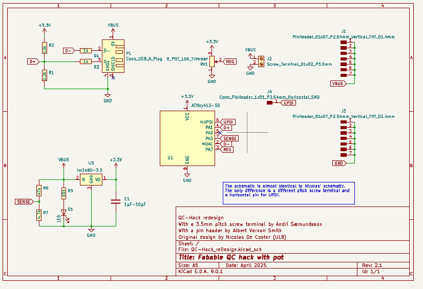
Schmatic for the QC power board
This board is based on a design from my instructor, who based his on a design from Nicolas de Coster.
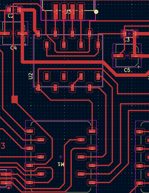
PCB design for the QC power board
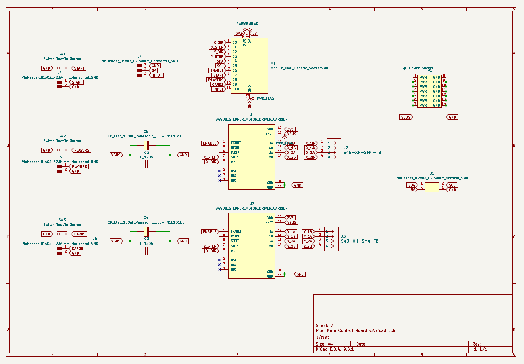
Schematic for project control board
I included buttons on the board, which are helpful for testing. For the project use, I included pins to connect external buttons
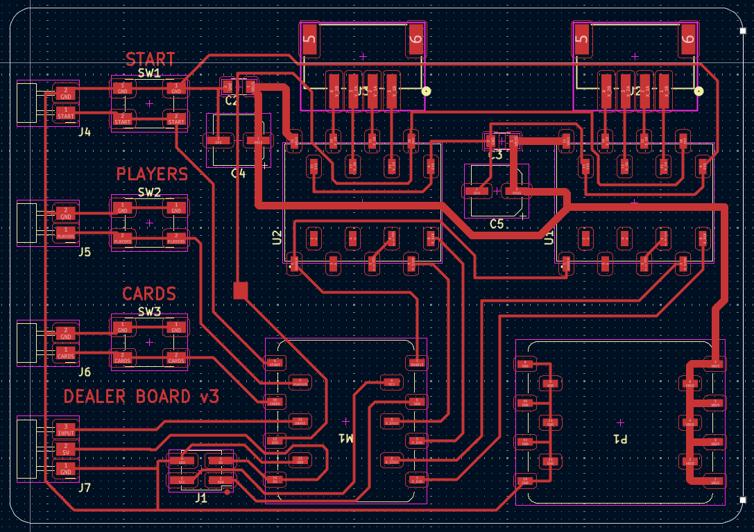
PCB design for the project control board
Data Flow / Communication Protocols
Define how each subsystem communicates.
| Source | Destination | Protocol | Purpose |
|---|---|---|---|
| Button 1 | RP-2040 | Digital | Select # players |
| Button 2 | RP-2040 | Digital | Select # cards |
| Button 3 | RP-2040 | Digital | Start dealing |
| RP-2040 | 2x16 LCD | I2C | Display out |
| RP-2040 | A4988 | Digital | Motor contol instructions |
| A4988 | Stepper motor | Digital | Motor movement |
Testing Plan
- Unit Testing:
- Test the control board responds to buttons (COMPLETED)
- Test the QC power board outputs 12V (COMPLETED)
- Test the LCD display output from RP-2040 (COMPLETED)
- Test that the board moves the motors via the A4988s (COMPLETED)
- Test the dispense of cards from roller (ONGOING)
- Integration Testing:
- Connect all components and see that they interacts (ONGOING)
- System Testing:
- Evaluate complete setup under expected conditions (IN PREPARATION)
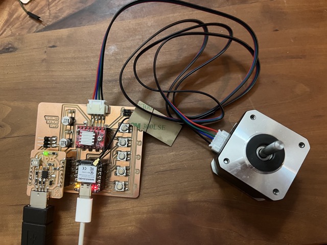
Testing motor operation
Mechanical Design and Assembly
Key aspects of mechanical assembly
- Fit components into the enclosure
- With several components, there is iterative design
- Functional needs
- Access to ports, buttons, display
- Robust attachments
- Motors held by screws
- Box held together with glue
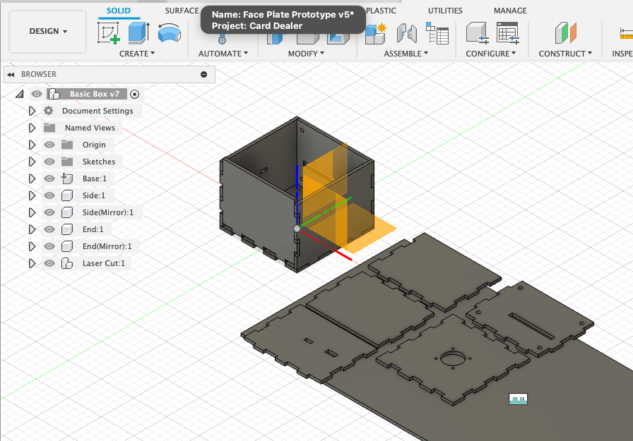
Main project box. Design with pieces laid for laser cutting
Using the manufacturing interface in Fusion allows for box design updates to be propogated to the parts for laser cutting. I started with a simple box, but needed to add mounting holes, wiring holes and other features.
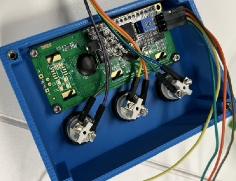
Wired LCD in control housing with buttons
At the moment, all the CAD and components are in flux. Each component has separate Fusion files. The best overview of it all together can be seen via my “HandCAD” drawings.
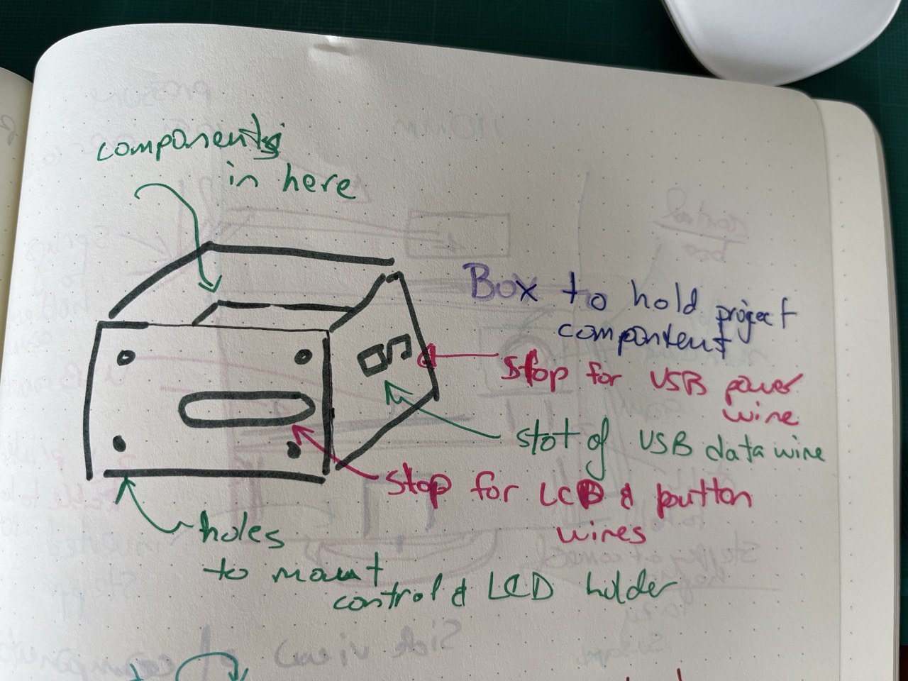
HandCAD: The project box
The project box is currently 110x110x90. It has holes for the two needed USB connections. Also mount points for a stepper motor at the bottom, and also to mount the LCD case.
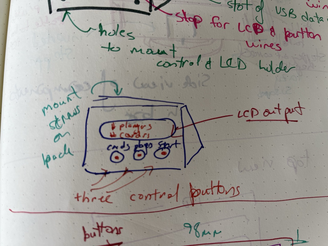
HandCAD: The front housing
The front housing for the LCD and buttons to control the card dealer. It mounts via screws onto the box.
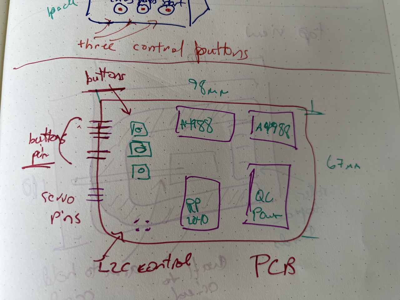
HandCAD: The control PCB
Similar to the KiCad images above, this is the PCB. The board is 98x67mm. This size partially dictated the size of the box.
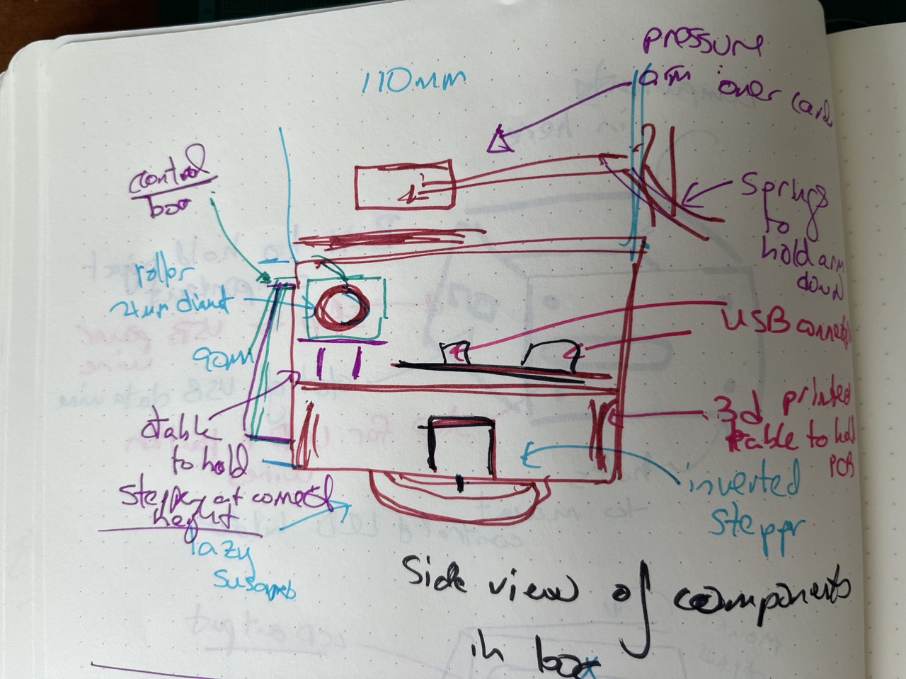
HandCAD: Side view
Components in the primary holding box in side view. There is a inverted stepper motor which slots into a lazy susan attached to the bottom of the box. There is a 3d printed table to hold the PCB above the motor, which has 27mm of clearance for the motor. The table is sized to be a exact fit in the box, so it will not move. There is another platform at the top of the box, where cards lie. Cards are held down by a pressure arm. Below the cards is a roller which will move the cards. This comes off a side mounted stepper motor. The control housing is mounted on the front of the primary box.
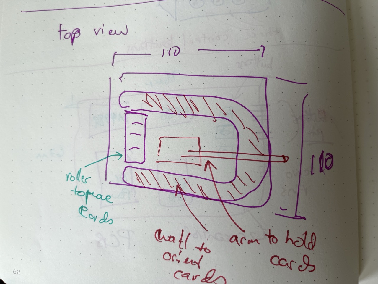
HandCAD: TopView
From the top, there is a slot, where the roller slightly protrudes. There are additional walls to align the cards (open on the ejection side). The pressure arm is pulled down by springs.
Programming and Control
The project relies upon a custom Micropython script. Libraries are needed to control the motors and LCD.
- Main Micropython code (COMPLETED)
- Motor Control Library (COMPLETED)
- Library to run LCD (COMPLETED)
All the code for this work is on the final project page
Iteration
During work, the project has relied upon prototypes and iterative design.
For the control board, there has been two major version, and additional minor updates in design. The initial board only could control one stepper motor, but two motors are needed in the current design. For minor changes, the I2C connection was changed from 3V to 5V in order to support the LCD.
The mechanical parts are designed in Autodesk fusion. This has relied upon parametric design, which allows for specific updates.
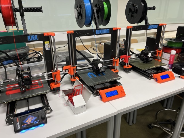
Three printers working on components for the project
Documentation
The final project requires the following.
- Wiring diagrams
- Photos of mechanical assembly
- Video of full system running
- Source code (with comments)
- Mechnical deesign files
- Explanation of how all parts work together
These will all be included on the final project page.