This week marks a transition into Computer-Controlled Cutting. Building on the 2D and 3D modeling fundamentals previously learned, the focus shifts towards translating digital vectors into physical prototypes using precision machinery.
1
Introduction
2
Computer-Controlled Cutting
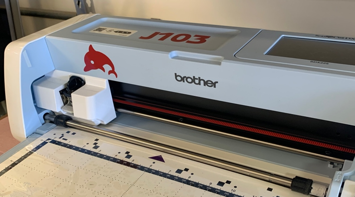
The objective for this week is to master both vinyl and laser cutting. For the vinyl cutting task, we utilized the ScanNCut SDX225 from Brother.
A critical concept addressed during this process is kerf: the amount of material lost due to the thickness of the cutting tool. To ensure a precise cut, the design must be a perfectly closed vector path.
Step 1: Design Reference
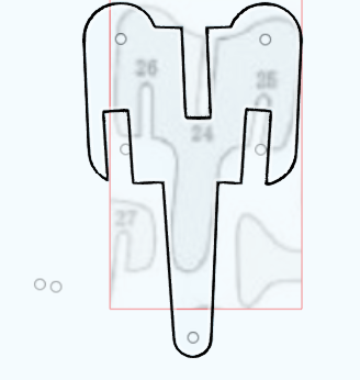
The workflow began with a clear visual reference of the icon. Using Layers (Ctrl+Shift+L), I imported the target design to serve as a guide for the proportions of the headband and earpieces.

Initial reference icon used for tracing and proportions.
Step 2: Headband Construction with Nodes
Instead of a simple line, the headband was constructed as a solid path. I used the Node Tool (N) to manipulate the Bézier curves, ensuring the inner and outer arcs were concentric and the endpoints perfectly aligned for a professional finish.
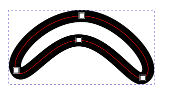
Editing the path nodes to define the headband's curvature.
Step 3: Structural Connectors
The link between the headband and the earpieces was created using Rounded Rectangles (F4). I adjusted the corner radius handles to create a "pill" shape that matches the structural aesthetic of the original design.

Creating the vertical rounded segments for the earpiece support.
Step 4: Detailing the Cushions
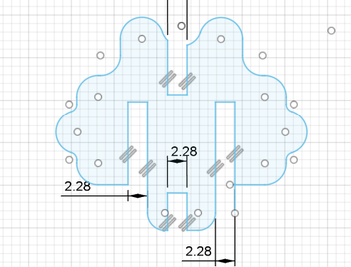
For the padded texture, I combined a main rectangular block with three overlapping circular shapes. This "cloud" effect was achieved by carefully aligning the small ellipses on the outer edge, creating the characteristic cushion appearance of the headphones.

Assembling the earpiece using primitive shapes.

Detailed view of the overlapping circles for the cushion texture.
Step 5: Boolean Union and Final Export
The final step was to select all individual parts and apply Path > Union (Ctrl++). This merged all overlapping geometries into a single, clean silhouette, essential for the vinyl cutter to follow a single continuous path without internal cuts.

Final unified vector ready for the ScanNCut plotter.
2
Computer-Controlled Cutting
The objective for this week is to master both vinyl and laser cutting. For the vinyl cutting task, we utilized the ScanNCut SDX225 from Brother.
A critical concept addressed during this process is kerf: the amount of material lost due to the thickness of the cutting tool. To ensure a precise cut, the design must be a perfectly closed vector path.
Design Process in Inkscape
Step 1: Design Reference
The workflow began with a visual reference. I imported the target design into a dedicated layer to guide the proportions of the headband and earpieces.
Initial reference icon used for tracing.
Step 2: Geometry and Nodes
The headband and connectors were built using the Node Tool (N) and Rounded Rectangles to ensure a smooth, professional silhouette.
Editing path nodes for the headband curvature.
Creating the vertical rounded segments.
Step 3: Detailing and Final Union
After adding the cushion texture with overlapping circles, I applied a Boolean Union (Ctrl++) to create a single continuous path, preventing redundant cuts.
Assembling the components with primitive shapes.
Detail of the overlapping circles for the cushion.
Final unified vector ready for production.
Steps to Use the Cutter
Initial Setup: Machine Preparation
The ScanNCut SDX225 was powered on and the home screen was accessed to begin the data retrieval process from the USB drive.
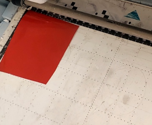
Loading: Material Placement
A piece of red vinyl was placed on the adhesive cutting mat. I ensured the material was flat to avoid bubbles that could interfere with the blade.
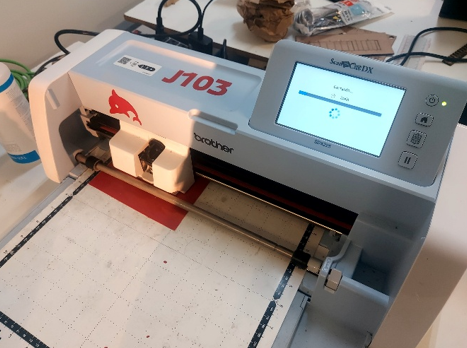
Cutting Process: Execution
The file was positioned on the scanned mat area using the touch screen. The machine then executed the cut using its auto-blade sensor.
Result: Weeding
Once the cut was finished, the excess vinyl was removed (weeding) to reveal the final headphone shape on the backing paper.

Final Application: Decal on Notebook
Using transfer tape, the vinyl decal was carefully moved from its backing to a notebook surface, ensuring proper adhesion and a clean finish.

3
Laser Cutting
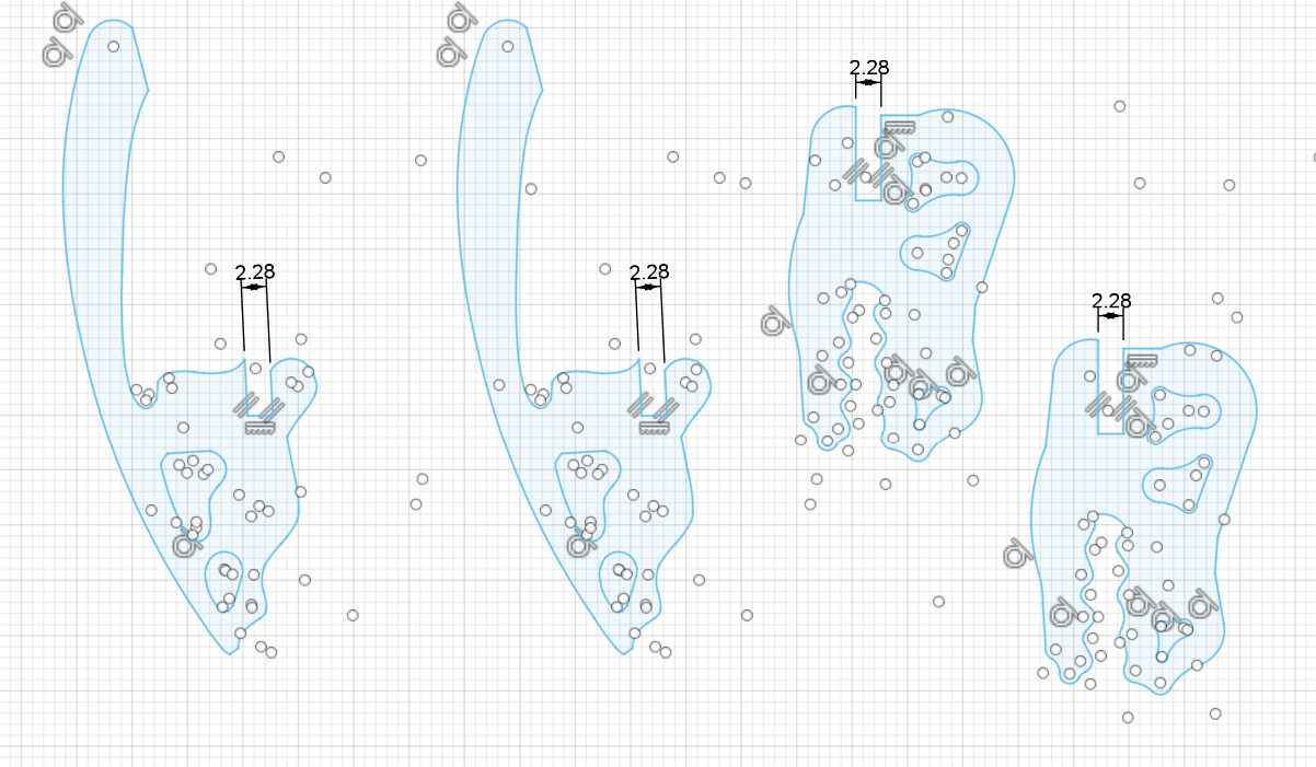
For the second part of the task, my idea was to create the skeleton of a dinosaur. To get a base idea, I searched for dinosaur puzzle ideas on Pinterest and used the image as a background guide in Fusion, using the sketch tool with lines and curves.
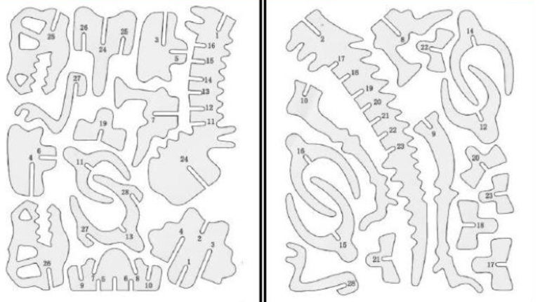
In Fusion 360, go to the "Insert" tab and select "Canvas", then select the plane and load the dinosaur skeleton image. Adjust the size and position of the image to fit your workspace.
In this image, you can see an example. The idea is to follow the same procedure with each of the bones in the base image. For larger parts, it's better to mentally divide the bone into two parts to make drawing easier.
Once we have a base to work on, it's necessary to use other tools to minimize errors, starting with using Fusion's constraints. We used the parallel function to find symmetry for the joint spaces, and based on the kerf tests, it was determined that a good joint space is 2.28mm.
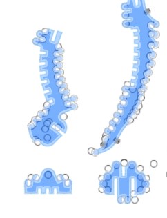
To create the dinosaur's spine, one way is to use Fusion's scale tool, selecting a piece, such as a vertebra, and adjusting it to be smaller or larger. Then, adjust the joint space to 2.28mm to ensure a proper fit.
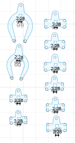
To make it parametric, it's necessary to avoid this adjustment always. One test to perform is to use the scale function on the entire design and observe how the different pieces behave. Another idea is to perform this scaling while keeping the 2.28mm parameter constant to ensure the joints.
Finally, the idea of creating a base is to make two configurations where the dinosaur skeleton is the same, but we can interchange some pieces, such as the head, to have different dinosaurs.
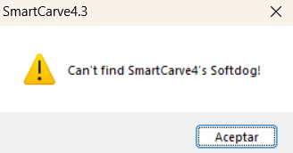
Problems with the Laser Cutter
The first issue was that the software for the laser cutter wouldn't install correctly on my computer, and I received the following message.
Once I managed to use the software on another computer and convert my files to the required format, the laser cutter did not recognize my file.
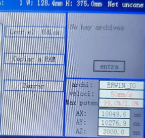
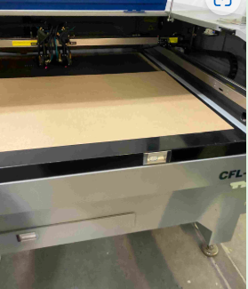
This problem was solved by using another computer and formatting the USB drive so that it could read my file correctly. Once the issue was resolved, the laser cutting work began, a crucial step in the process of creating the dinosaur skeleton.
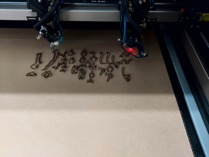
The final result was satisfactory, successfully obtaining the pieces of the dinosaur skeleton with precision and quality. Each component was meticulously cut, ensuring that they fit perfectly together. This process not only required attention to detail but also careful planning to ensure that all pieces were functional and aesthetically pleasing.
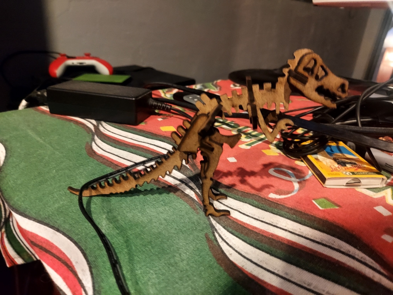
In the end, the pieces were ready to be assembled, allowing me to visualize the complete dinosaur skeleton. This project not only taught me about the use of laser cutting technology but also provided me with valuable experience in troubleshooting technical issues