1

Introduction

This week is dedicated to 2D and 3D modeling. The main focus has been the development of the casing to create a prototype concept for my final project, SafePath-RM.

To achieve this, I used SolidWorks for detailed design and Fusion 360 to model what a charging dock for my project would look like. Additionally, this week explains how to compress images and videos, ensuring that the documentation remains lightweight.

Software General Function and Application
SolidWorks Computer-aided design (CAD) software for solid and parametric mechanical modeling.
Fusion 360 Integrated tool that combines industrial and mechanical design, simulation, and manufacturing on a cloud platform.
Inkscape Open-source vector graphics editor.
GIMP Cross-platform image editor used for photo processing and web file optimization (size compression).
FFmpeg Open-source video transcoder that allows reducing multimedia file sizes while maintaining visual quality.
2

3D Modeling: SafePath-RM Casing

Below, I present the detailed workflow for the casing design. This guide is intended to be replicable by any beginner SolidWorks user.

Phase 1: Project Start

We begin by opening a New Document, selecting the Part environment, and choosing the Top Plane as our drawing base.

New Document

Creating a new file.

Part Selection

Selecting Part mode.

Top Plane

Choosing the work plane.

Phase 2: Base Drawing (Sketch)

We create a 44x50 mm rectangle and apply Sketch Fillet to smooth the corners before adding volume.

Rectangle

Rectangle dimensions.

Sketch Fillet

2D fillet tool.

Sketch Result

Finalized sketch result.

Phase 3: Volume (Extrude)

Using the Extrude tool, we set the value to 15 mm and observe how the flat drawing turns into a solid.

Extrude Tool

Accessing Extruded Boss/Base.

Extrude Menu

Setting depth to 15mm.

Extrude Result

View of the generated solid.

Phase 4: Smoothing (3D Fillet)

To improve the design, we use Fillet. We select the edges in the menu and validate the visual result.

Fillet Tool

Selecting the Fillet operation.

Fillet Menu

Radius configuration.

Fillet Result

Solid with rounded edges.

Phase 5: Cavity (Shell)

We apply Shell to hollow out the block, configuring the wall thickness for the electronics housing.

Shell Tool

Selecting the top face.

Shell Menu

Adjusting wall thickness.

Shell Result

Internally hollowed casing.

Phase 6: Strap Slot

We use Straight Slot to design the opening, defining a length of 27 mm and a width of 3 mm.

Slot Tool

Straight slot tool.

Slot Menu

Defining slot dimensions.

Slot Result

Positioned slot drawing.

Phase 7: Perforation and Completion

To finish, we apply Cut-Extrude. We review the preview and confirm the final result of the part.

Cut Tool

Extruded Cut operation.

Preview

Preliminary view before confirming.

Final Result

Finished casing, ready for use.

3D Modeling: Casing Lid

The lid was designed following the same parametric logic as the base. At this stage, using the Sketch Fillet tool is key to ensuring that the contour matches the casing perfectly.

Phase 1: Main Body

We start with a 50 x 44 mm rectangle. To smooth the corners in the sketch, we use the Sketch Fillet tool. This allows us to define precise radii before generating the solid.

Lid Sketch

Initial lid sketch (50x44 mm).

Sketch Fillet Tool

2D Fillet Tool: Sketch Fillet menu used to round the corners.

Sketch Fillet Result

Applying Sketch Fillet to all four corners.

3mm Extrude Menu

Extrusion menu set to 3 mm.

Result 3.1

Finished lid base solid.

Phase 2: Internal Fit Lip

On the internal face, we draw a second 44 x 38 mm rectangle. Again, we apply Sketch Fillet to maintain consistency and extrude 2.5 mm to create the relief that fits into the casing.

Second Sketch

Design of the adjustment rectangle (44x38 mm).

2.5mm Extrude Menu

Extruding the adjustment relief.

Final Lid Result

Finalized lid with the closing lip.

Assembly Process

This section details the assembly casing components using SolidWorks.

Phase 1: Project Initialization

To begin the assembly, we must create a specific environment that allows the interaction between multiple parts.

New File

Accessing the New Document menu.

Assembly Selection

: Selecting the Assembly template.

Phase 2: Inserting Components

We use the Insert Components tool to bring our designed parts into the assembly workspace.

Insert Tool

Activating the Insert Components tool.

Selection Menu

Selecting the casing parts from the browser.

First Component

Placing the base component.

Second Component

Positioning the second casing part.

Phase 3: Advanced Mating

To ensure perfect alignment, we utilize the Mate tool, focusing on the Profile Center advanced mate for the casing's geometry.

Mate Tool

Opening the Mate property manager.

Profile Center

Applying Profile Center for automatic alignment.

Final: Assembly Verification

The components are now fully constrained and aligned, forming the complete SafePath-RM casing.

Final Assembly

Final result of the casing assembly.

3

Modeling the SafePath-RM Induction Dock

In this section, we are going to build the induction charging dock from scratch.

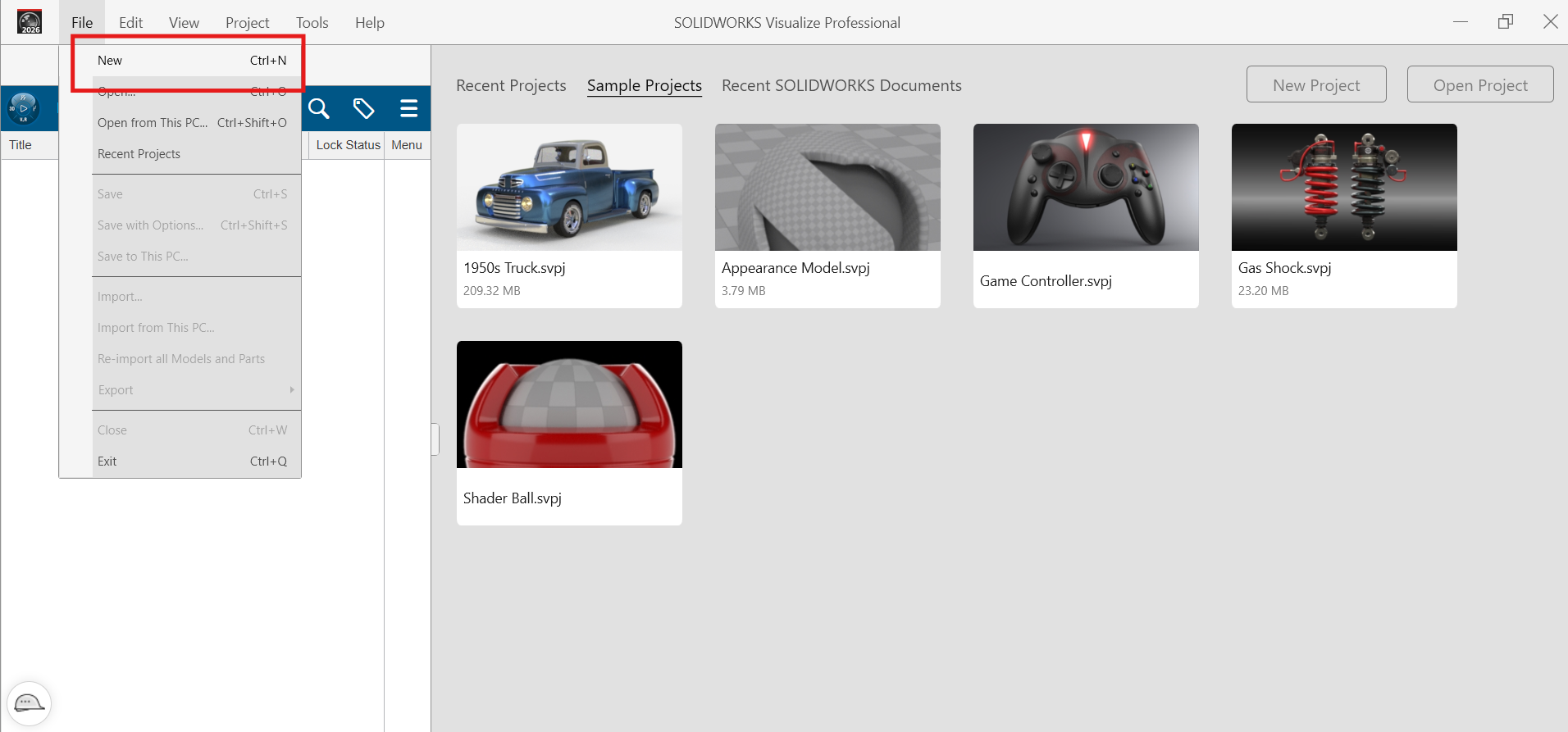
Step 1: Workspace & First Sketch

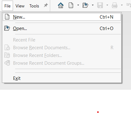
We'll start by opening a new design. In Fusion 360, everything begins with a sketch. 
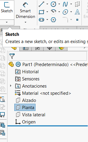
We'll pick the Top Plane (the floor) because we want our dock to sit flat on a table. 
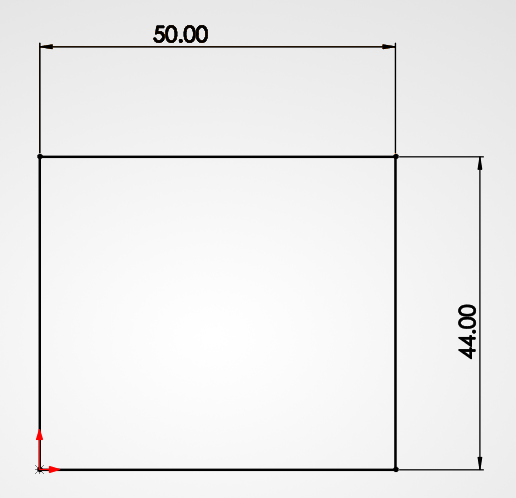
Using the Center Rectangle tool: it keeps everything centered on the origin, which makes the whole design much more organized.

New Design

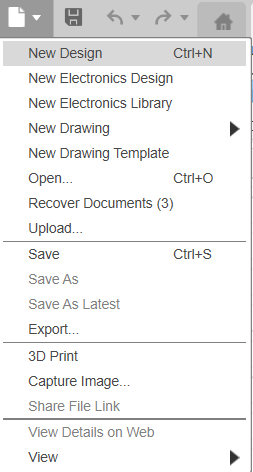
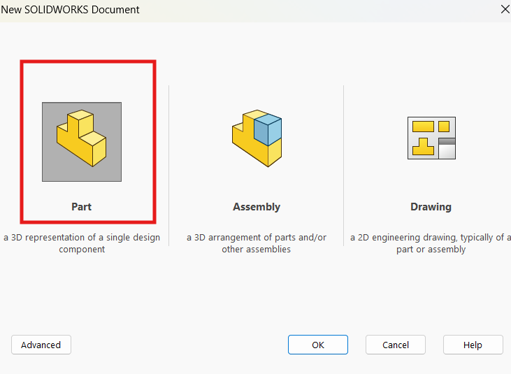
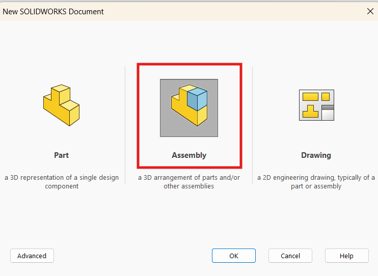
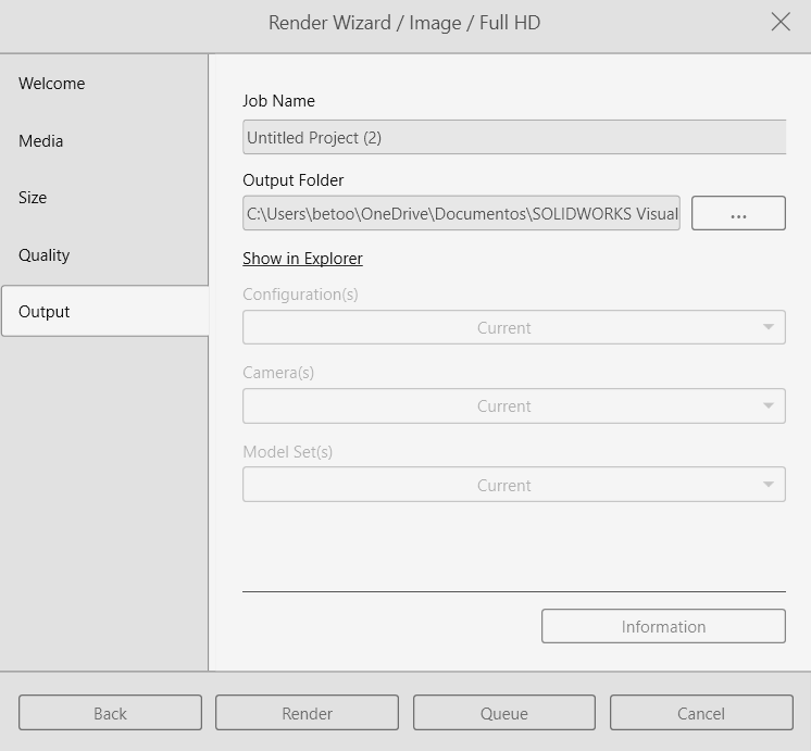
Starting a new design file.

Create Sketch

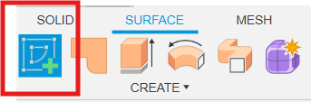
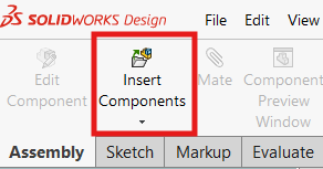
Selecting the 'Create Sketch' icon.

Rectangle Tool

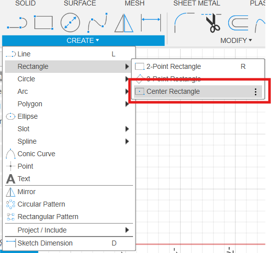
Using Center Rectangle for symmetry.

Step 2: Creating the Solid Base

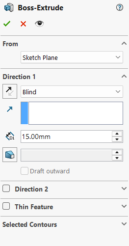
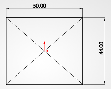
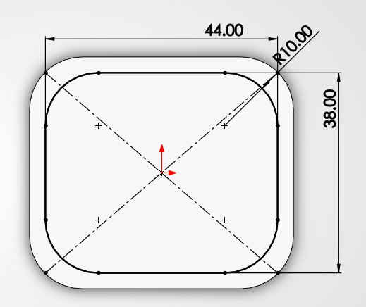
Now we define the size: 60 x 70 mm. Once the sketch is ready, we use the Extrude tool to turn that rectangle into a 3D block. We're going for 18 mm in height to give it enough weight and presence on the desk.

Dimensions

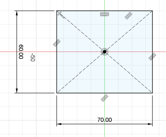
Setting the 60x70mm footprint.

Extrude Tool

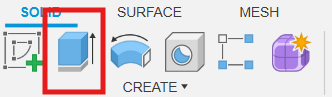
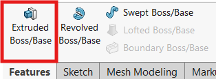
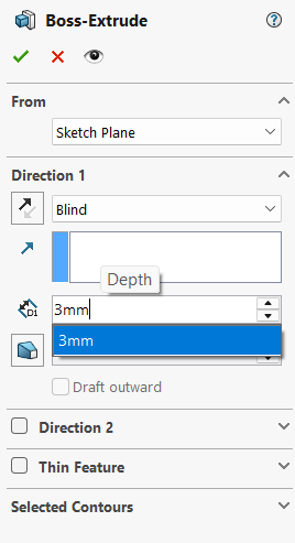
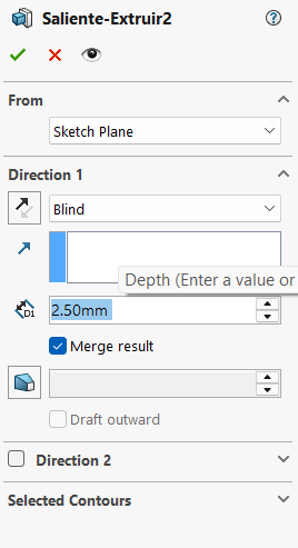
Switching to the Extrude tool (E).

Extrude Menu

Setting the height to 18 mm.

Base Result

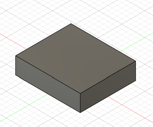
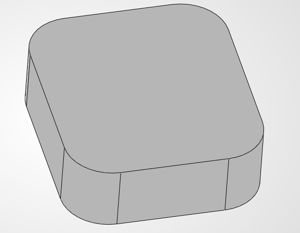
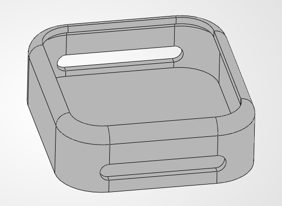
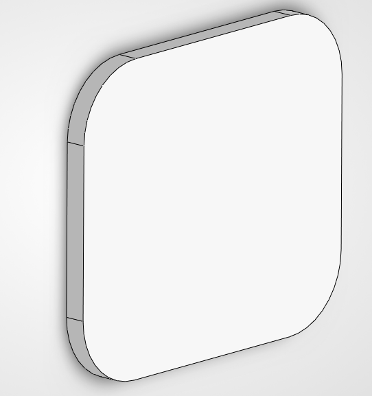
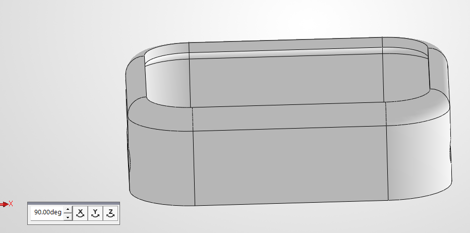
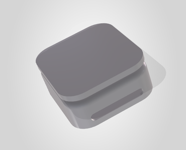
Our first 3D solid base is ready.
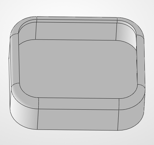
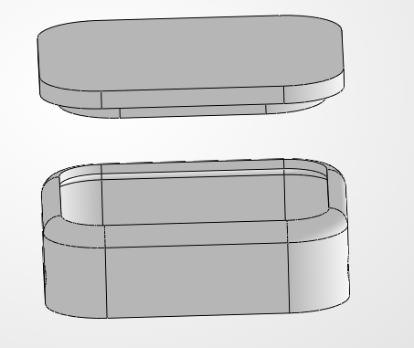
Step 3: The "Nest"

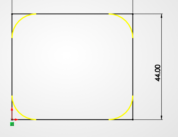
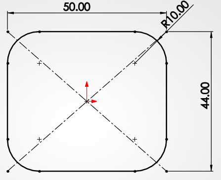
We need a hole where the watch will sit. We'll draw another rectangle (44.4 x 50.4 mm) right on top of our block. To make it easy to use, we'll use a -5° Taper Angle in the cut operation. This creates a "slanted" wall that guides the watch right into the center even if you drop it slightly off-target.

Inner Sketch

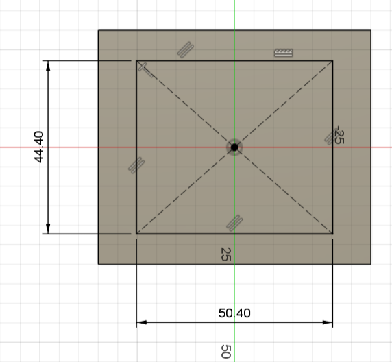
Sketching the cavity with 0.4mm tolerance.

Cut and Taper

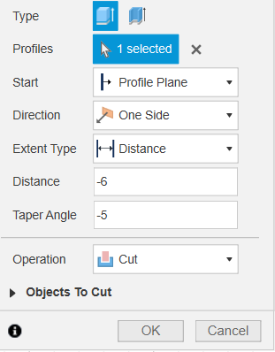
Cutting 6mm deep with a -5° angle.

Nest Result

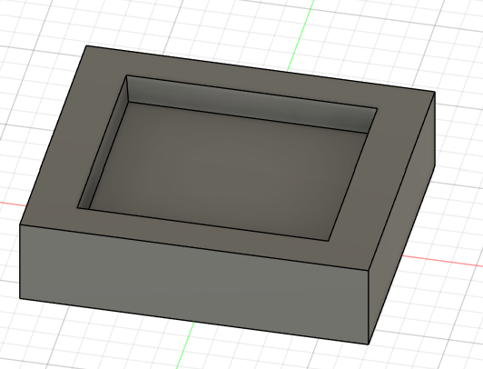
This "funnel" effect is great for accessibility.

Step 4: Preparing for Wireless Charging

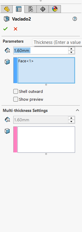
Flip the dock over. We need to get the induction coil as close as possible to the top. We'll draw a 30 mm circle and cut into the bottom. We are leaving a thin 1.2 mm wall to making the energy transfer work.

Circle Tool

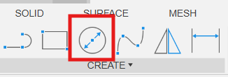
Selecting the Circle tool for the coil.

Circle 30mm

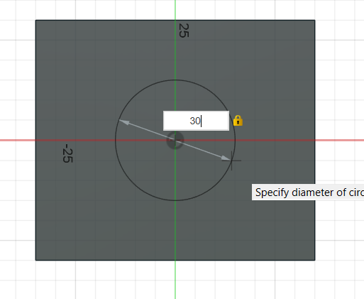
Drawing the 30mm diameter on the bottom face.

Induction Cut

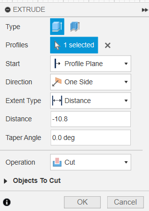
Cutting -10.8mm deep into the base.

Coil Cavity Result

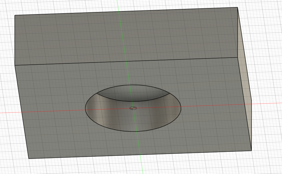
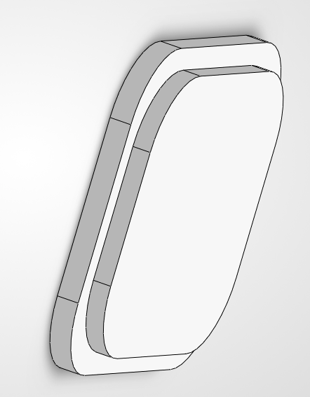
The internal housing is now finished.

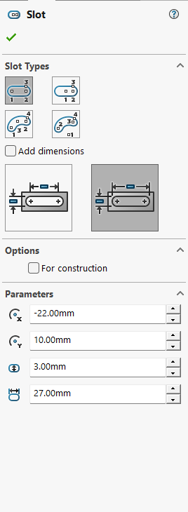
Step 5: Modeling the Cable

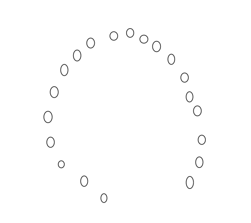
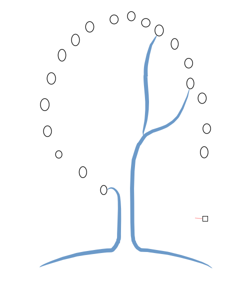
We will use the Fit Point Spline tool. This lets us draw a curvy, natural path. Once we have the "skeleton" of the cable, we use the Pipe tool to give it a 3.5 mm thickness.

Spline Path

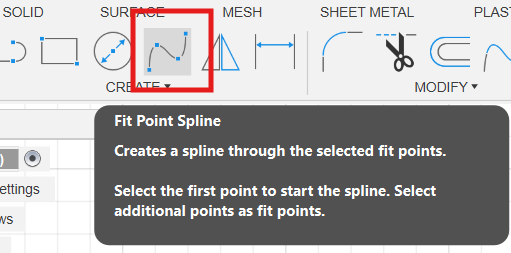
Drawing the wire path with the Spline tool.

Spline Usage

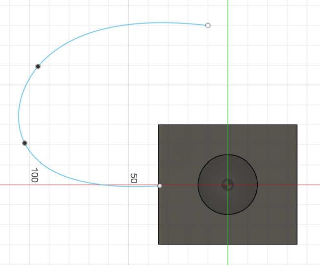
Creating an organic curve for the cable.

Pipe Tool Location

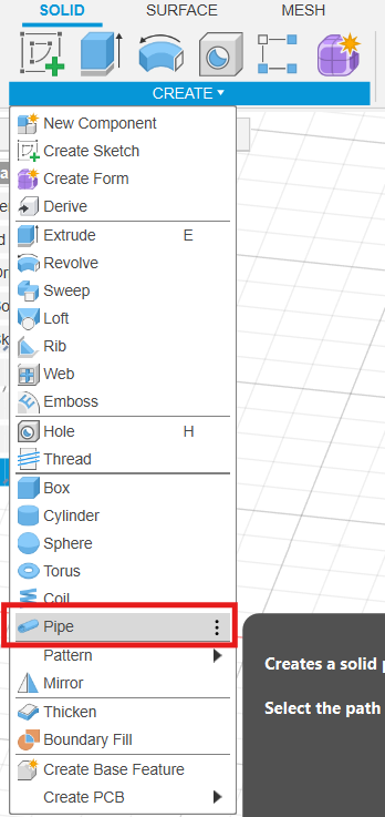
Finding the Pipe tool in the Create menu.

Pipe Settings

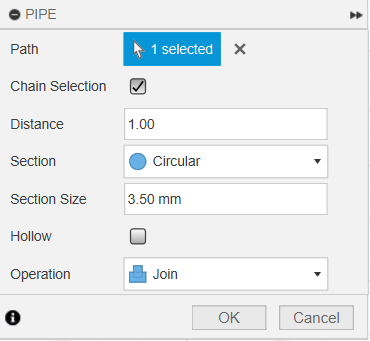
Setting the section size to 3.50 mm.

Cable Result

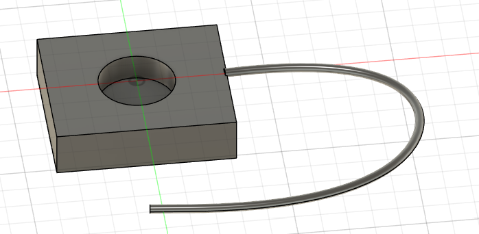
The 3D cable is now attached to the dock.

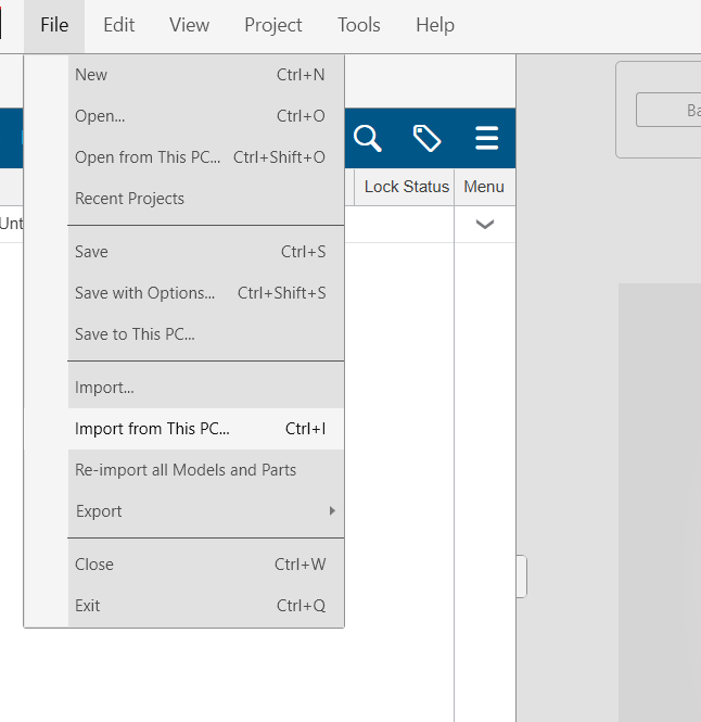
Step 6: USB-A Connector & Final Details

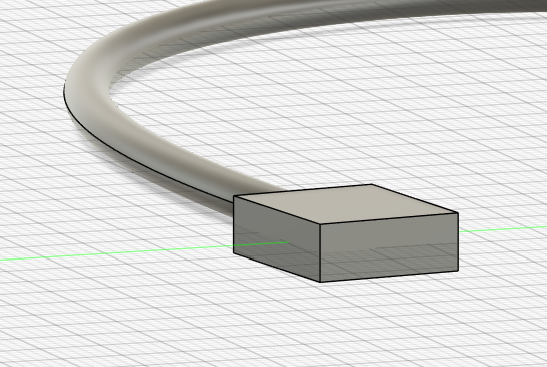
To finish the model, we need the USB plug. 
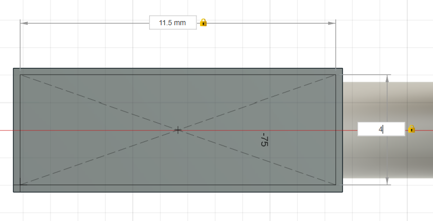
We'll build it in two parts: first the plastic housing (a 4.5 x 12 mm rectangle) and then the metallic tip. By extruding these separately, we get a much more realistic result.

USB Body Sketch

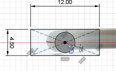
Sketching the USB-A plastic body.

USB Extrude

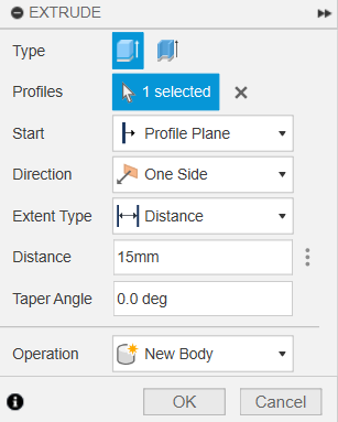
15mm extrusion for the main connector.

USB Result

View of the plastic part of the USB.

USB Tip Sketch

Drawing the metallic connection part.

Tip Extrude

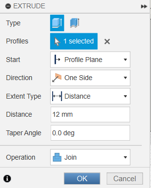
12mm extrusion for the USB port plug.

Final Design

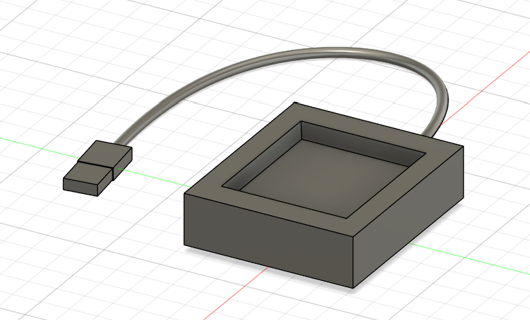
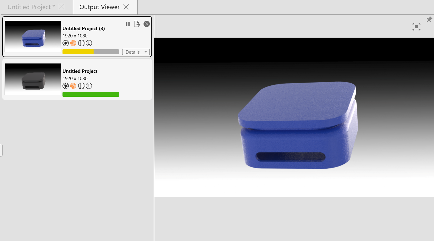
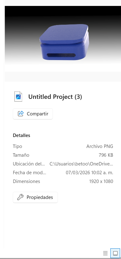
Complete Charging System.

Interactive 3D Preview

You can interact with the final 3D model below.

4

Designing Logo

Step 1: Interface & Organic Shapes

First, familiarize yourself with the Inkscape Menu. We start by selecting the Circle Tool. We create a cluster of circles without worrying about precision, just to define the visual volume of the logo.

Inkscape Menu

Main Menu and interface.

Circle Tool

Selecting the Circle tool (F5).

Organic Cluster

Brainstorming shapes with circles.

Step 2: Drawing the Main Structure

Switch to the Pen Tool (Bézier Curves) to draw the trunk and main branches. We use a circle as a temporary guide to ensure the branches converge naturally. At this stage, the Layers Menu is keeping the guides and details on separate layers makes the workflow much cleaner.

Pen Tool

Using the Pen tool for custom paths.

Drawing Trunk

Drawing the trunk with guides.

Layers Menu

Organizing the design into layers.

Base Result

The initial skeleton of the tree.

Step 3: Refining Curves and Nodes

To move from rigid lines to organic branches, we use the Node Tool. By adjusting the handles, we smooth out every connection. Once all branches are corrected, we can select all paths to see the vector network we've built.

Node Tool

Manipulating nodes for smoothness.

Node Correction

Detail of path smoothing highlighted in the red square.

Refined Tree

Result of all corrected branches.

Selected Vectors

Full view of the tree's vector paths.

Step 4: Branch Coloring & HSL Palette

Using the Fill and Stroke and Stroke Style menus, we apply the HSL colors. The main trunk uses H:210, S:45, L:20, and the secondary branches are set to H:205, S:20, L:65.

Clean Guides

Removing the organic brainstorm circles.

Fill HSL

Applying HSL colors to the branch structure.

Stroke Menu

Adjusting stroke width and style.

Step 5: Symmetrical Nodes, Typography & Final Result

After coloring the branches, we use the Circle tool while holding Ctrl to place perfectly symmetrical synaptic nodes. Following the tree completion, we add the project name using the Text Tool. This creates the balanced look of our finished brand identity.

Symmetric Circles

Placing perfect circles with the Ctrl shortcut.

Pre-final View

The tree structure with its final synaptic nodes.

Text Tool

Adding typography to complete the branding.

Final Result

The Final Logo: The Tree of Synaptic Connections.

Step 6: Exporting to PNG

The final step is to save our vector work as a high-quality image. We go to File > Export to open the sidebar, where we can configure the resolution and area to convert the design into a PNG file.

File Export

Navigating to the File > Export menu.

Export Settings

Configuring export parameters for PNG.

5

How to Compress an Image

Step 1: Open Image in GIMP

The workflow begins by importing your high-resolution image. Navigate to File > Open and select your target image.

File opening workflow

File opening workflow in GIMP.

Step 2: Scale Image

To reduce the file size significantly, we first adjust the physical dimensions. Go to Image > Scale Image. It is essential to choose the right Interpolation (Cubic for quality, Linear for speed) and keep the chain icon active to maintain original proportions.

Interpolation options

Selecting interpolation methods.

Proportion adjustment

Adjusting dimensions with the chain icon active.

Best practice: Always keep the chain icon active to prevent image distortion.

Step 3: Adjust Export Quality

When exporting, the format matters. Use File > Export As. For JPEG, a quality setting between 70-85% offers the best balance. For PNG, use compression level 9 to minimize size without losing pixel data.

Quality control in export

Adjusting the JPEG quality slider before saving.

Step 4: Save and Verify

Finally, save your version with a descriptive filename. Always check the final file size to ensure it meets the project's requirements.

Optimized saving

Reviewing the final file size preview.

6

Video Compression using FFmpeg

FFmpeg is a versatile command-line tool. it doesn't have buttons; it works through precise text instructions.

Step 1: Installation via Winget

First, we need to install the software. Open Git Bash and type the following command. Using winget is the modern way to install tools in Windows because it automatically configures the paths so the computer "recognizes" FFmpeg from any folder.

Installing FFmpeg

Running the winget install command.

Accepting terms

Accepting terms to complete the setup.

Step 2: Navigating to your Work Directory

Before running the compression, the terminal needs to know where your video is. We use the cd (Change Directory) command followed by the path.

For example, cd ~/Documents/video tells the terminal: "Go to my personal folder (~), then to Documents, and finally enter the folder named 'video'". Without this step, FFmpeg won't find your file and will return an error.

Navigation

Navigating to the specific folder before compressing.

Step 3: Executing the Compression

Once inside the correct folder, we paste the compression command. This instruction tells FFmpeg to take the original file, resize it to 480 pixels in height (maintaining the aspect ratio with -1), and apply a high-efficiency codec (x264).

ffmpeg -i Example.mp4 -vf "scale=-1:480" -vcodec libx264 -crf 28 -an Example_final.mp4
Processing

The terminal processing the frames of the video.

Step 4: Final Comparison

After the terminal finishes, you will see two files in your folder. In our test, the weight dropped from a heavy 136 MB to 5.62 MB. Crucially, by checking the file properties, you can see that the duration is identical; no frames were lost, only unnecessary data was removed.

Original size

Original file (136 MB).

Final size

Optimized file (5.62 MB).

Side by side

Visual confirmation of the new file generated.

7

High-Quality Rendering with SOLIDWORKS Visualize

To showcase the wearable casing in a realistic environment, we use SOLIDWORKS Visualize. This tool allows us to apply professional materials and lighting to our 3D models, turning a technical file into a photorealistic presentation.

Step 1: Importing the Geometry

The process begins by starting a new document and importing the 3D model. We select the "Import from this PC" option to locate the specific casing file. Once imported, the geometry appears in the workspace ready for texturing.

New Document Menu

Creating a new project in Visualize.

Import Source

Selecting the local import option.

Imported Model

The wearable casing model loaded in the workspace.

Step 2: Defining the Aesthetic

The Appearances Menu is where we define how the surface interacts with light. After testing various finishes, we decided on a Blue Soft Touch appearance for the final version, as it provides a professional, matte feel suitable for a wearable device.

Appearances Menu

Browsing the materials library.

Applied Appearance

Initial material tests on the casing.

Trial Renders

Experimenting with different surface reflections.

Final Material

Final selection: Blue Soft Touch finish.

Step 3: Render Settings

With the materials set, we open the Render Wizard. We configure the output as an "Image" and select the PNG format to maintain a clean background. These settings ensure the best balance between rendering time and image quality.

Render Wizard

Opening the Render Wizard tool.

Image Option

Choosing Image output from the wizard menu.

PNG Format

Setting the export format to PNG.

Step 4: Final Processing

Once the "Render" option is selected, the software begins calculating the light paths and reflections. After the processing bar completes, we obtain the final high-resolution file ready for documentation.

Render Start

Executing the render operation.

Processing Log

Visualize computing the final image frames.

Final Result

The resulting PNG render of the casing.

8

Weekly Reflection & Conclusion

"The perfect tool does not exist; only the right workflow does. Attempting to solve every challenge with a single program is an impossible task. This week, I learned to navigate between different digital environments, leveraging the unique strengths of each to bring my project to life."

This week was a journey through the diverse "toolbelt" required for SafePath. By exploring 3D, 2D, and optimization software, I realized that the value of a developer lies in knowing which tool to pick for a specific problem rather than mastering just one.

  • 3D Foundations: Used SolidWorks and Fusion 360 for technical precision in the induction dock and casing design.
  • Creative Identity: Leveraged Inkscape to develop the visual branding and logo for the project.
  • Photorealistic Presentation: Utilized SOLIDWORKS Visualize to transform technical 3D models into lifelike previews, applying professional "Blue Soft Touch" finishes to the wearable casing.
  • Web Optimization: Mastered GIMP and FFmpeg to ensure this documentation remains high-quality yet lightweight for the web.