My Final Project example
These are my sketches of the final project, and if they are different ideas, since I was and am in a position to choose.

sketches
In 3 of these 4 sketches I would like to implement a flexible structure that works as a support, so in the crab sketches the cobra and the scorpion have some part with this.
Cobra/or snake
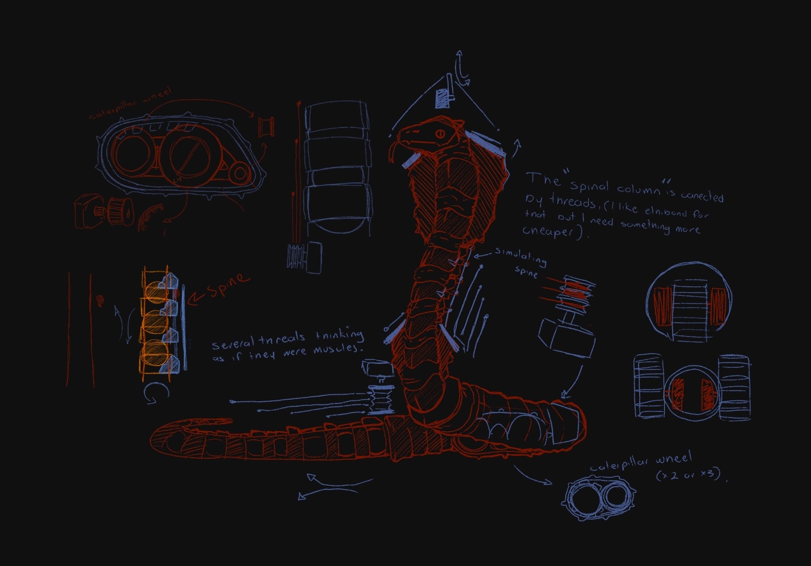
With this structure I want it to be assimilated to the spine, so it is made up of "vertebrae" connected one by one with threads that will be guided by the vertebrae to be pulled on a reel by a motor. Between vertebra and vertebra I will put either a ball or something flexible like a silicone mattress. But why do I add this? Well, something I want to add to this animatronic is the characteristic lift of the animal, for this I must put the structure suggested above, in addition to that to give a forward movement I want to add internally a tracked wheels (the one that war tanks have) exactly in the middle part to be able to make that part wider and put the servomotors for the stability structure.Crab
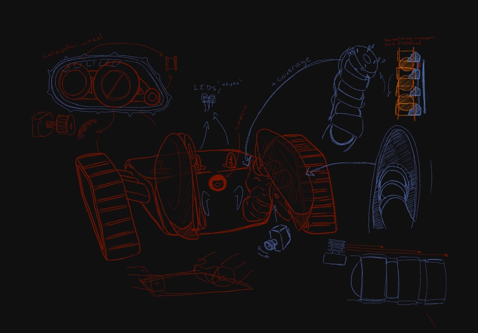
The caterpillar wheels are responsible for moving the crab and carrying its structure, as they are like its legs. At the joints of the legs I would like to add some suspension for the body. And what I would focus on the most would be the "arms" and their pincers. These arms would be made up of a structure of stability simulating the spine. Well, I want the attachment of his body to his grippers to be flexible and even stretchable.Scorpion
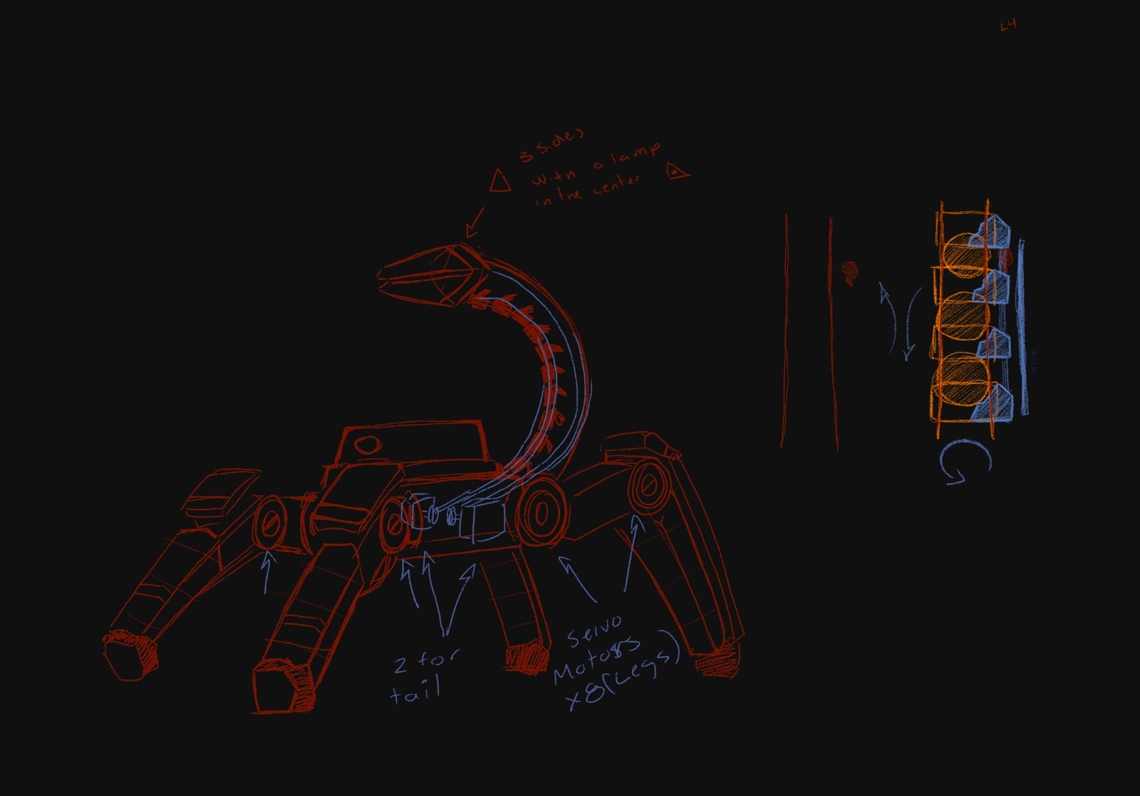
Similar to the crab, here he would implement the crab's arm in the scorpion's tail, adding a pincer at the end to grab objects. In this I would like to add how the vertebrae of the spine are joined in the structure of stability that would be the tail of the scorpion. This same tail will be pulled by "threads" I thought of the ethibond 5 surgical thread but it is too expensive, the box of this one costs about 550 dollars, so I am still looking for a thread that can withstand states of stress.bone screws
This sketch was more dedicated to the problem that arises from broken bones, many times it is optimal to use a bone screw that is custom-made, but for time, money and precision, metal screws are usually placed.
I was talking to Dr. Colmenares, a traumatologist and surgeon at the Angeles Hospital Puebla and an expert in the spine. In addition to being very scarce, these calaveric screws are very difficult to model with a hand drill with a diamond tip. So I suggested this sketch.
It is basically a combination of a lathe (because of the grip mode and how it rotates) and a CNC (programming the arm to drill at specific points thus modeling the part).
Problems
Project Schedule
Here's a complete list of tasks for the design, electronics, assembly, and testing phases:
| Week | Task | Status |
|---|---|---|
| Week 1 (Apr 21 – Apr 27) |
Define robot architecture Sketch arms, eyes, caterpillar tracks Start PCB designs: main board, motors, sensors, camera, WebSocket |
Completed |
| Week 2 (Apr 28 – May 4) |
Finish PCB schematics/layouts Full 3D design of robot (chassis, wheels, arms, eyes) Choose materials for molds and prints |
Completed |
| Week 3 (May 5 – May 11) |
PCB fabrication (all boards) 3D print prototypes: wheels, arms, eyes Plan electronic tests |
In Progress |
| Week 4 (May 12 – May 18) |
PCB testing Integrate motors and tracks Start firmware development for each board |
In progress |
| Week 5 (May 19 – May 25) |
Assemble electronics on chassis Mechanical test: movement and arms Design molds for external parts |
Pending |
| Week 6 (May 26 – Jun 1) |
Develop WebSocket interface Test server-client communication Finalize resistance and wiring layout |
In progress |
| Week 7 (Jun 2 – Jun 9) |
Final tests: sensors, motors, camera Finish assembly Submit complete project: Code, 3D files, PCB files, documentation Video and image assets |
Pending |