7. Computer-Controlled Machining
This week's topic is using a CNC, especially a milling machine, so there are lots of unique ideas, ranging from a box to a kayak (which I saw on a fantastic website of the Fab Academy!). The computer-aided numerical control technique is a subtractive manufacturing method that involves the removal of material from a workpiece using a variety of rotating tools.
group AssignmentThe computer-assisted numerical control technique is a subtractive manufacturing method that involves removing material from a workpiece using a variety of rotary tools. The CNC cutter cuts accurate forms from metal, plastic, wood, and composite materials using preprogrammed processes.
STEPS!
| Part Design: | My design will only require two-dimensional toolpaths, but we must take into account the geometry of our components while designing a CAD model in our preferred program. |
| CAM software: | Once our model is complete, we must translate it into instructions for Computer Aided Manufacturing (CAM), which specify how the machine will move and cut the material. |
| CNC machine setup: | involves setting up a point of origin for the carving operation, securing our material on the machine bed, and installing the appropriate tool. |
| Program Execution: | After reading the G-code, the CNC controller moves the cutting tool along the preprogrammed routes. |
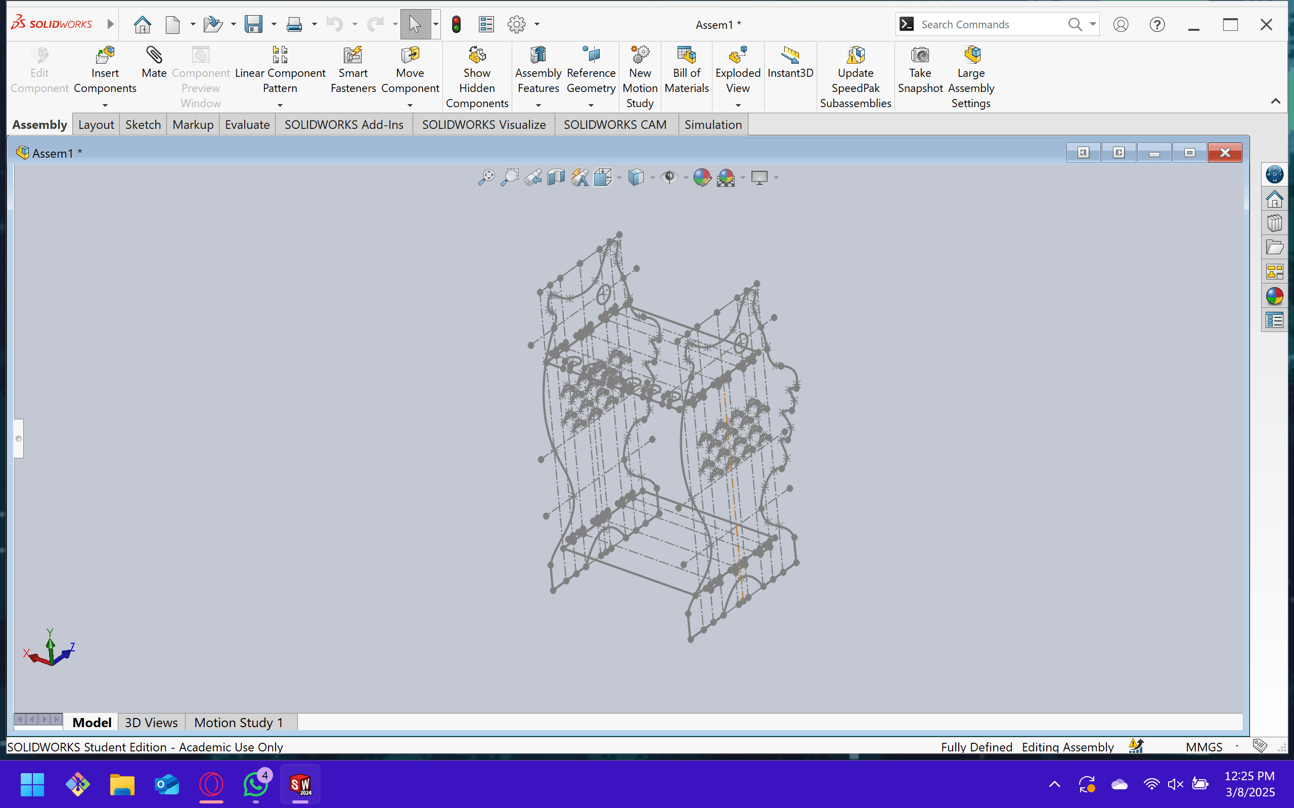
So I set out to design it in Solidworks!
To choose furniture that fit my home, was useful, and had a beautiful design, I spent a lot of time discussing my plans internally. Just build a piece of furniture, right?
I mean, why not take advantage of the opportunity? I made the decision to utilize this week to create a piece of furniture but not just any furniture for my father's birthday! It will be transformed into a sea bass-shaped fishing rod holder! Although he has never had a suitable place to keep and show off his fishing rods, he is an avid fisherman and his birthday is March 13.
I mean, why not take advantage of the opportunity?
I made the decision to take advantage of this week to create a piece of furniture, but not just any furniture, but one for my father's birthday! It will transform into a bass-shaped fishing rod holder! Although he has never had a proper place to store and display his fishing rods, he is an avid fisherman and his birthday is March 13.
So I set out to design it in Solidworks!
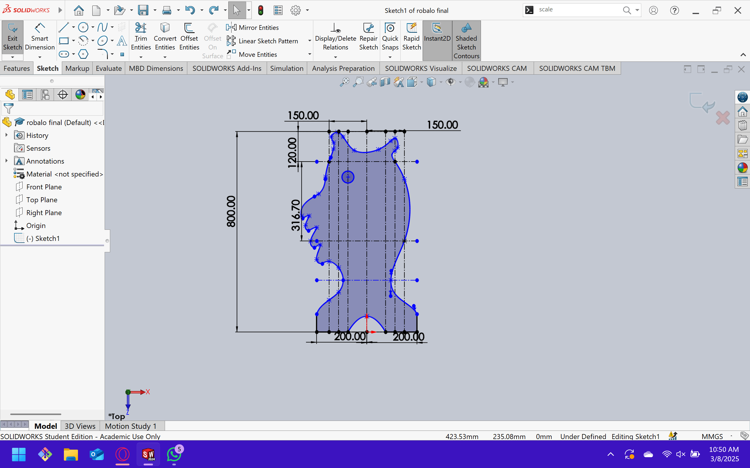
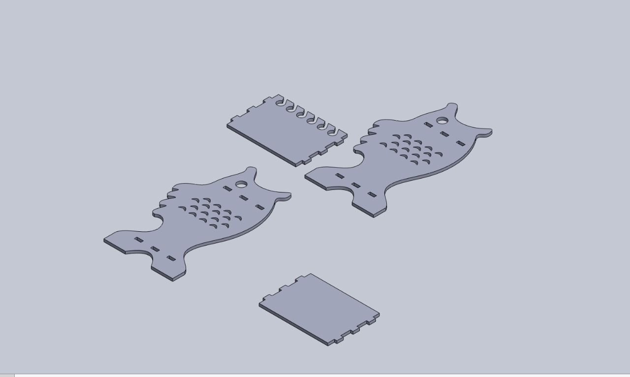
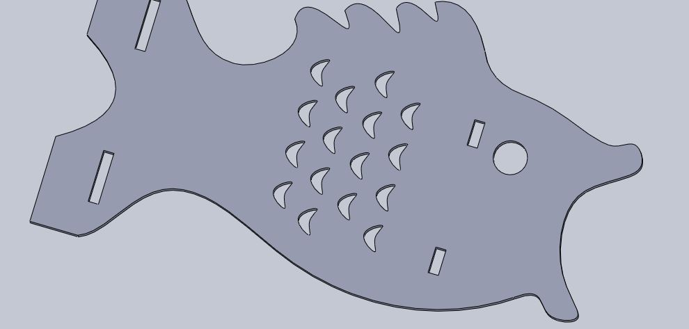
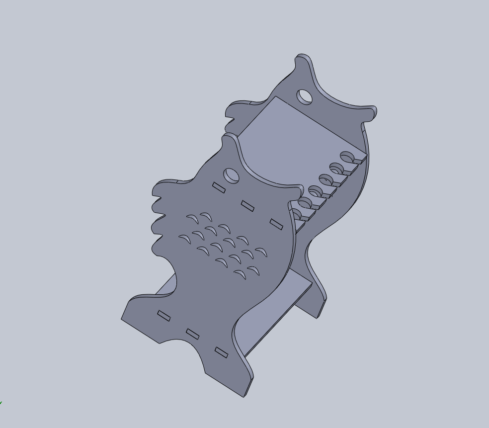
I chose to design my piece initially in SolidWorks. It is crucial to be able to verify the size of my design and my elements, in addition to grouping them in an assembly to have an advance vision of the final product that would be the sea bass. First, I designed a fish, although it was a bit difficult, since with SolidWorks vectors it was difficult to assign measurements and references to them.
Later, they will make scales with the patterning tool, creating an eye-shaped hole and two rectangles for the eyelashes that will be placed on the shelves.
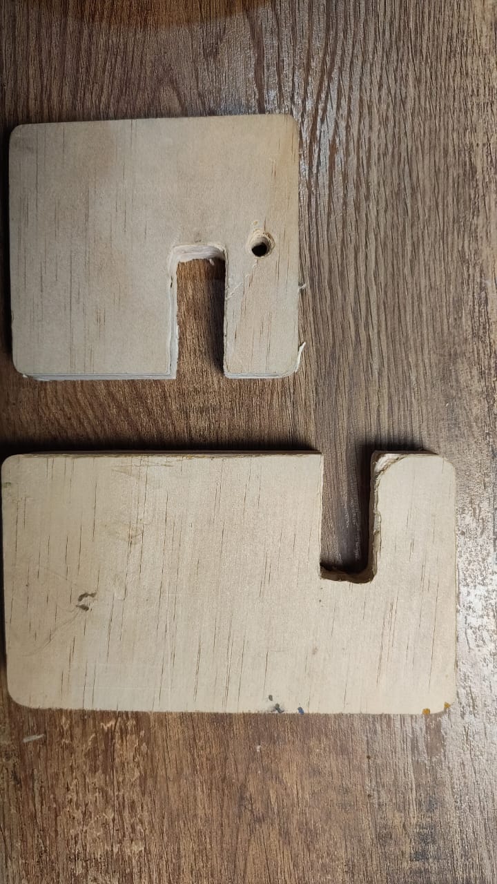
Actually, at first glance I duplicated the file and quickly made identical shelves, except for the second one that includes holes to store the fishing rods. It may be quite simple, essentially a box, but what really interests me about using this machine is that it can create perfect curves and shapes, not like a tabletop router. It has measurements, it can change from inorganic to organic forms as if without effort. This really excited me and I'm considering making some other furniture, or improving the design and incorporating doors and drawers into it.
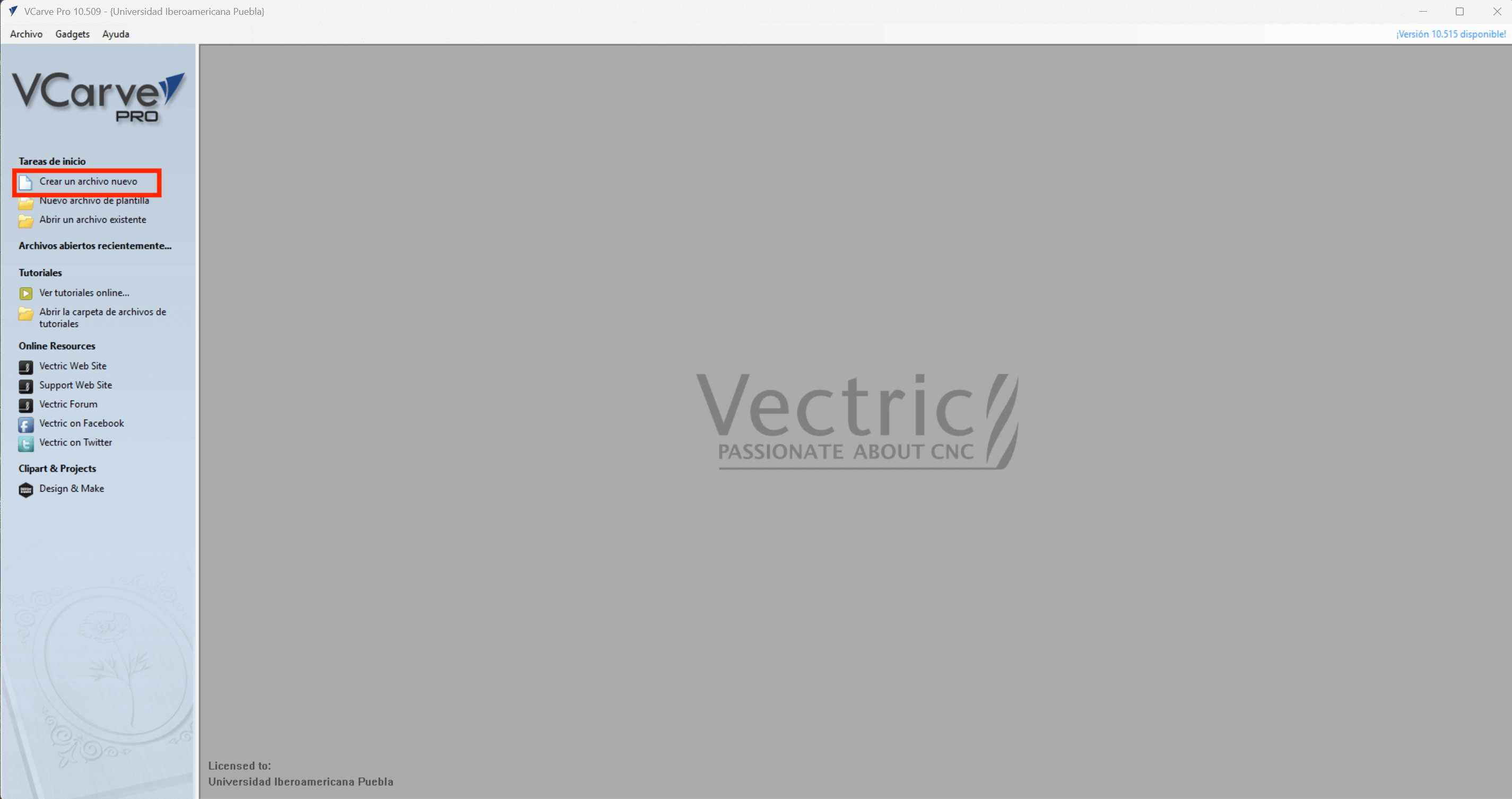
CAM SOFTWARE – VCARVE
Our DXF file will be converted into the machine instructions we need to use the CAM Software. A range of CAM software is available for us to utilize; I'll be utilizing VCarve, a program created by Vectric that is frequently used for CNC routing, engraving, and sign creation.
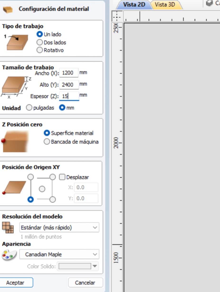
We will create a new project, where it will ask us to enter certain parameters such as the measurements of your material (Now we will have to decide what size will be the surface of the material in my case I will use 1200 mm X 2400 mm X 15mm) or the origin of its axes.
First what we will import will be our dxf to be able to start working (in my case the fish/snook furniture), it is recommended that in your dxf it does not contain the construction lines, since they will be transferred to the vcarve but it does not matter at all since it can be edited in the same program but it will put it as separate lines and not as a single guide.
In the same way that we can remove our build lines we will remove the "watermark" from solidworks. Then we will have to select vector by vector and make a mersh between them so that only one remains.
Now the Femur / T-bones!

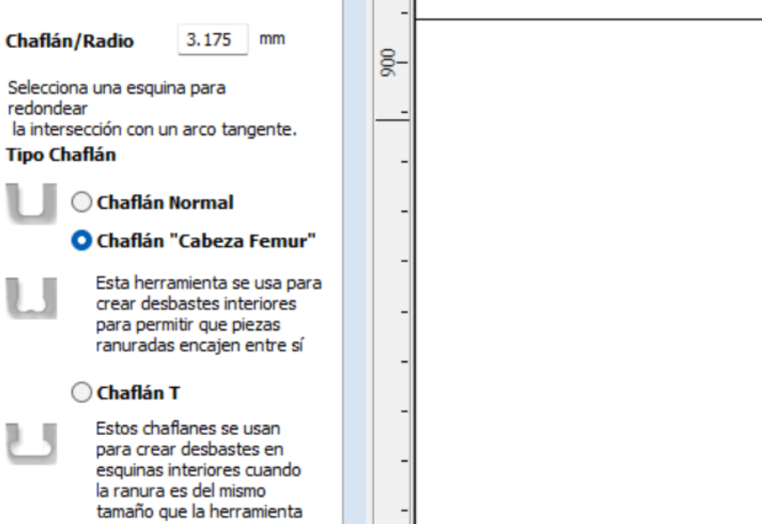
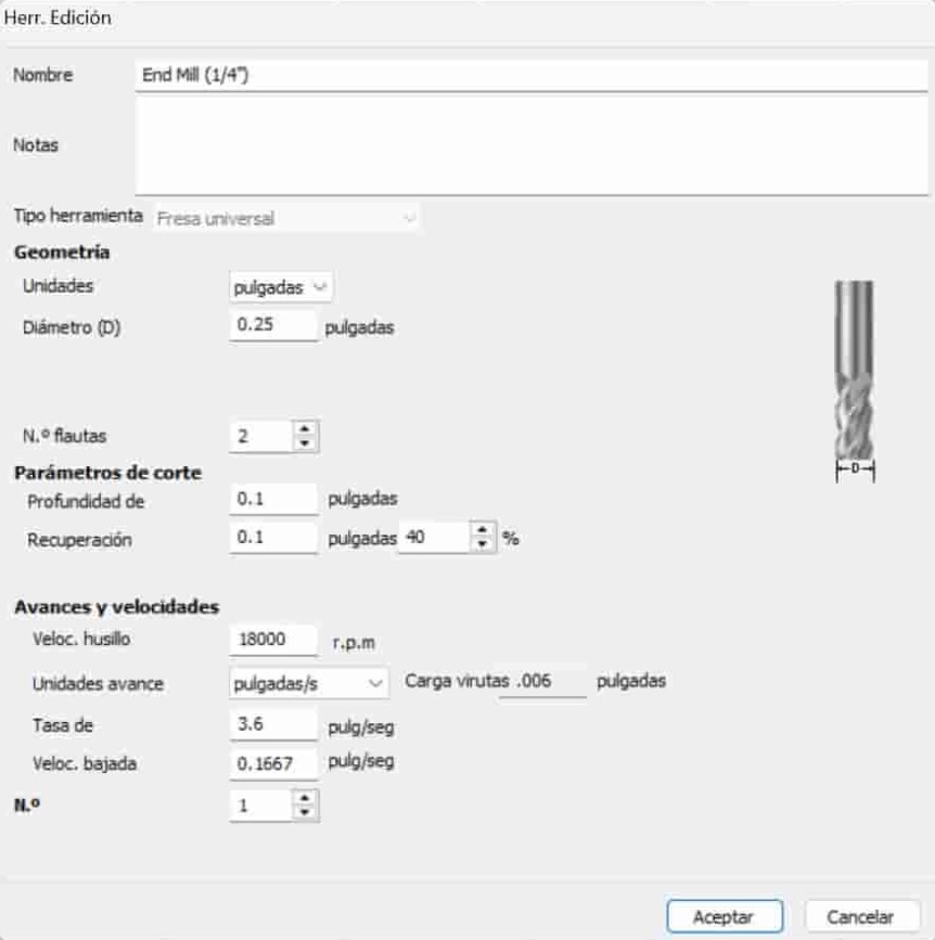
After consulting the aforementioned, we proceed with the profiling tool. The first step is to choose the cut's depth; the initial point would be the origin, and the final depth would depend on the material's warping, as we need it to be greater than the material's thickness to guarantee the cut. Selecting the tool is the next step, so we pick edit to use the previously mentioned information to adjust the tool's parameters. Following tool selection, vector machining proceeds, with three possibilities displayed:
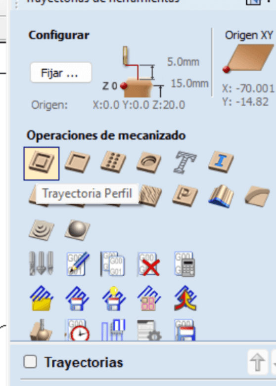
Selecting the components that need this kind of machining is crucial when machining vectors. Internal incisions should be made first, followed by exterior ones.
the tool configuration
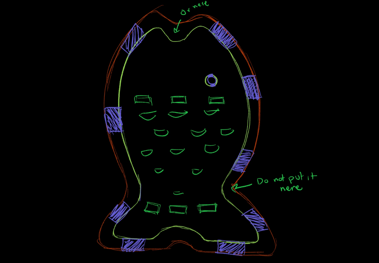
Tabs!
Adding tabs is the next step, it's crucial to avoid making them too thick (which prevents them from breaking) or too thin (which might cause them to break during machining). After placing the tabs, we click Edit Tabs, which opens a new window where we enter the amount of tabs. These tabs will be displayed in the design that we have chosen. If a tab is not in its proper location, we may delete it with a single click and then reposition it with another click.
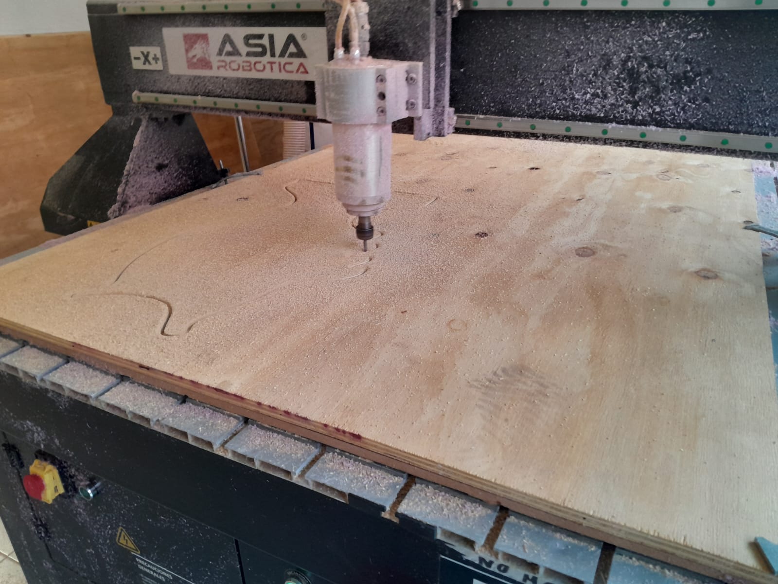
into the router
First of all, we must have our safety equipment on (boots, gown and glasses, that depends on whether you are nearsighted or unresponsive, whether you wear glasses in your daily life or require protection).
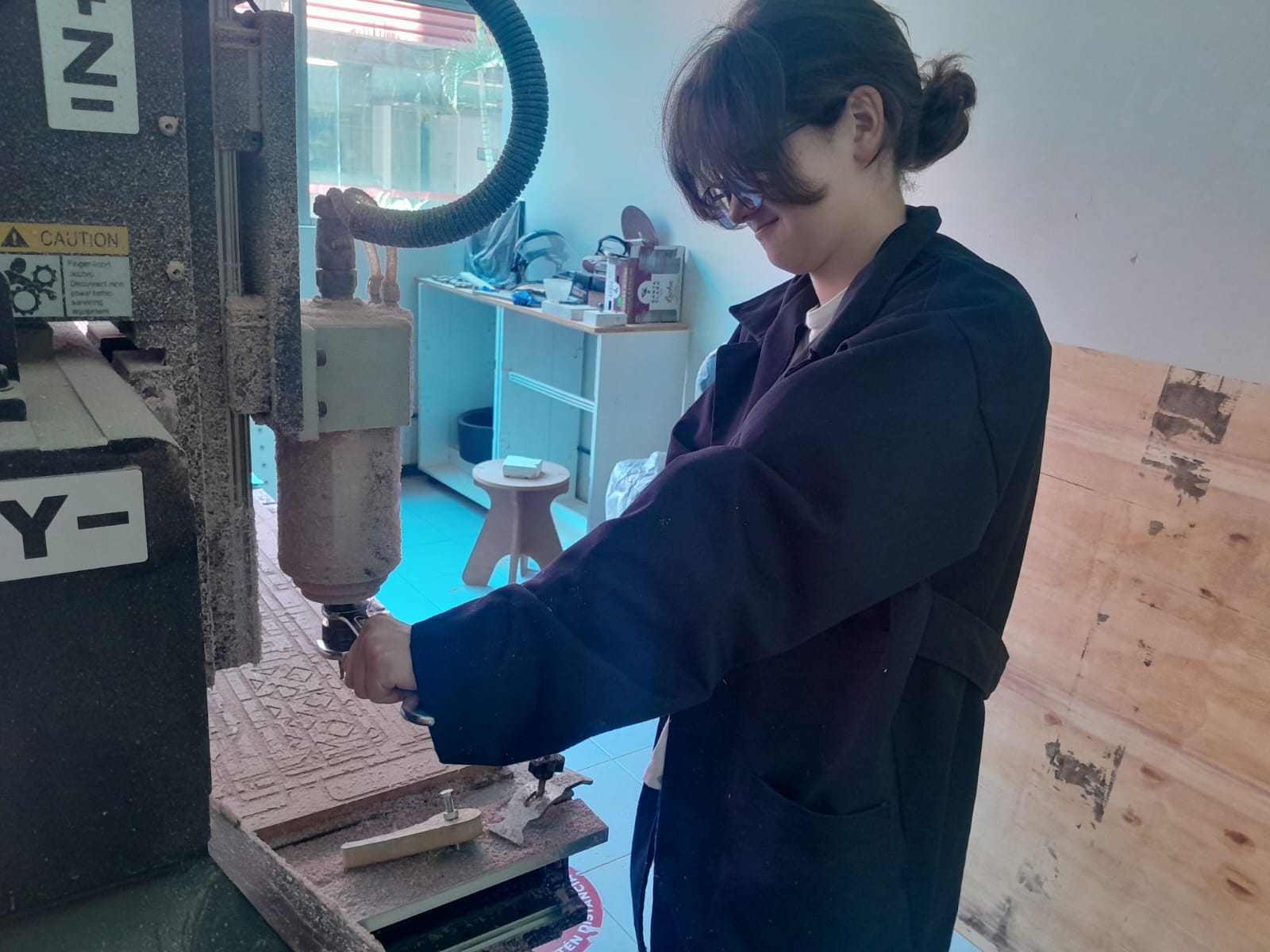
Now we must change the grinding wheel! With two keys of the indicated size we will hold the handle for the drill and the rotating base and we will pull against the clock little by little since it is very prone to the drill bit falling and breaking, I used exactly .25 inch drill bits.
commands
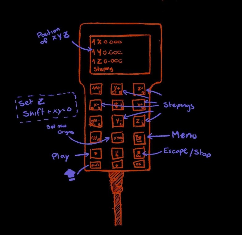
| Function | Control Description |
|---|---|
| Manual Axis Movement (Jog Mode) | Use arrow keys to move along X, Y, Z. Hold "Shift" for faster movement. |
| Set Zero Point | "XY→0" sets zero for X and Y axes. "Z→0" sets zero for Z axis. |
| Load Files from USB | MENU → ADVANCE PRO → FILE MAINTENANCE → COPY. Select file from USB and copy to DSP memory. |
| Run G-code File | Press "RUN" → Select "INNER" → Choose file → Press "OK" to start execution. |
| Spindle Control | "Spindle ON/OFF" toggles spindle. Adjust speed using "Spindle Speed" option. |
| Pause and Resume | "Pause" temporarily stops operation. "Continue" resumes the job. |
| Return to Home | "HOME" returns the tool to its predefined origin point. |
the material
but it's not just adjusting the nut, noooo it's adjusting the wood and fixing it! That's why we have those little metal things to cut, we must ensure that the cut does not interfere with its passage or disturb the drill bit and the handle.
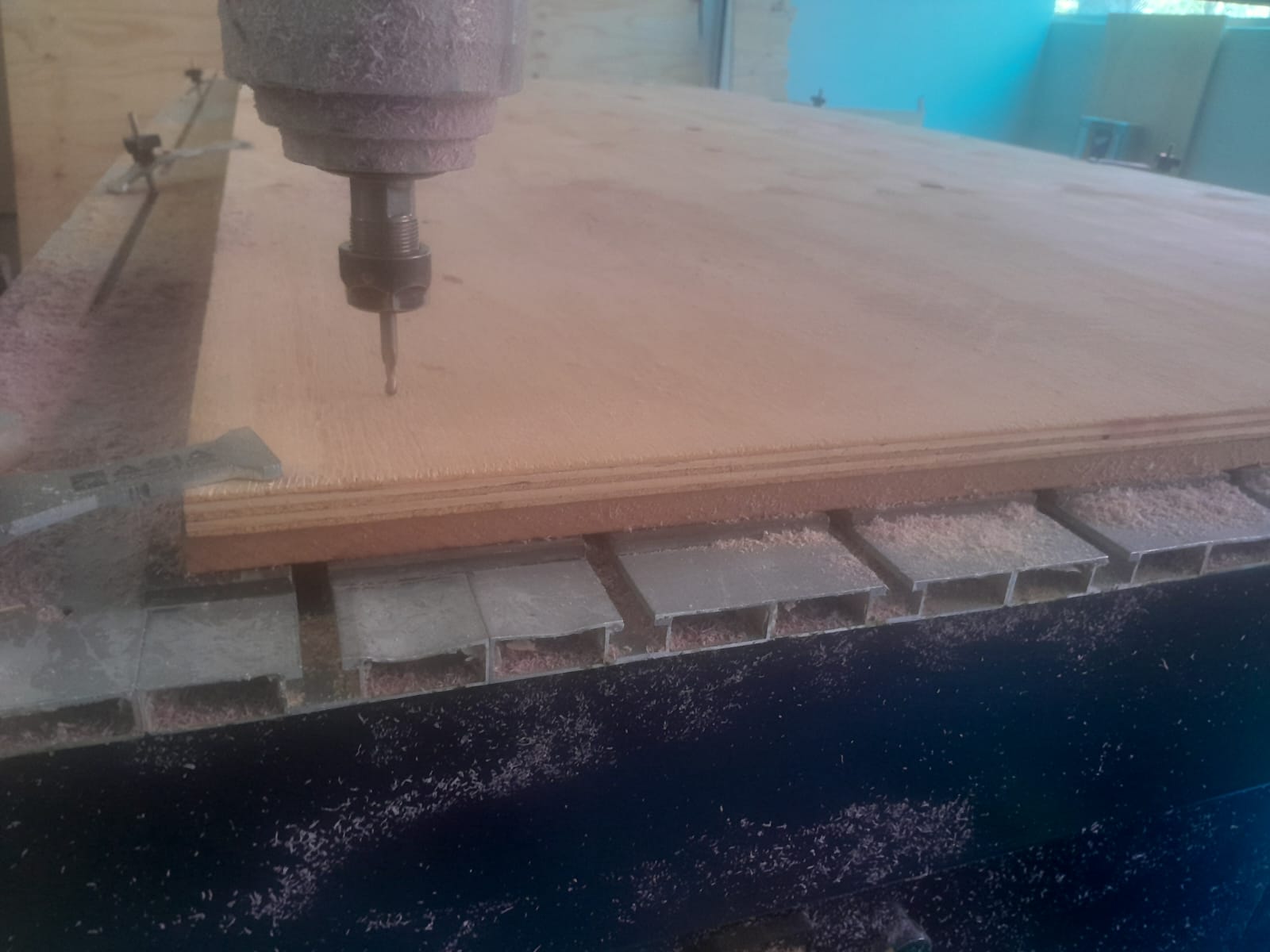
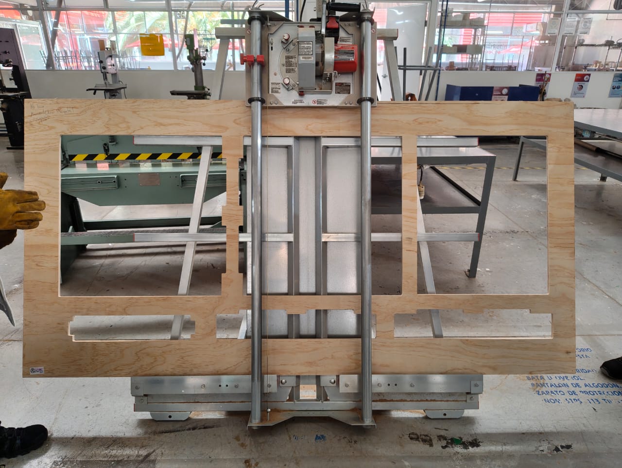
Now if everything is ready we can start cutting!
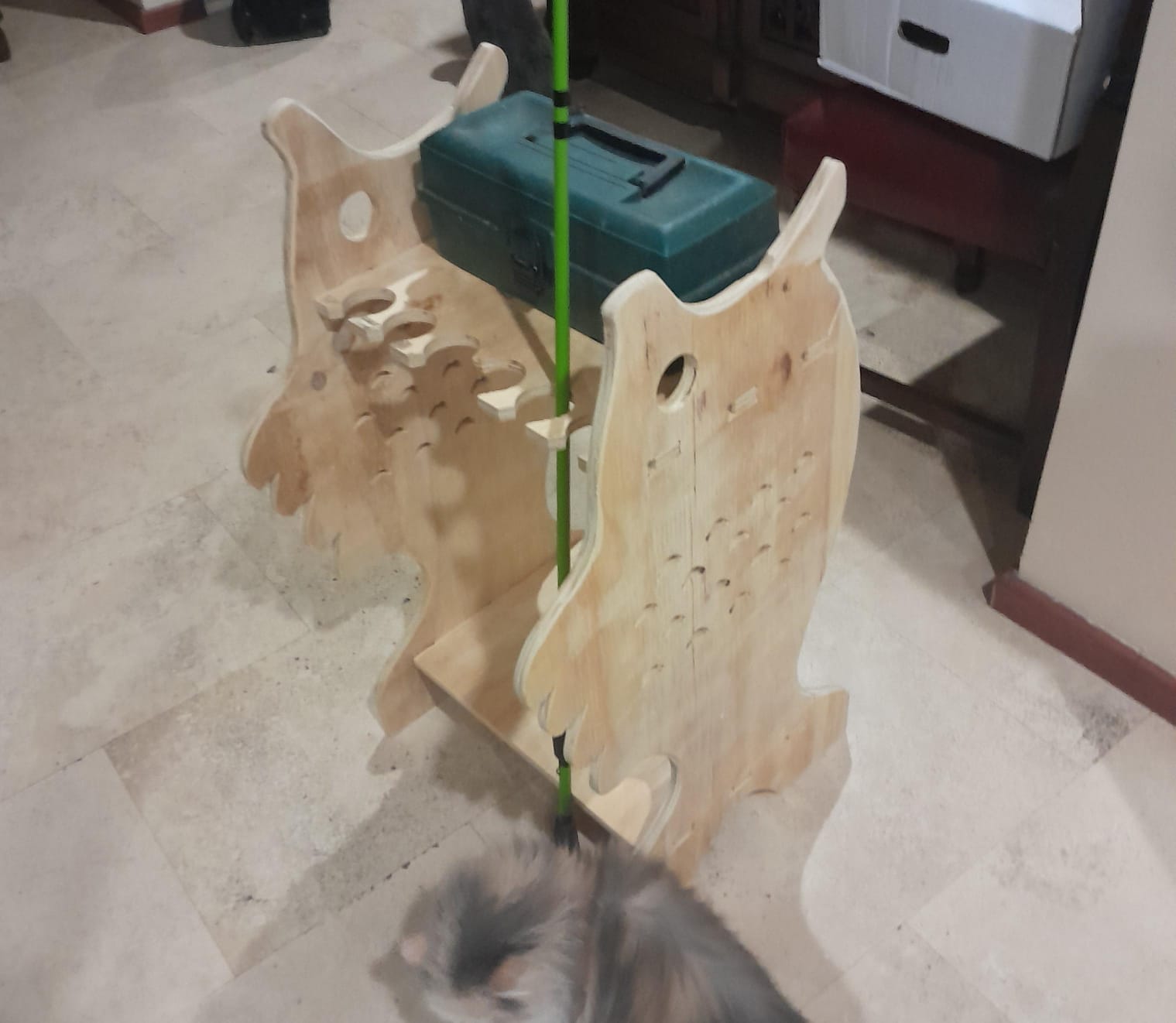
ensamble! (VOLTRON!)
The only thing missing would be to assemble everything, since as soon as it is cut I sanded it 30 minutes before assembling it, remember that you must use a rubber hammer to avoid damaging the wood, and it would be ready this week!
ALSO HERE'S ANOTHER THING!
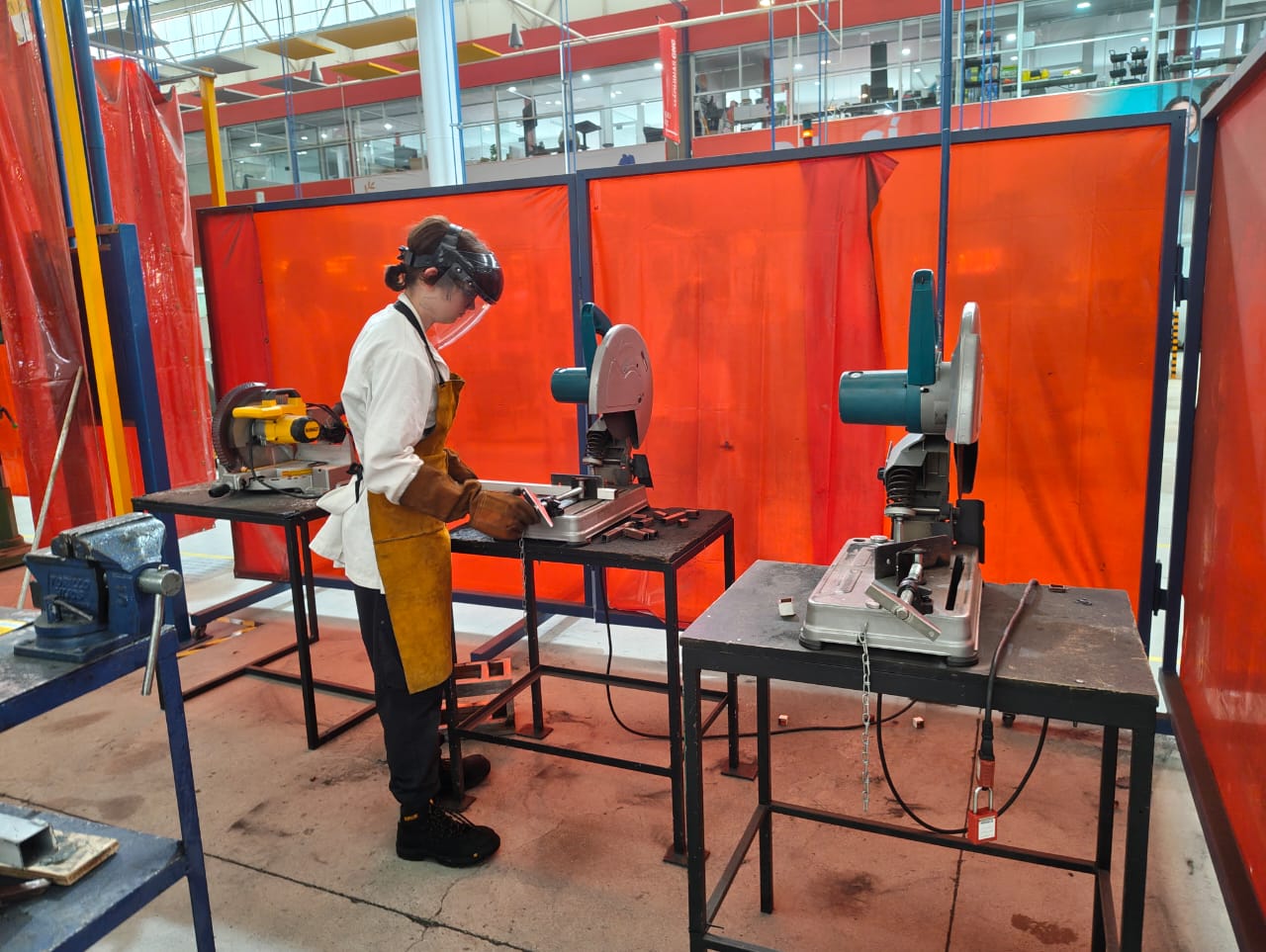
In addition to making cuts with the CNC router, I’ll include my “machinery” week assignment from the Engineering Projects I course; I’m linking them here because I see it as the process that the CNC router could perform but without numerical control, using various tools such as the circular saw and the milling machine. Aside from this, I learned the basic use of some metal-cutting and welding tools.
| Machine | Function | Process | Safety |
|---|---|---|---|
| Metal Saw | Cutting metal sheets, bars or profiles. | The workpiece is clamped and cut using a blade or abrasive disc designed for metal. Pressure is applied steadily until the cut is complete. | Wear eye and ear protection, secure the workpiece, use the correct blade/disc. |
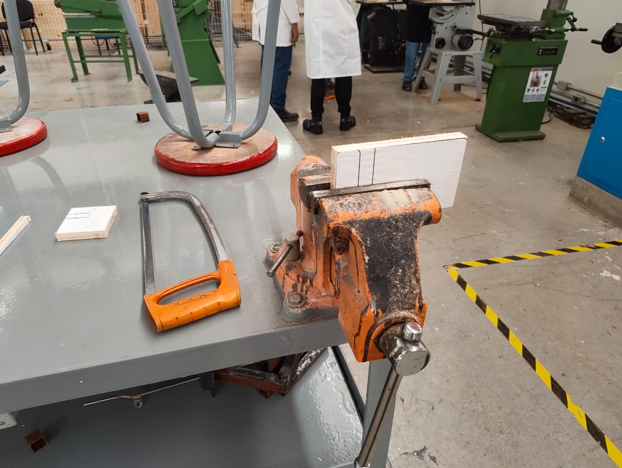
| Hand Hacksaw | Manual cutting of small metal bars, pipes or profiles. | The blade moves back and forth by hand to cut through the material. Pressure is applied on the forward stroke, while the return stroke is lighter. | Wear goggles, keep both hands on the saw, use a vise to hold the workpiece. |
| Milling Machine | Shaping parts by removing material. | The part is fixed to the table or vise, and a rotating cutter removes material layer by layer to form slots, planes or profiles. | Wear goggles, avoid loose clothing, secure workpiece with vise. |
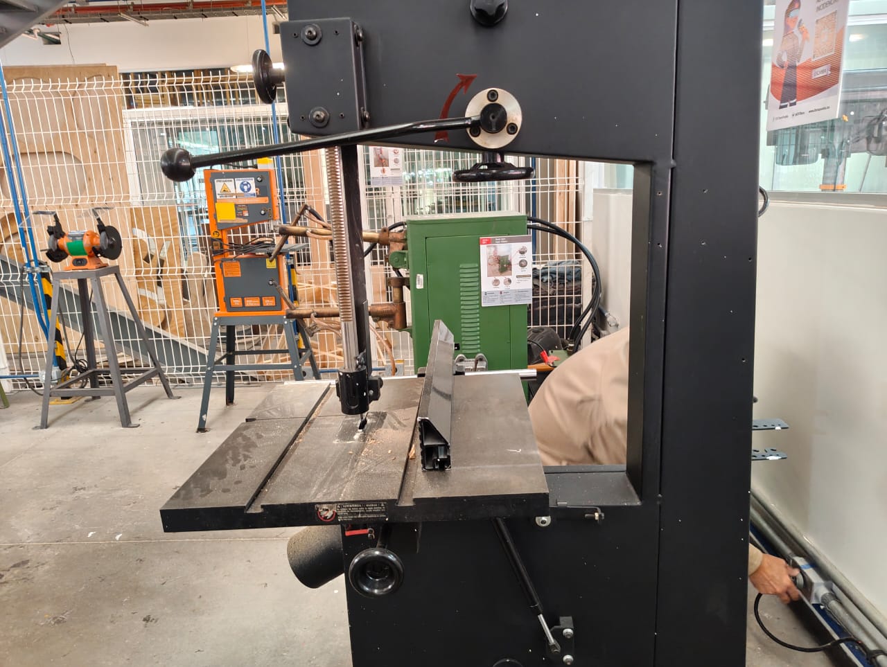
| Straight Saw (Power Saw) | Performing straight cuts on wood, metal or plastic depending on the blade. | The machine drives a straight blade up and down (or in linear motion) while the operator guides the workpiece to achieve a straight cut. | Use eye protection, keep hands away from blade, unplug before blade changes. |
results
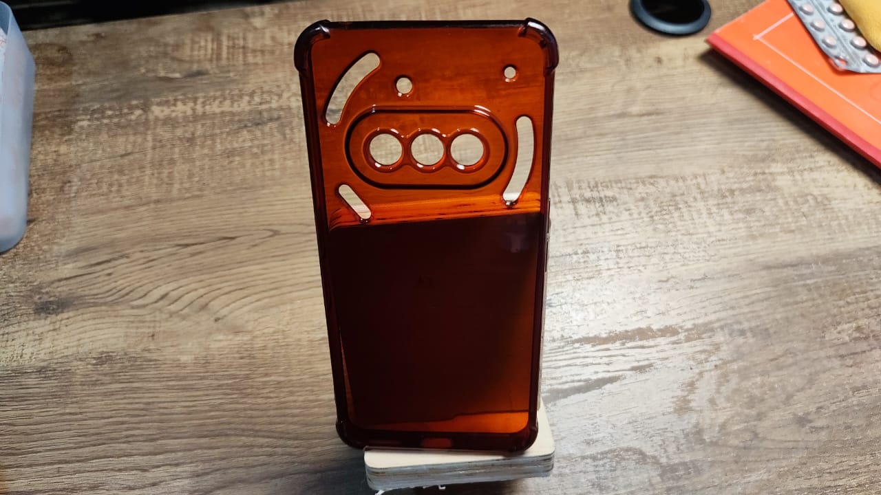
after some procedures this is how it turned out.