  ████████       █████████                                                 █████                                    █████████                       █████                       ████  ████               █████      █████████              █████     █████     ███
 ███░░░░███     ███░░░░░███                                               ░░███                                    ███░░░░░███                     ░░███                       ░░███ ░░███              ░░███      ███░░░░░███            ░░███     ░░███     ░░░
░░░    ░███    ███     ░░░   ██████  █████████████   ████████  █████ ████ ███████    ██████  ████████             ███     ░░░   ██████  ████████   ███████   ████████   ██████  ░███  ░███   ██████   ███████     ███     ░░░  █████ ████ ███████   ███████   ████  ████████    ███████
   ██████░    ░███          ███░░███░░███░░███░░███ ░░███░░███░░███ ░███ ░░░███░    ███░░███░░███░░███ ██████████░███          ███░░███░░███░░███ ░░░███░   ░░███░░███ ███░░███ ░███  ░███  ███░░███ ███░░███    ░███         ░░███ ░███ ░░░███░   ░░░███░   ░░███ ░░███░░███  ███░░███
  ░░░░░░███   ░███         ░███ ░███ ░███ ░███ ░███  ░███ ░███ ░███ ░███   ░███    ░███████  ░███ ░░░ ░░░░░░░░░░ ░███         ░███ ░███ ░███ ░███   ░███     ░███ ░░░ ░███ ░███ ░███  ░███ ░███████ ░███ ░███    ░███          ░███ ░███   ░███      ░███     ░███  ░███ ░███ ░███ ░███
 ███   ░███   ░░███     ███░███ ░███ ░███ ░███ ░███  ░███ ░███ ░███ ░███   ░███ ███░███░░░   ░███                ░░███     ███░███ ░███ ░███ ░███   ░███ ███ ░███     ░███ ░███ ░███  ░███ ░███░░░  ░███ ░███    ░░███     ███ ░███ ░███   ░███ ███  ░███ ███ ░███  ░███ ░███ ░███ ░███
░░████████  ██ ░░█████████ ░░██████  █████░███ █████ ░███████  ░░████████  ░░█████ ░░██████  █████                ░░█████████ ░░██████  ████ █████  ░░█████  █████    ░░██████  █████ █████░░██████ ░░████████    ░░█████████  ░░████████  ░░█████   ░░█████  █████ ████ █████░░███████
 ░░░░░░░░  ░░   ░░░░░░░░░   ░░░░░░  ░░░░░ ░░░ ░░░░░  ░███░░░    ░░░░░░░░    ░░░░░   ░░░░░░  ░░░░░                  ░░░░░░░░░   ░░░░░░  ░░░░ ░░░░░    ░░░░░  ░░░░░      ░░░░░░  ░░░░░ ░░░░░  ░░░░░░   ░░░░░░░░      ░░░░░░░░░    ░░░░░░░░    ░░░░░     ░░░░░  ░░░░░ ░░░░ ░░░░░  ░░░░░███
                                                     ░███                                                                                                                                                                                                                      ███ ░███
                                                     █████                                                                                                                                                                                                                    ░░██████
                                                    ░░░░░                                                                                                                                                                                                                      ░░░░░░
Plan
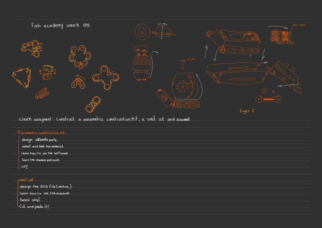
task: Design, lasercut, and document a parametric construction kit, accounting for the lasercutter kerf, which can be assembled in multiple ways. Cut something on the vinyl cutter
Grupal assignments
In this phase of the Fab Academy, I learned to use computer-controlled cutting, in particular, I used CAM-five brand laser cutters. These machines use a CO2 laser, which makes it easier to perform precise cuts in a variety of materials (eliminating kerf, laser thickness, and power). These machines have astonishing accuracy, with a resolution of up to 4000 DPI and the ability to cut materials up to 25 mm thick.
Safety is an essential component of this procedure. The laser has a high power, and if not managed properly, it can be dangerous. Therefore, it is crucial to avoid direct eye contact with the laser and ensure that the materials do not emit harmful gases, as is the case with PVC or ABS. Additionally, it is essential to keep the ventilation system functioning properly. We conduct evaluations to describe the laser, such as quantifying the kerf, which refers to the amount of material burned during the cut. Through these tests, we found that, to cut 3 mm MDF, the kerf was 0.15 mm at a speed of 40 mm/s and a power of 50%.
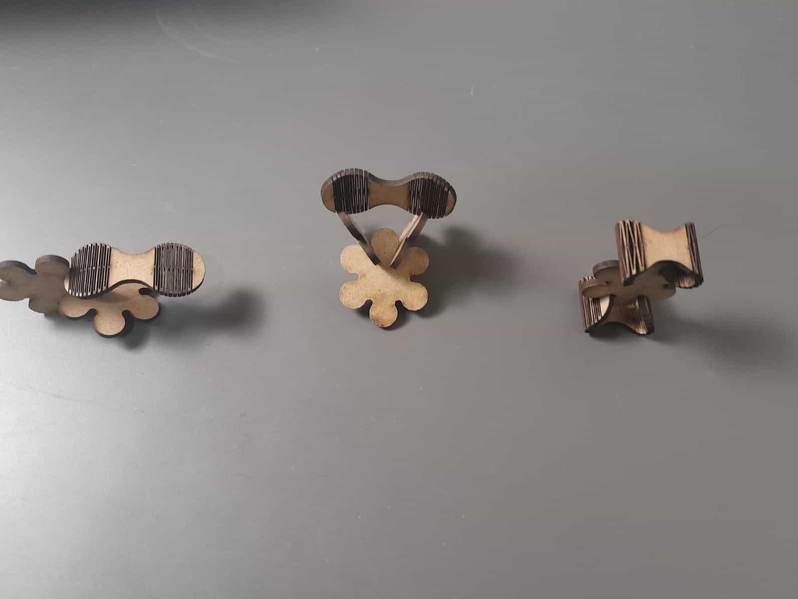
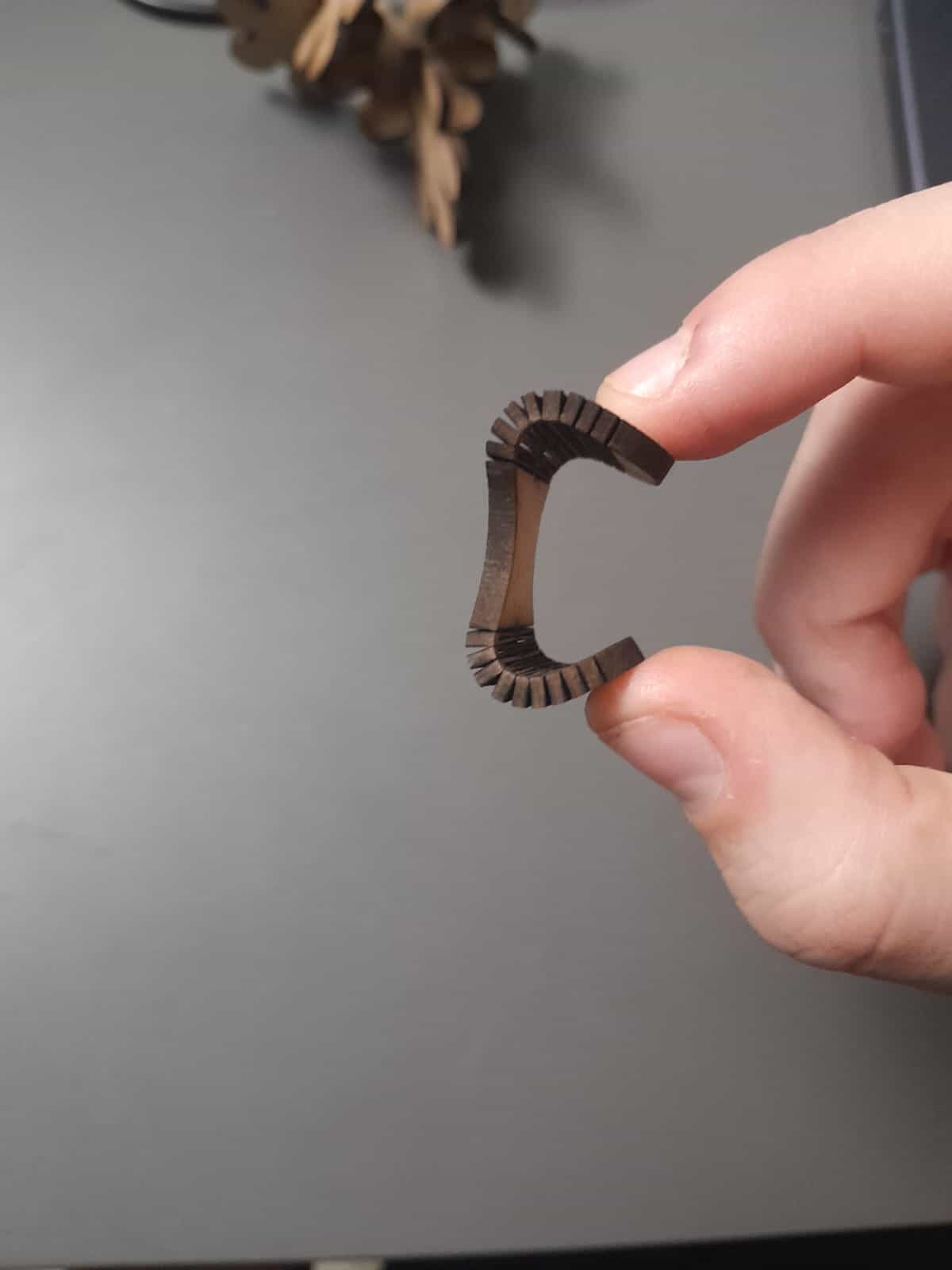
Regarding design and assembly, we researched various techniques that do not require screws or glue. We examined assemblies such as fixed pressure joints, which simplify the construction of quick and efficient structures. Additionally, we developed "live hinges" in SolidWorks, which are cuts created to allow the material to bend without breaking.
Grupal Task Week 3How does a laser cutter work?
A laser cutter uses a precise and concentrated beam of light (laser) to cut, engrave or cut materials. The laser, usually CO2, is generated and focused through a lens that concentrates it into a point. This beam of light has a high energy that vaporizes or melts the material in the contact zone, allowing cutting or engraving with high precision and without “physical” contact.
| Field | Uses in Engineering | Uses in Food | Uses in Art | Uses in Medicine |
|---|---|---|---|---|
| Prototyping | Precise cutting of parts for functional prototypes, complex structures, and assemblies. | Cutting of packaging, labels, and customization of food products. | Creation of artistic models and prototypes for sculptures with fine details. | Creation of prototypes for medical devices and customized prosthetics. |
| Manufacturing | Cutting of parts for machinery, structures, and electronic components. | Design and cutting of templates for decorative foods, such as cakes and chocolates. | Sculpture and modeling of materials such as wood and acrylic. | Production of anatomical models or surgical tools. |
| Industrial Design | Production of customized parts, molds, and dies. | Customization of packaging and labels for food and beverages. | Creation of personalized items such as jewelry, watches, and decorations. | Creation of tools and molds for medical device manufacturing. |
| Education | Development of didactic projects and research for engineering students. | Production of educational materials related to the food industry. | Realization of educational and artistic projects in schools and universities. | Fabrication of educational models of anatomy or medical equipment for learning. |
| Architecture | Modeling and cutting of materials for architectural models. | Customization of decor for food events, such as menus and ornaments. | Design of artistic models and scaled models for presentations. | Modeling of medical or surgical designs to visualize structures. |
| Digital Manufacturing | Customization of products, such as printed circuits or electronic components. | Creation of packaging or innovative decorations for product presentation. | Painting, engraving, and customization of surfaces on art objects. | Fabrication of customized medical devices or implants. |
My work on lasercut
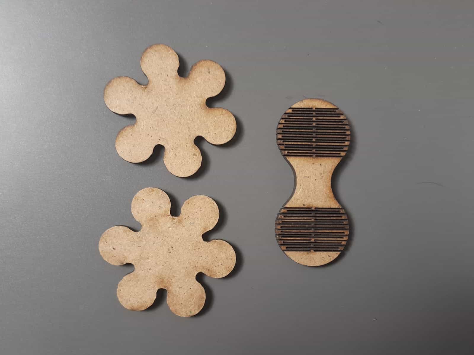
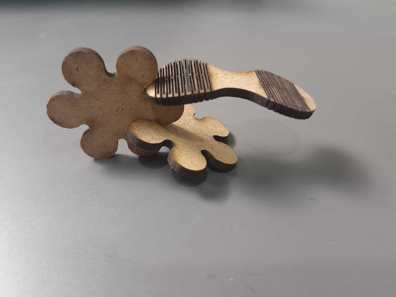
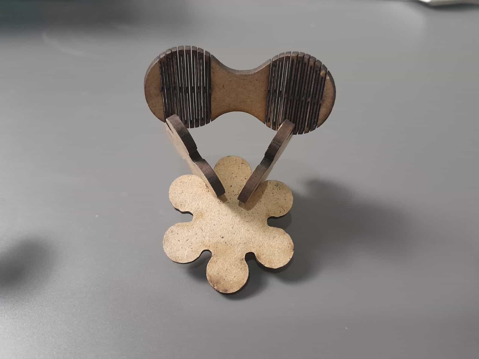
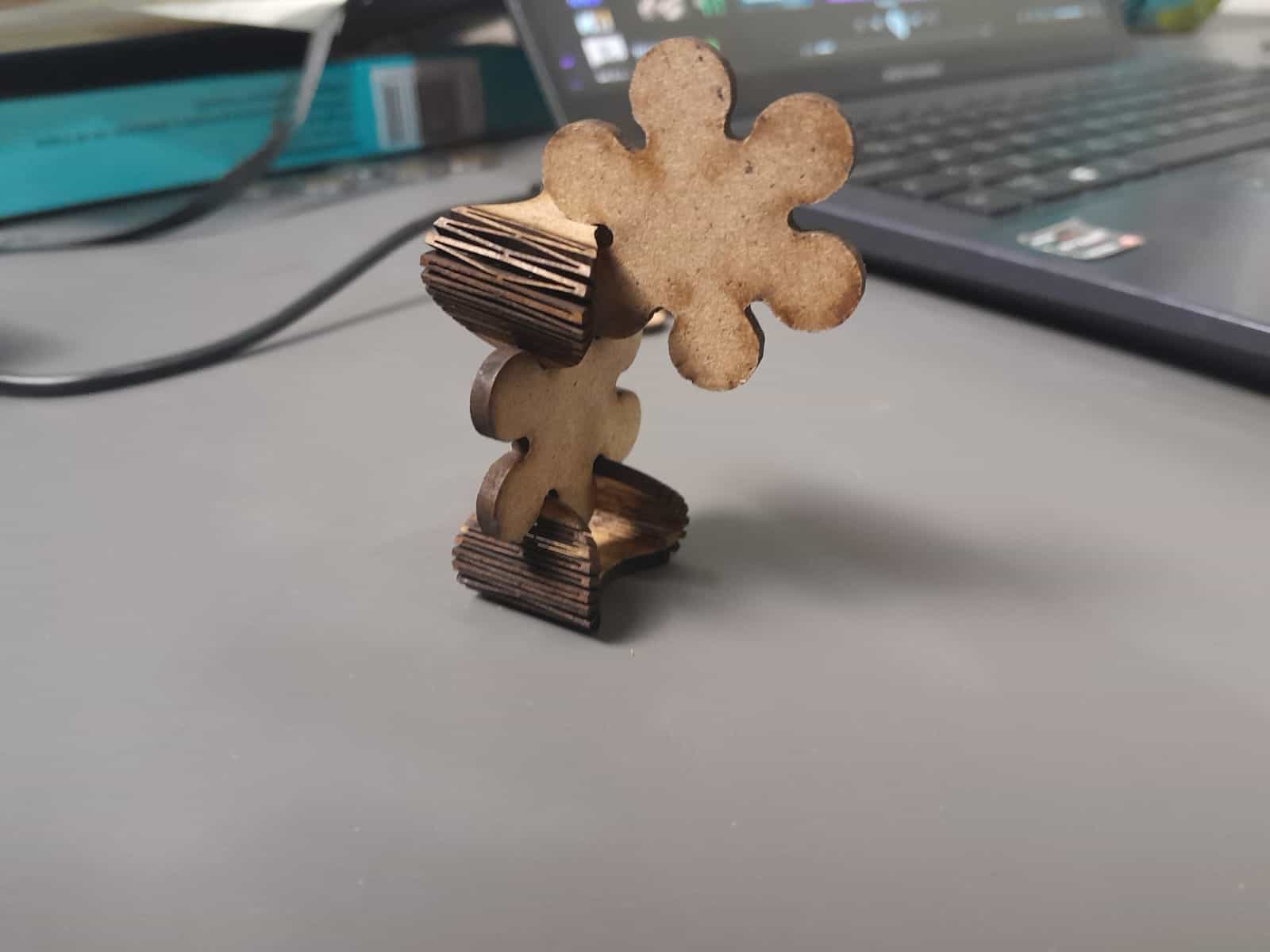
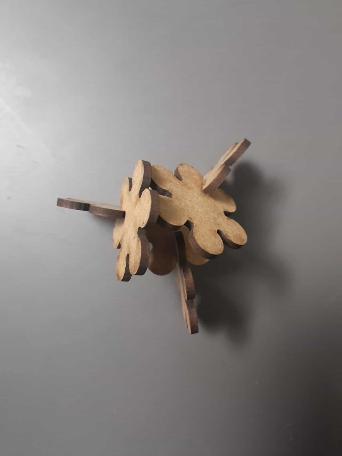
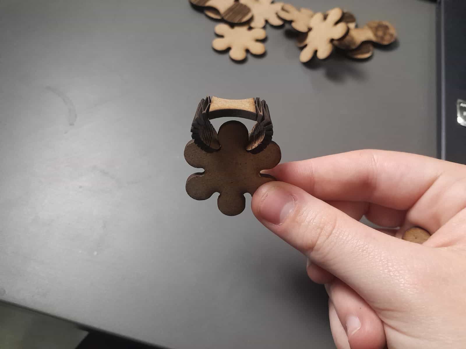
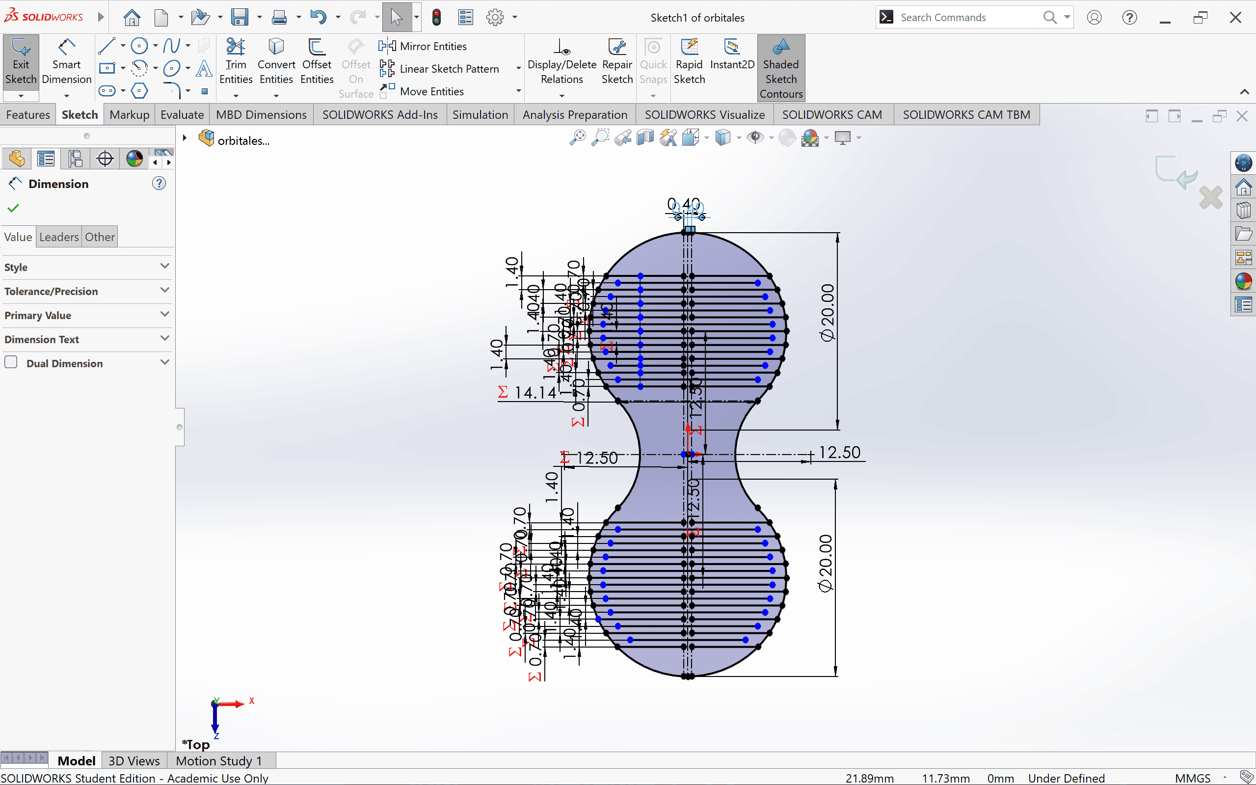
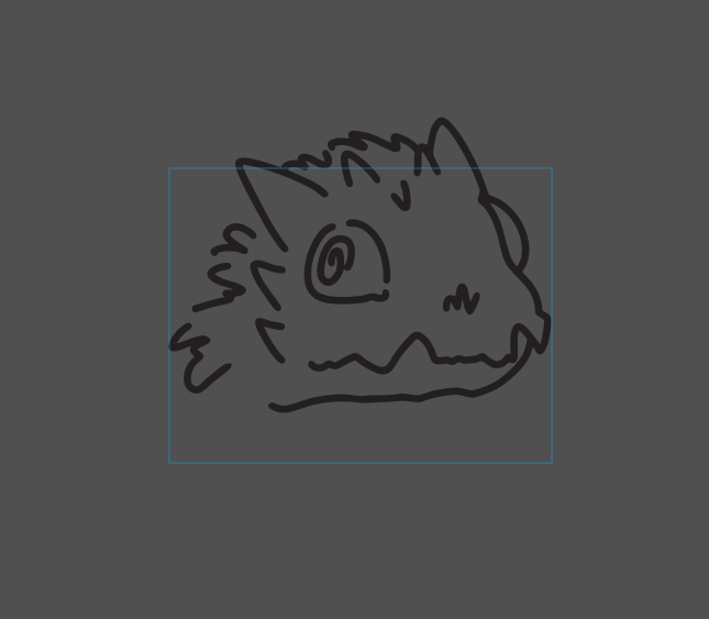
For this week I designed two pieces for laser cutting, inspired by atomic orbitals, because I always found the topic about them somewhat interesting, so based on their shape I designed two pieces.
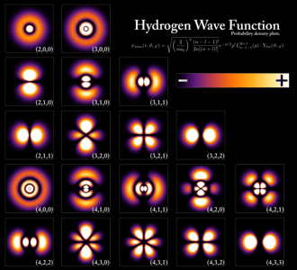
(Orbitals are regions of space around the nucleus of an atom where there is a high probability of finding an electron. They are based on the Schrödinger equation and describe the quantum behavior of electrons in atoms.)
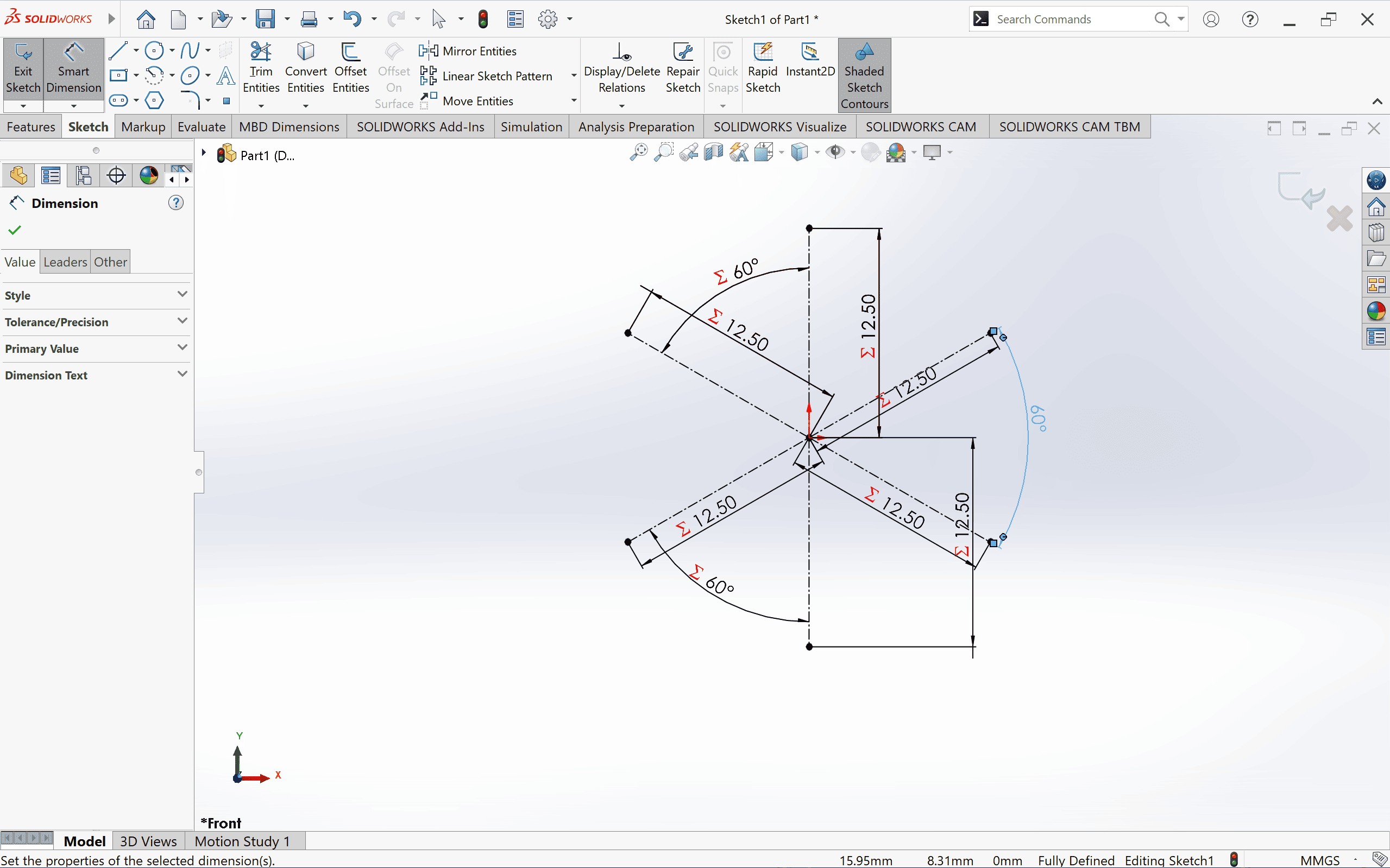
Solidworks
For this we will use the global variables but... what is this and how do I create one?
In SolidWorks, the global variable is a value defined at the document level that can be used in various dimensions and relationships within a sketch or model.
Steps to create a global function (variable) in SolidWorks:
| Step | Description |
|---|---|
| 1. Open SolidWorks and the model | Make sure you have an open piece. |
| 2. Go to Equations | Go to the toolbar and select: Tools → Equations... You can also press Alt + T + Q as quick access. |
| 3. Create a global variable | In the equations window, click "Add". In the column of Name, write the name of the variable (example: Plate_Width). In the column of Value, enter the desired number (example: 50mm). Press Enter to save. |
| 4. Use the variable in dimensions | In a sketch, select a dimension. In the dimension edit box, type the variable name with the prefix = (Example: =Plate_Width). Press Enter and the dimension will be linked to the global variable. |
| 5. Modify the global variable | If you need to change the value, go back to Equations and edit it. When you make changes, all dimensions linked to the variable will be updated automatically. |
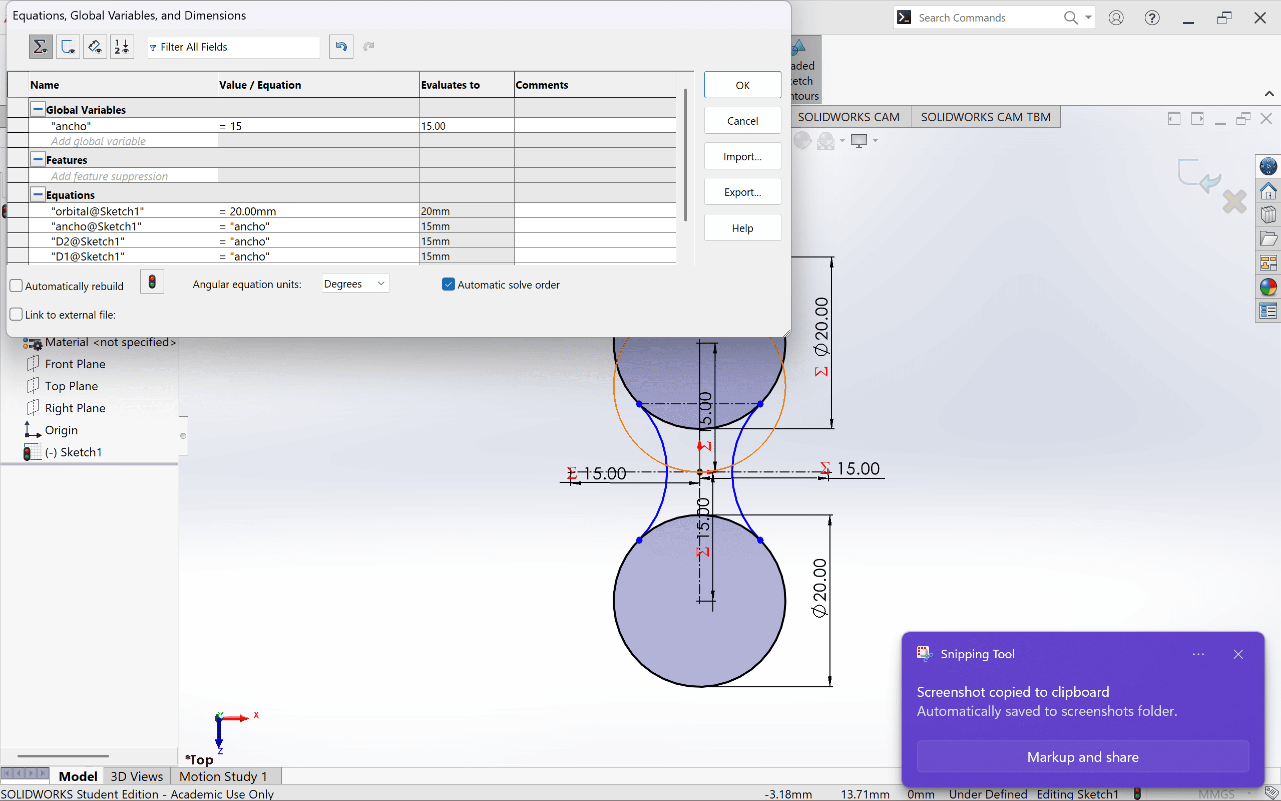
Here you can see the dialog window with a table about the global functions.

what is kerf? And why is so important?
Kerf is the width of material that is removed during a cutting process, such as using a laser, saw, water jet or plasma. Basically, it is the space or groove left after making a cut.
Factors affecting kerf:
How a Vinyl Cutter Works
| Process | Description |
|---|---|
| Digital Design | The design is created in software such as Adobe Illustrator, CorelDRAW, Inkscape, or the cutter's proprietary software. The design must be in vector format (SVG, DXF, AI, etc.). |
| Machine Setup | The vinyl is loaded into the cutter, and parameters such as pressure, speed, and blade depth are adjusted according to the material type. |
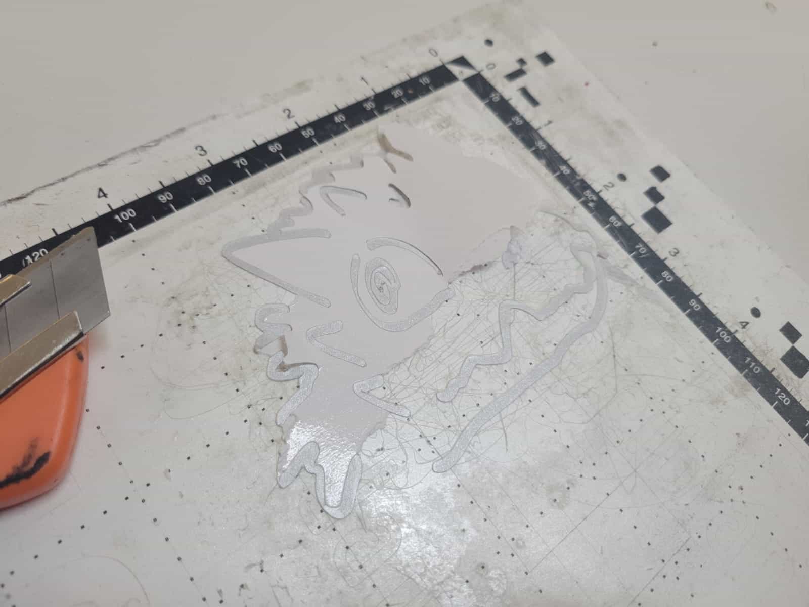
| Vinyl Cutting | The machine moves the material while the blade precisely cuts the design following the vector lines from the file. It only cuts the top layer of vinyl without piercing the backing paper. |
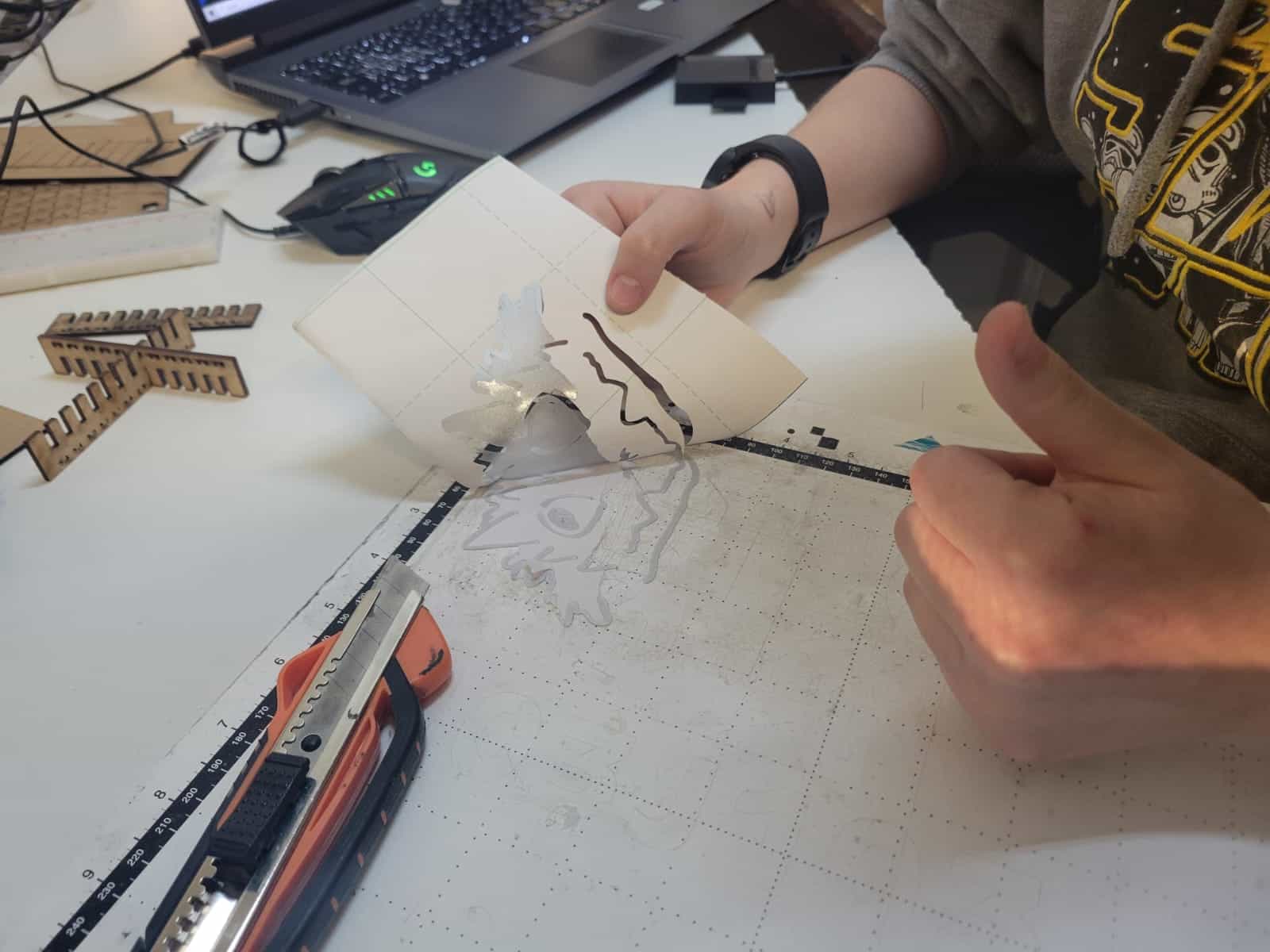
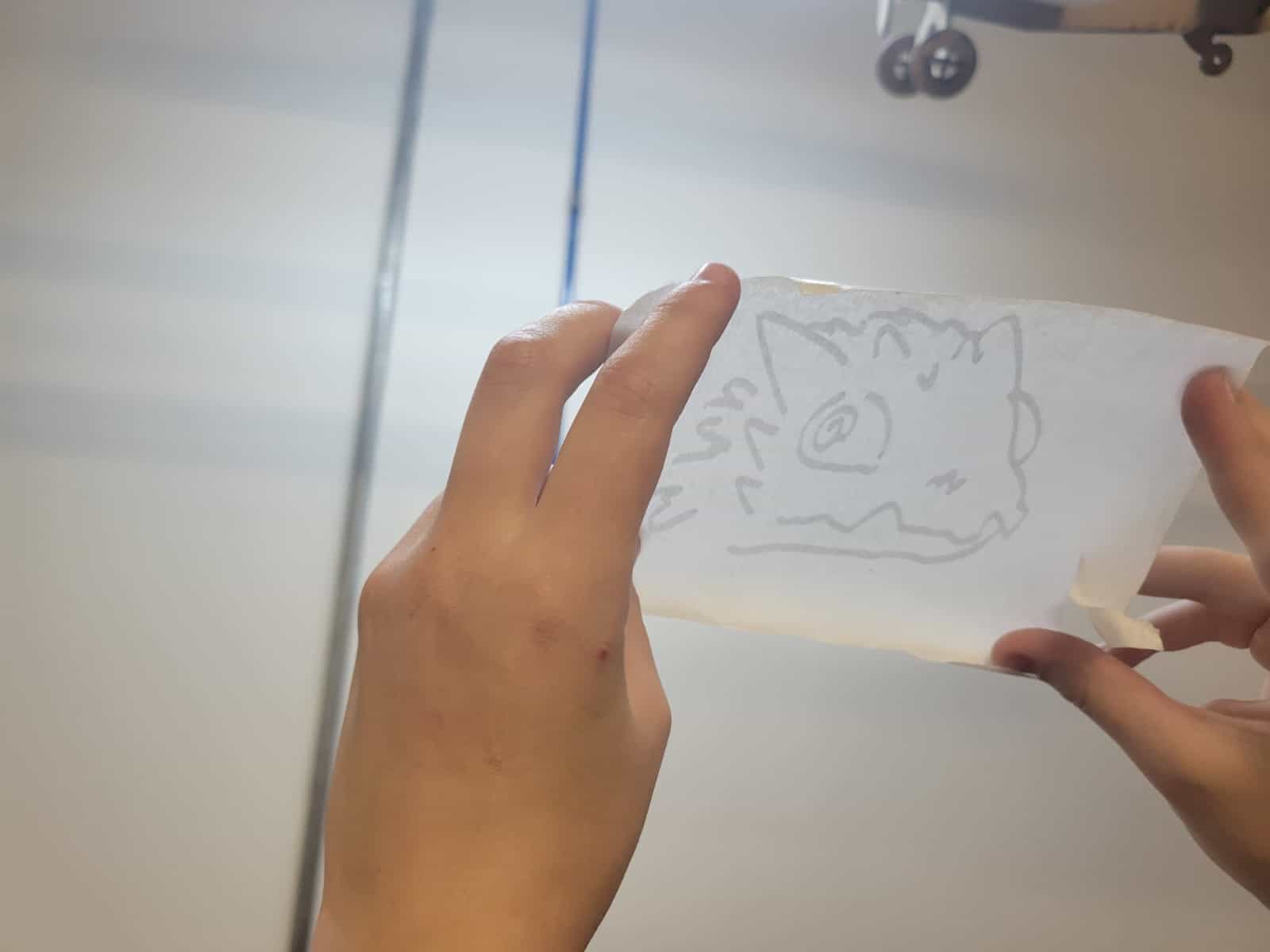
| Weeding | The excess vinyl that is not part of the design is removed using tools such as tweezers or special hooks. |
| Application of Transfer Tape | A special adhesive tape is placed over the cut design to transfer it to the desired surface without losing its shape. |
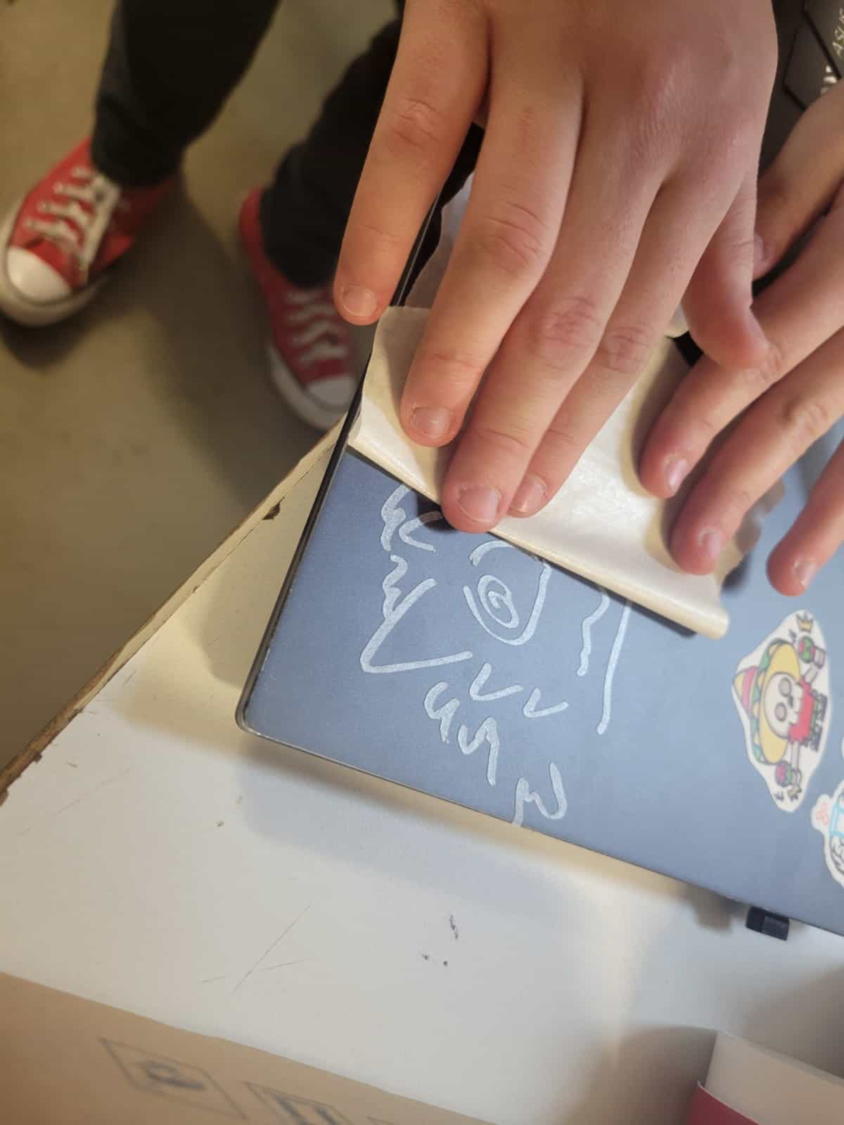
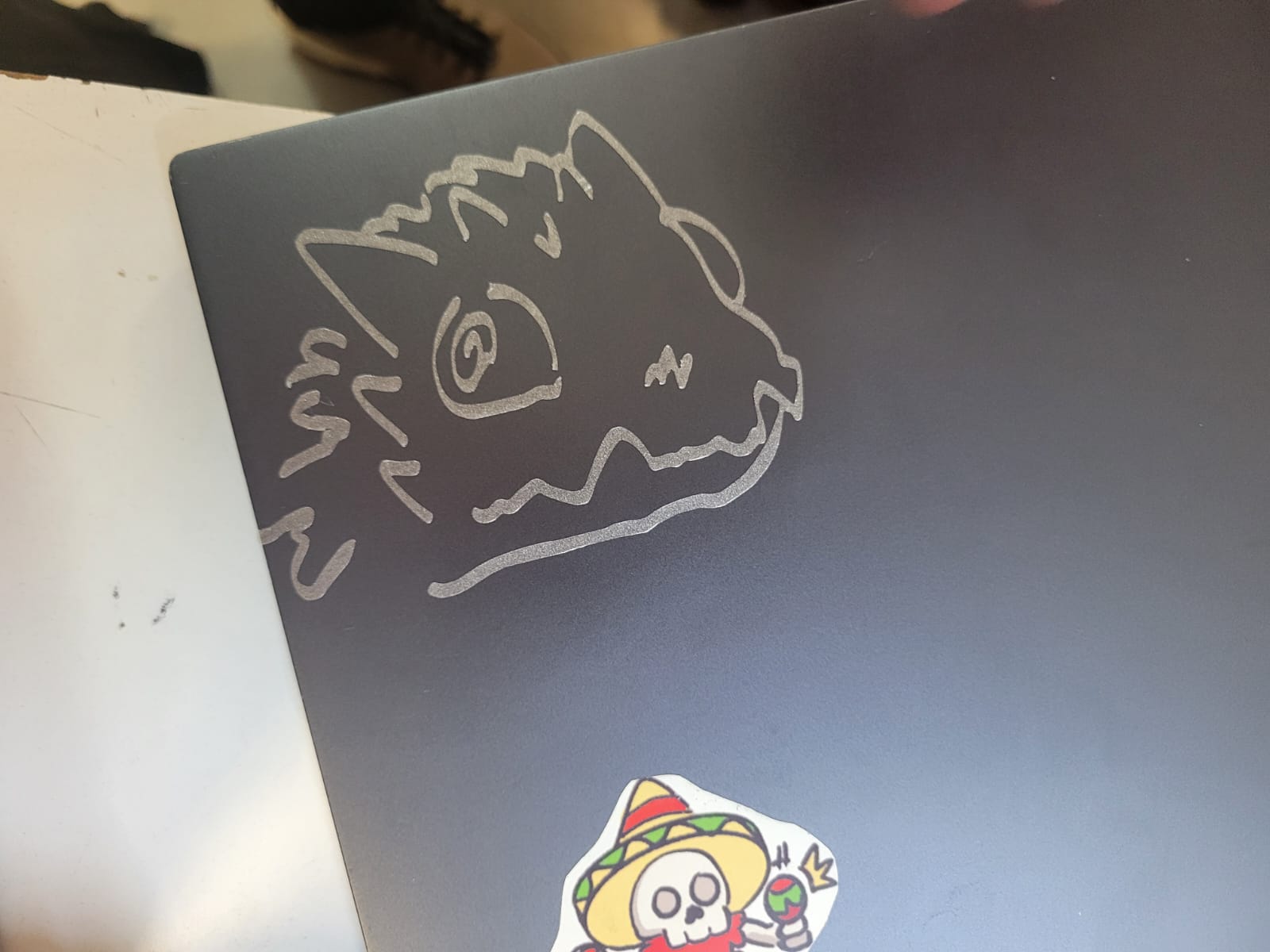
| Placement on the Final Surface | The design is applied to the surface (glass, metal, wood, plastic, etc.), pressing it with a squeegee to avoid bubbles and ensure adhesion. |
| Removal of Transfer Tape | The transfer tape is slowly removed, leaving the vinyl precisely adhered to the surface. |
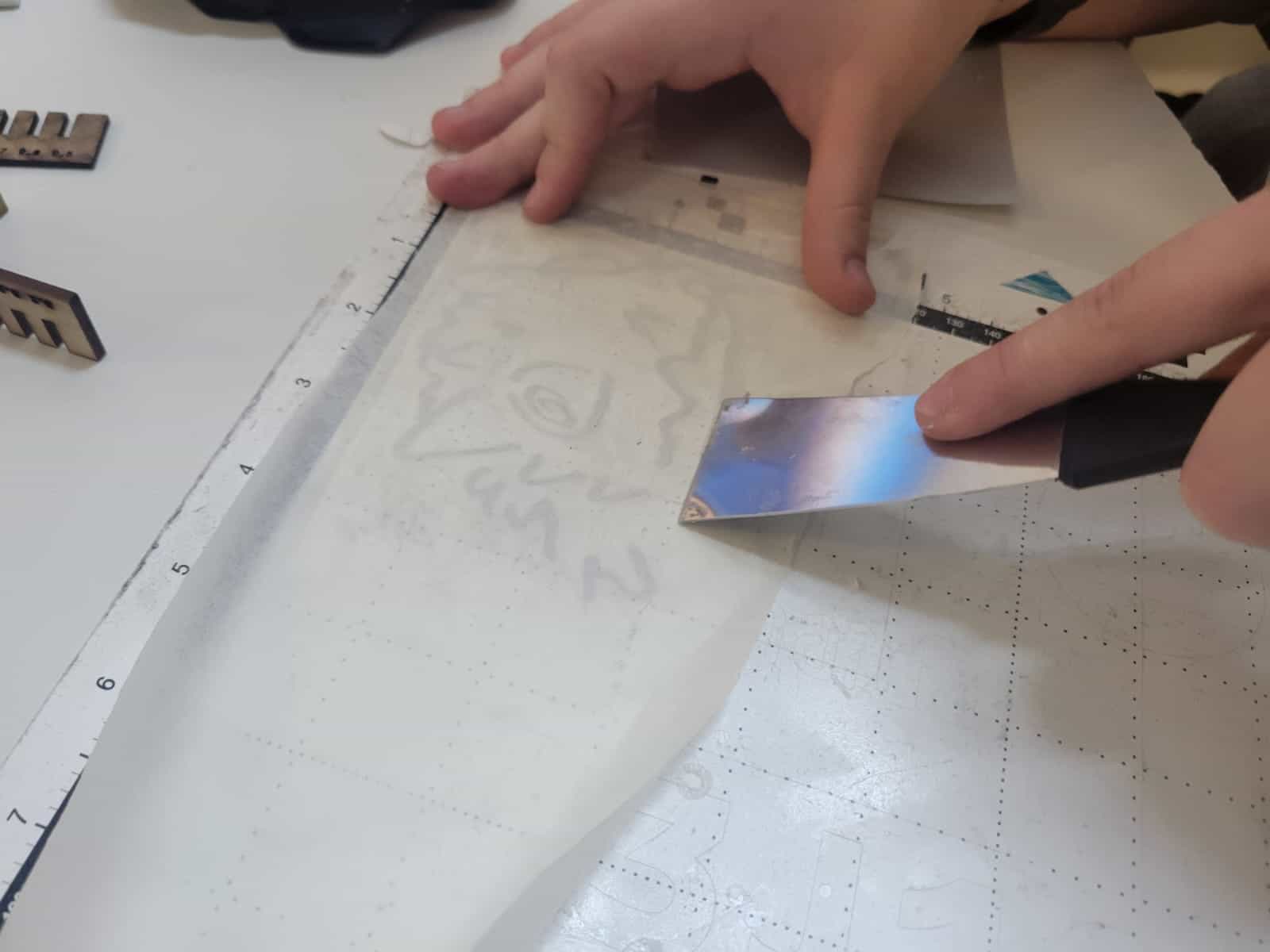
Cutting process
The appropriate cutting head is selected (there are different blades and markers) and the design is loaded from a USB. If the image is not vectorized, it must be edited in software such as Inkscape. The position of the layout on the screen grid is adjusted, ensuring it matches the physical mat. Parameters are configured such as speed and cutting pressure, adjusting them according to the level of detail required. The cut is started and it is checked that the result matches the original image. Lastly, transfer paper is used to adhere the vinyl to the desired surface.