13. Molding and Casting
This week, I made a mold for the die I will use for my final project. We also did a group assignment, which you can find here.
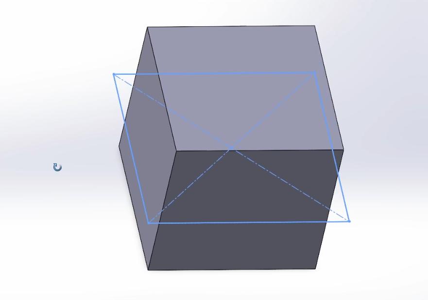
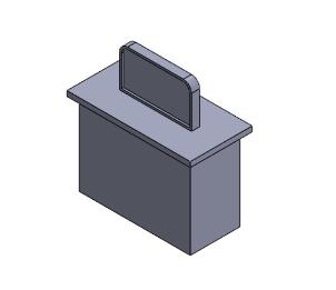
Before making the mold, I searched how to design a die on SOLIDWORKS. I didn´t want to make a cube with sharp corners. I wanted to make a die with round corners like this:

I found a YouTube video where they explain how to build one from scratch. I based my die design on the video, but with some changes.
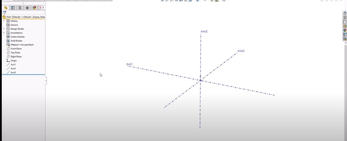
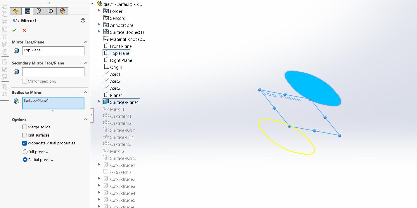
I added 3 reference axes:
Then added a reference plane 35mm from the Top Plane
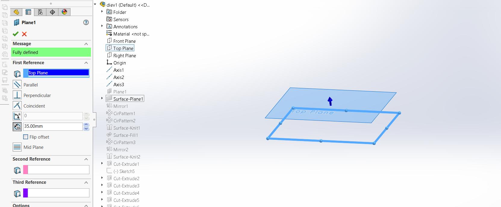
On that plane I added a sketch with a rounded square with the dimensions I wanted.
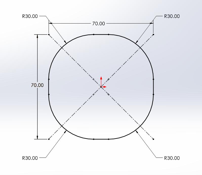
It would measure 7x7x7 cm
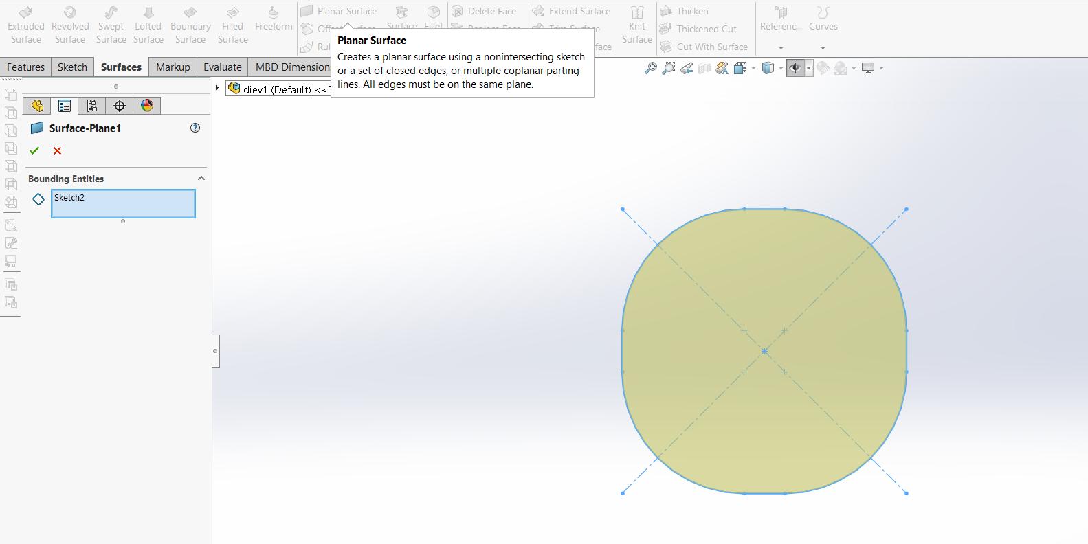
I used the Planar Surface tool to make it a surface:
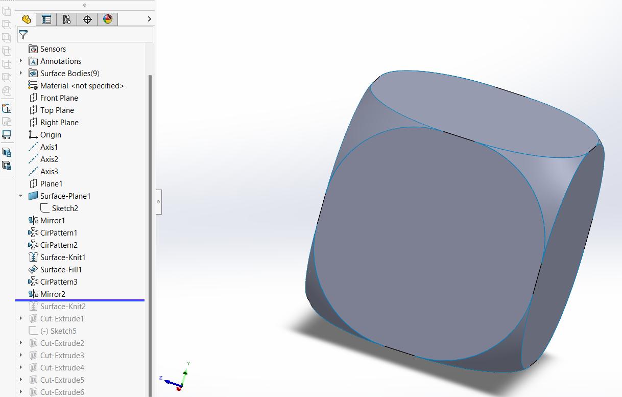
With the mirror and the circular pattern tools, I added the other 5 faces to have a cube.
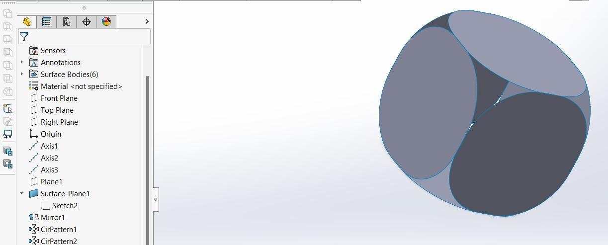
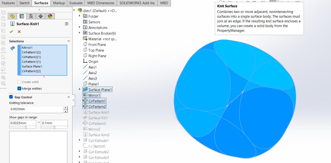
I used the knit surface tool to have a single surface.
With the Filled Surface tool I made the first corner, this tool fills the gap between the selected faces.
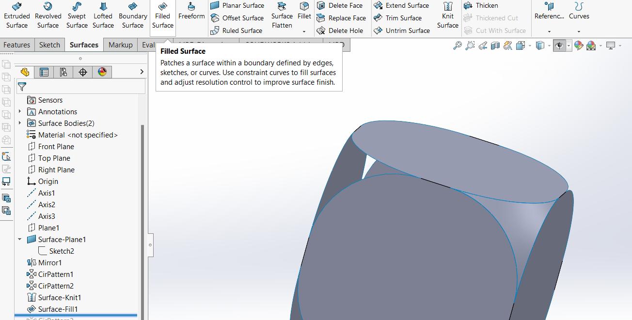
Using the mirror and circular patter tools I added the remaining corners.
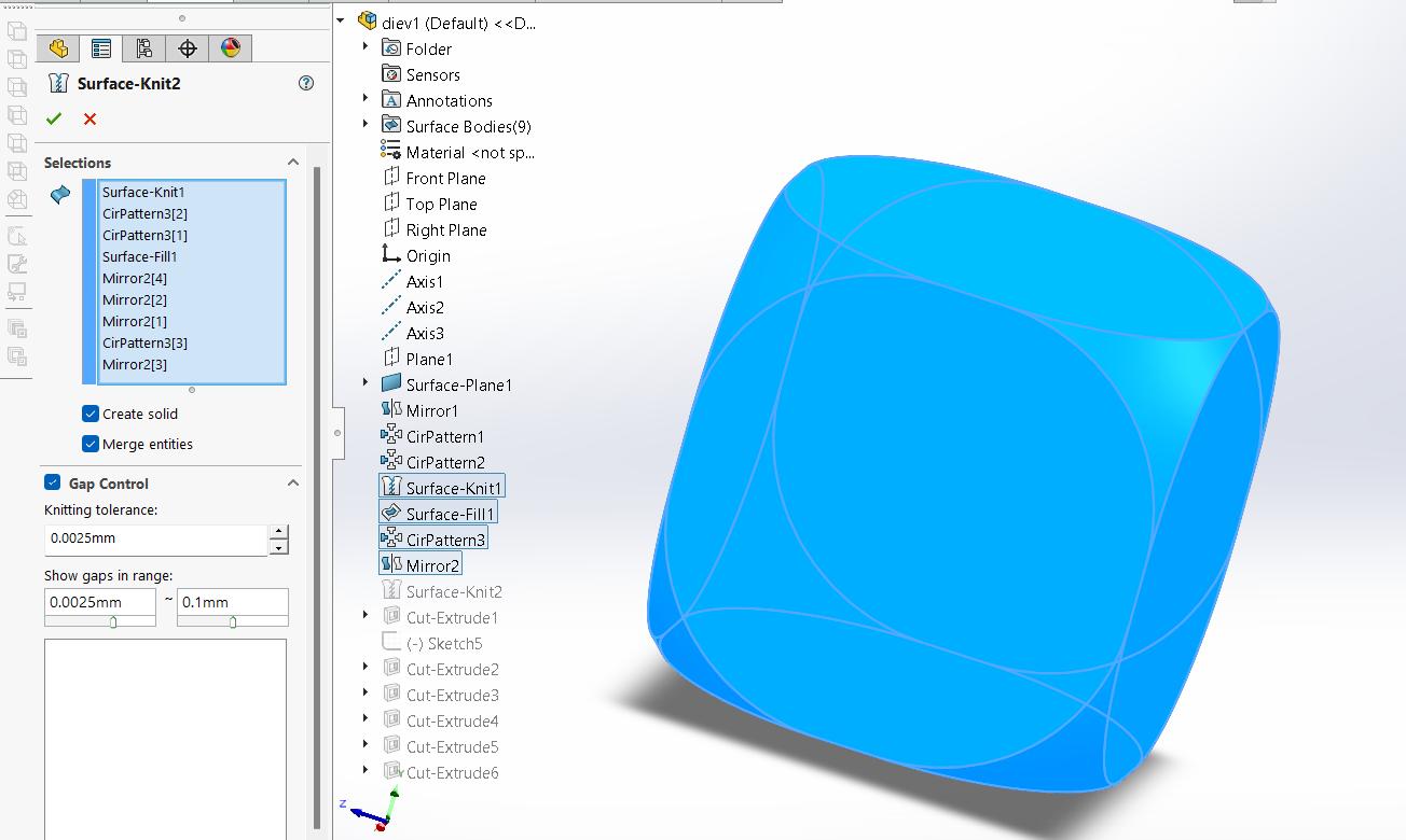
One again I used the Knit Surface tool, but I checked the Create solid box to merge everything together and have a solid instead of a surface.
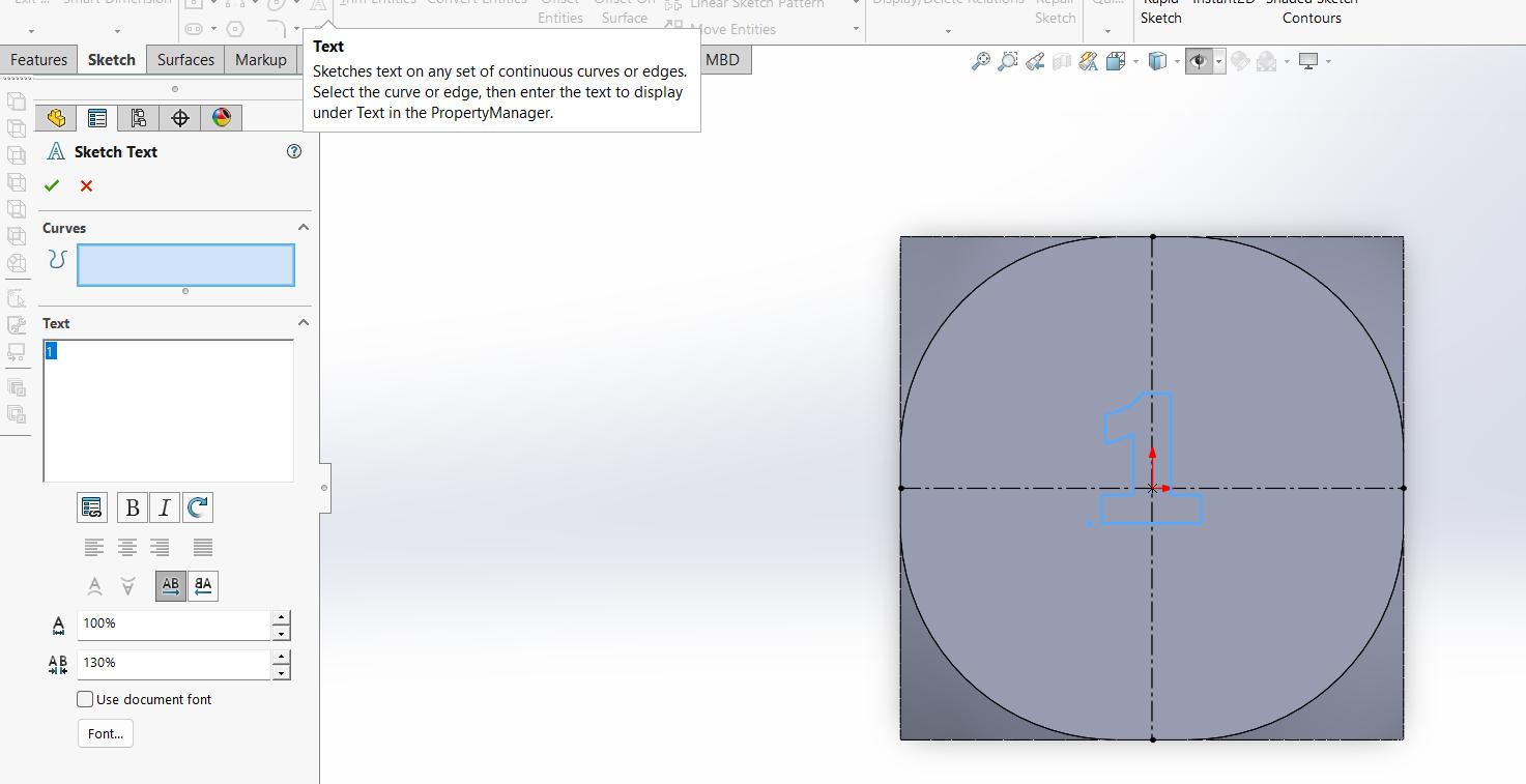
Once I had a solid, I added the numbers on each face, I put each number on the right face. So, 1 is opposite to 6, 2 to 5, and 3 to 4. I used the text tool to draw the number, I selected a font and a big letter size.
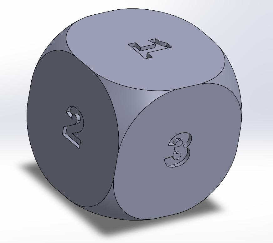
I used the Extruded cut tool with a 2mm depth to engrave the numbers on each face, and here´s the result:
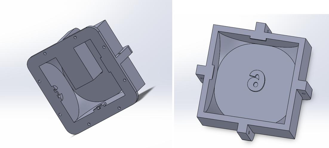
After finishing the die, I started designing the mold. I was planning to put a XIAO nfr52840 inside the die, so I needed to be able to remove a face to insert the board. I opened a copy from my die to make some modifications.
I extruded the face containing number one from the die:
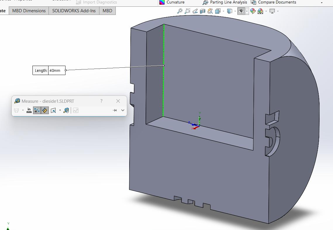
The hole I made is a little over half the die´s height, so I can place the board at its center.
To make the hole I measured the PCB I built for the board:
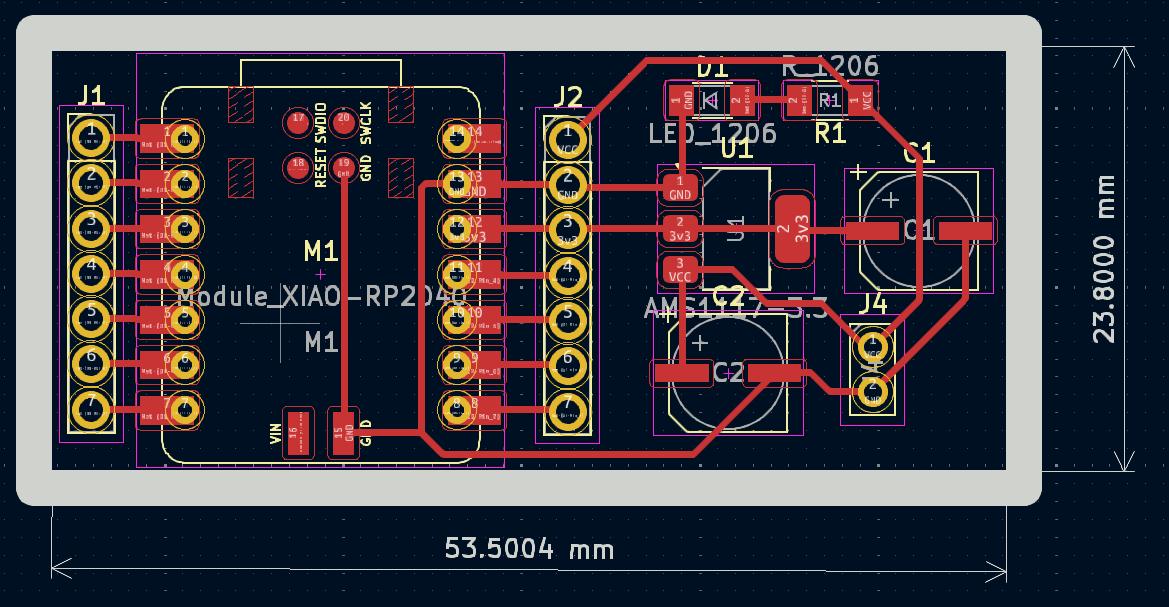
I considered a 54x24mm square so it could fit easily.
To make the piece I just cut from the die, I opened a new file and clicked on Insert>> Part.
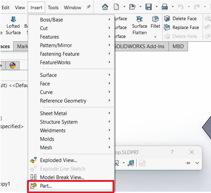
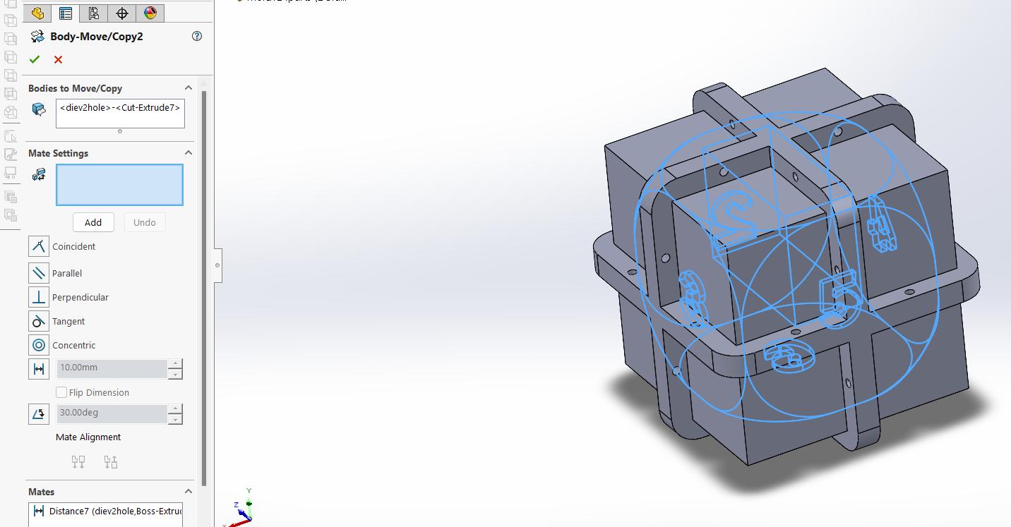
I inserted the original die and the one with the hole, then I used the Move/Copy tool to move the parts together:
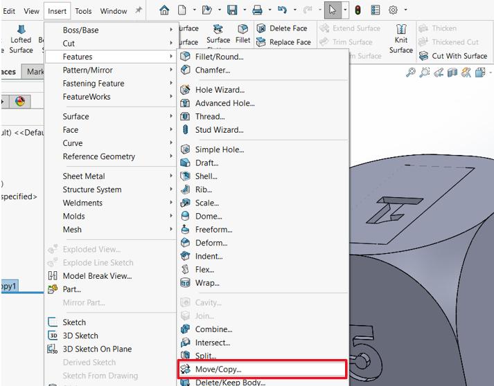
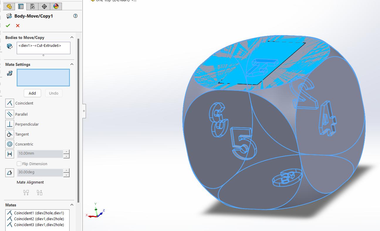
This tool allows us to move the parts and fix them together like an assembly by adding mates.
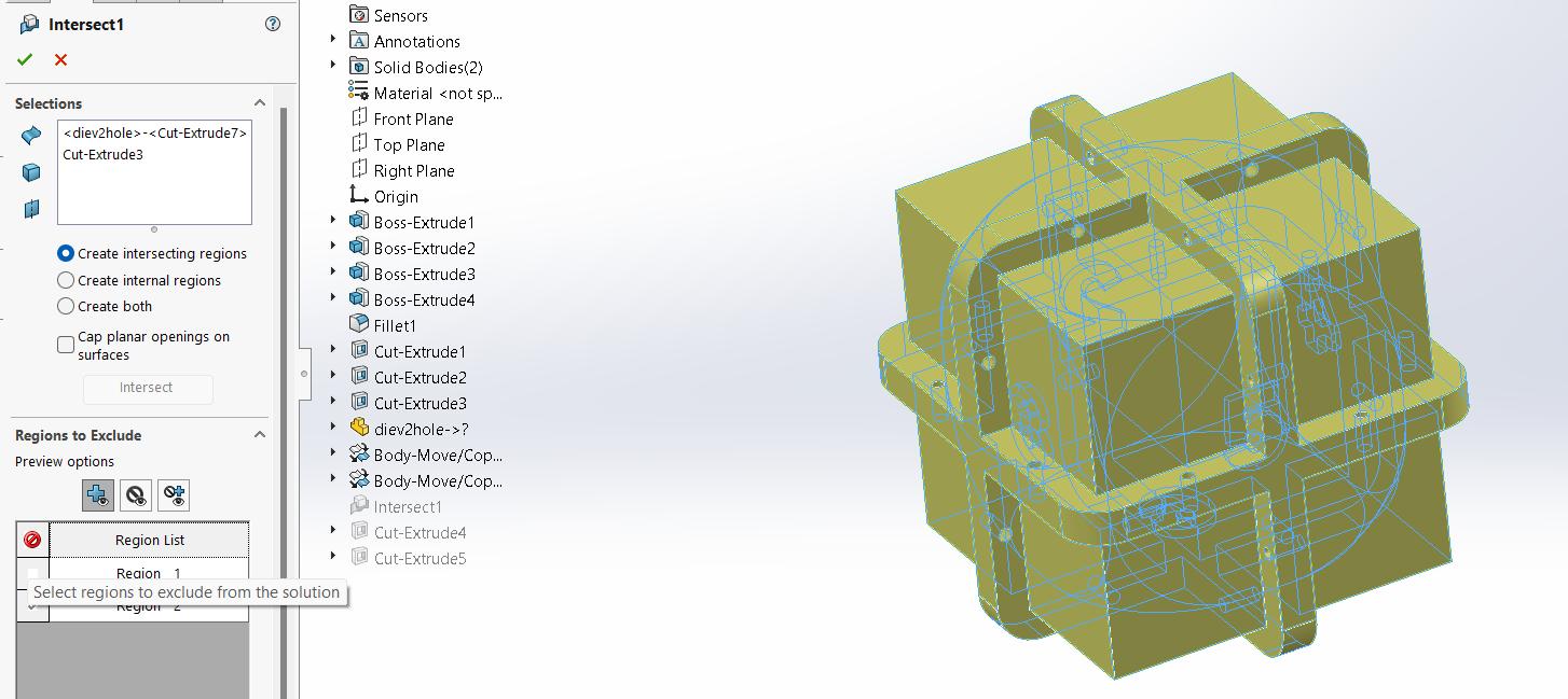
After having both parts in the same place, I used the Intersect tool to basically subtract the bodies and leave the face I removed from the die.
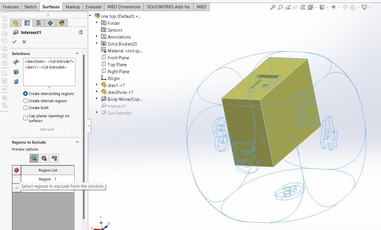
This tool can be found on the same menu as the Move/Copy tool. I clicked on Create intersecting regions and excluded Region 2, which was the die I made with the hole. By doing this I got only the part I had removed as a new body.
Since the board will use some space inside my die, I used the Cut Extrude feature to make the body I just created to make it a little shorter.
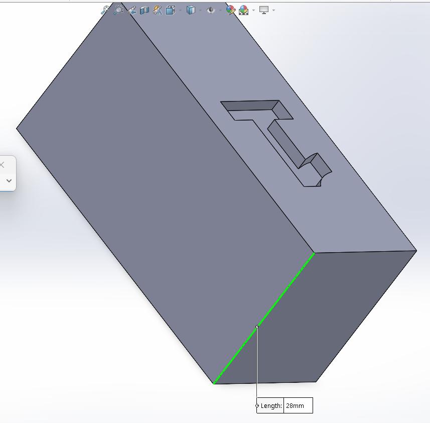
The hole the die has is 40mm and the number one is 28 deep which leaves a 12mm gap for my boar to fit inside the die.
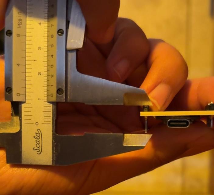
I measured the PCB´s height to make sure I left the right amount of space.
It was time to make the mold. I spent most of the time thinking about how many parts I should design to make it. I planned to make the die from a soft material like silicone, so I only had to make a negative mold, but I wasn’t sure if two parts would be enough to unmold the die easily. My advisor showed me a video on how some masks were made using molds, but the mold consisted of more than two parts, so I decided to divide the mold into four parts.
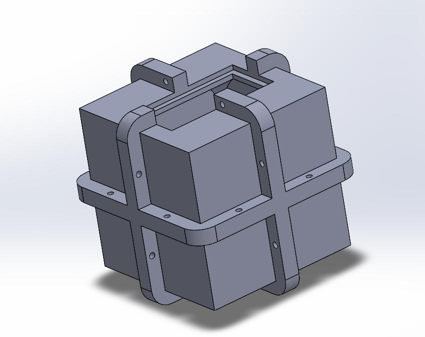
I opened a new file on SOLIDWORKS and created a cube of 80x80x80mm. Since the die was 70x70x70mm, I had 5mm of wall thickness (this file was going to be the general idea of my mold, which then I would turn into the four parts).
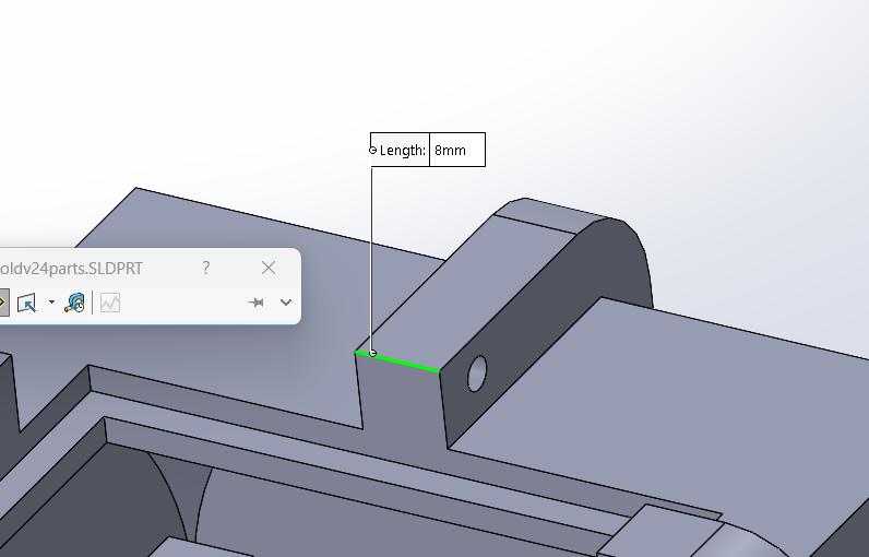
I added some "Bolting Flanges" in the middle of each face so I could bolt everything together with M3 screws:
Once I had the outer part of the mold, it was time to make it hollow with the die´s shape. To do so, I inserted the die with the hole and followed the steps I took to make the cover with the number one.
I used the Move/Copy tool to put the die inside the mold.
And I used the Intersect tool so subtract the die from the mold.
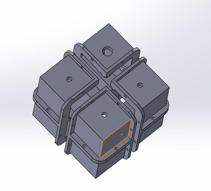
Now I had a negative mold to create my die:
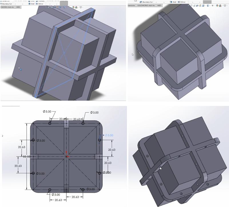
I just created two sketches with a square (90x90mm) on each sketch in two different planes to cut the four parts. I made four copies of the file and changed the direction of the cuts to get them:
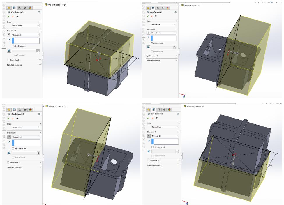
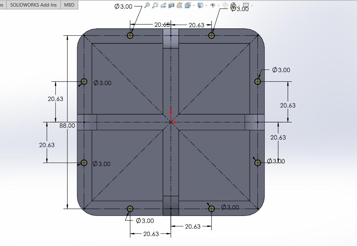
I added some holes to the top part of my mold so I could pour the silicone inside.
Early in the process of designing the die, I realized I had to print the mold in 3D to get the numbers engraved. If I wanted to make a die with no numbers, I might´ve used a CNC Router. Since Fused Deposition Modeling (FDM) printers extrude molten plastic filament layer by layer to build a 3D object, they don´t make a smooth surface, so I had to use Digital Light Processing (DLP). These printers use a UV laser or light source to cure liquid resin, layer by layer, to create a 3D object. This results in intricate details and smooth finishes, perfect for making molds.
At my local Fab, we have two resin 3D printers, an Elegoo Saturn 2 and an Anycubic Photon Mono M5s. I downloaded Chitubox as my slicer since my local advisor gave us a small explanation about how to use it, and since it is compatible with both printers.
Chitubox is like any other slicer: import a STL file, add supports, and slice it. The biggest difference was that I had to configure the resin I was going to use. So, I ran to the Fab Academy office to get a resin bottle before anyone else.
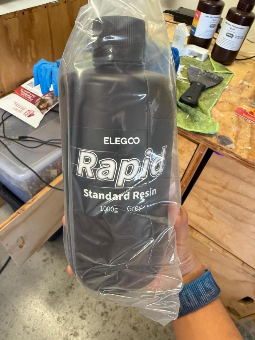
I got an Elegoo Standard Resin in Grey
I browsed Elegoo´s website to find out how to configure the slicer for this resin, and I stepped into this file. Here I found the recommended settings for the printer and the resin I used.

Inside Chitubox, I selected the printer I used, and it automatically gave me the printing area and resolution:
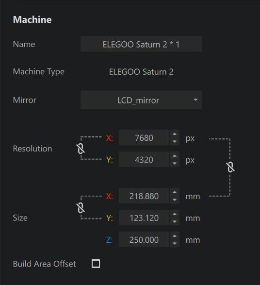
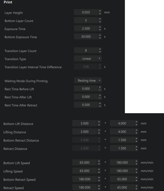
On the print section I put the parameters I got from the Excel sheet:
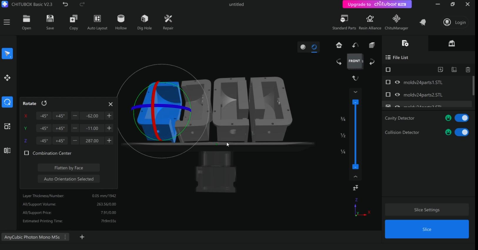
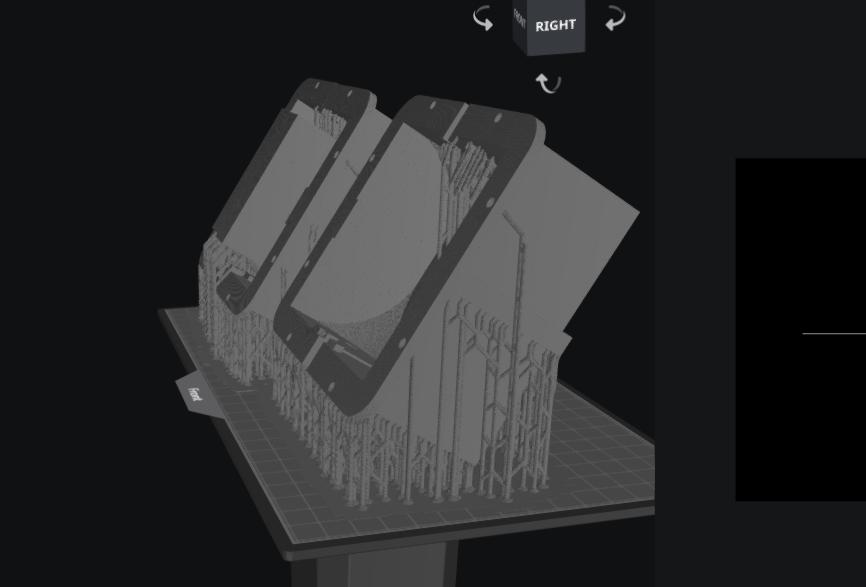
After configuring the printer settings, I imported the STL file and fixed them in place.
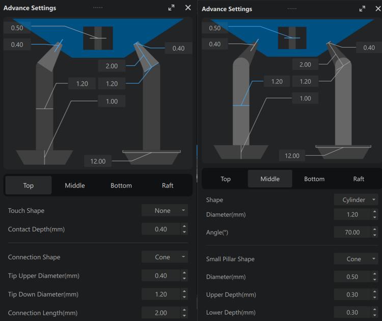
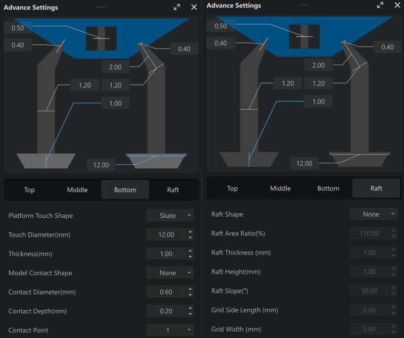
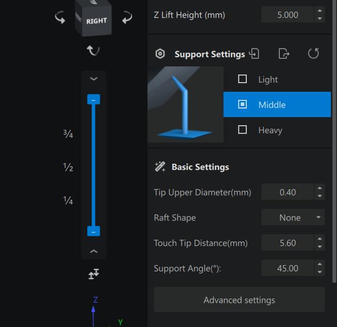
I selected medium supports with a Touch Tip Distance of –mm, all the other settings were left as default, as the following images show:
After that, I clicked the Slice button and saved the file to a USB drive.
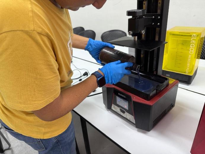
I poured the resin into the printer´s container, connected the USB, and started printing.
Once it was ready, I cleaned the pieces with Isopropyl alcohol.
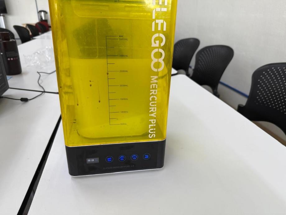
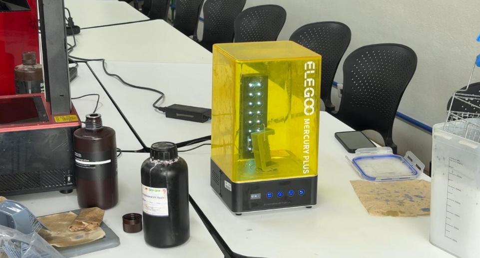
I used an Elegoo Mercury Plus; it has a container where you can put the Isopropyl alcohol, and with the washing mode, it creates a vortex, which helps to clean the pieces. I set the cleaning time to 8 minutes.
I removed the supports before curing them, so it was easier.
[mercury video]
Then I took the pieces out of the recipient and used the second mode to cure the pieces, I put each one to cure for 7 minutes.
Once I had all the parts ready, I tried to see how well they assembled and I noticed they weren´t perfectly flat, leaving a gap where the silicone could leak, so I bought a sheet of black foamy and cut some pieces to match the mold´s perimeter so I could put them between the mold´s parts.
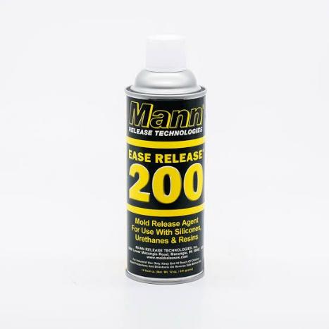
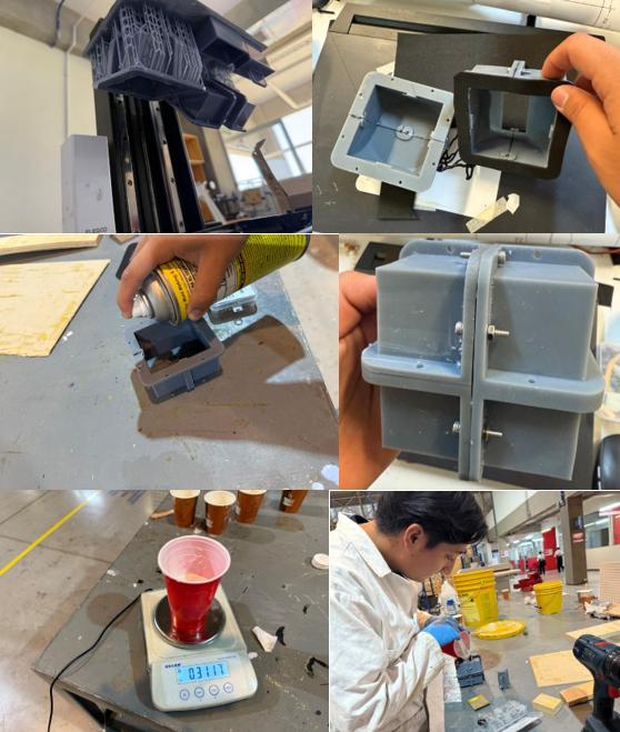
Before screwing the mold, I applied some Ease Release 200, which would help me to unmold the die once the silicone dried.
Then I assembled the mold together:
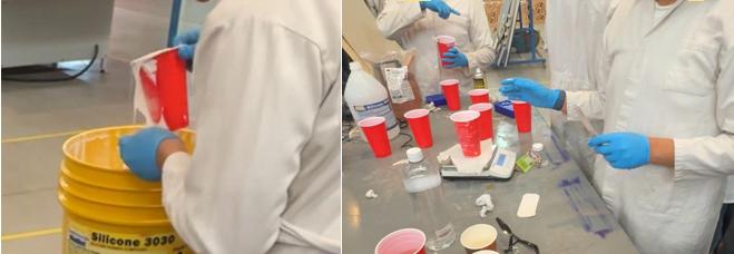
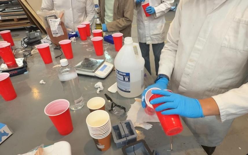
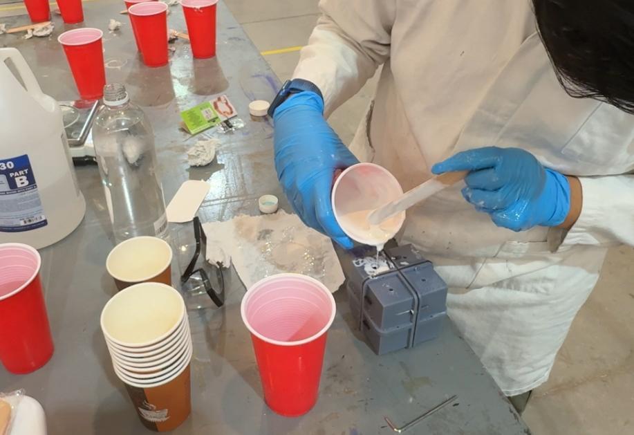
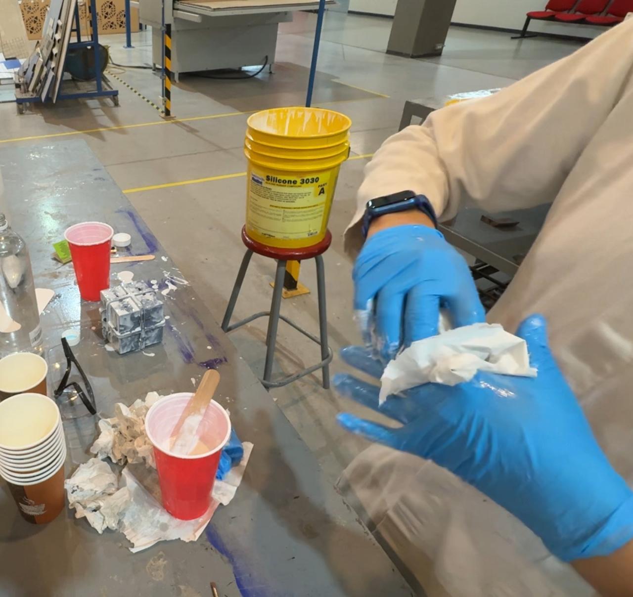
To prepare the silicone, I added water to measure its volume, poured it into a cup, and marked the water´s level. I used Silicone 3030 to make the die.
SILICONE 3030 is a low-viscosity and easy-to-use condensation silicone for mold construction. I found a PDF containing its specifications, I found the ratio is 100A:10B.
Keeping that in mind, I added component A into the cup just below the mark. I weighed it using a scale.
It weighed 250 grams, so I had to add 25g of part B.
Then I started mixing it.
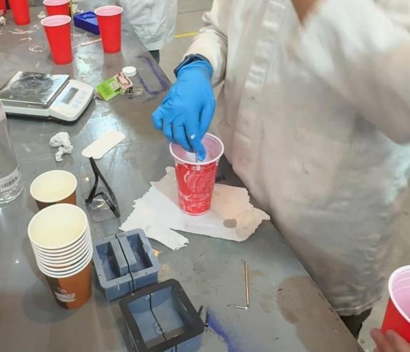
I started pouring it into the mold, but the silicon´s viscosity was higher than I expected, so it was hard to fill the mold in time.
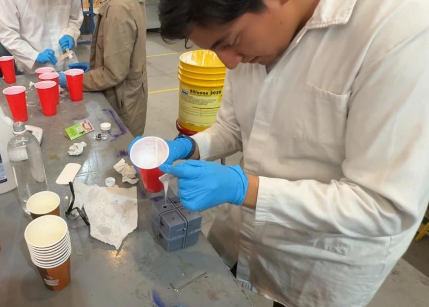
The silicone started hardening, and I had to make a new mixture, but again, I was taking too long, so the silicone hardened again.
The hole I made was too small to pour the silicone inside the mold, so I decided to separate the mold in two parts, add the silicone and screw both parts together.
[Messy video]
Due to the silicone´s viscosity, when I tried to get both parts together, it started leaking, and the foam I cut moved out of place, leaving a huge gap. So, I ended up with a huge mess.
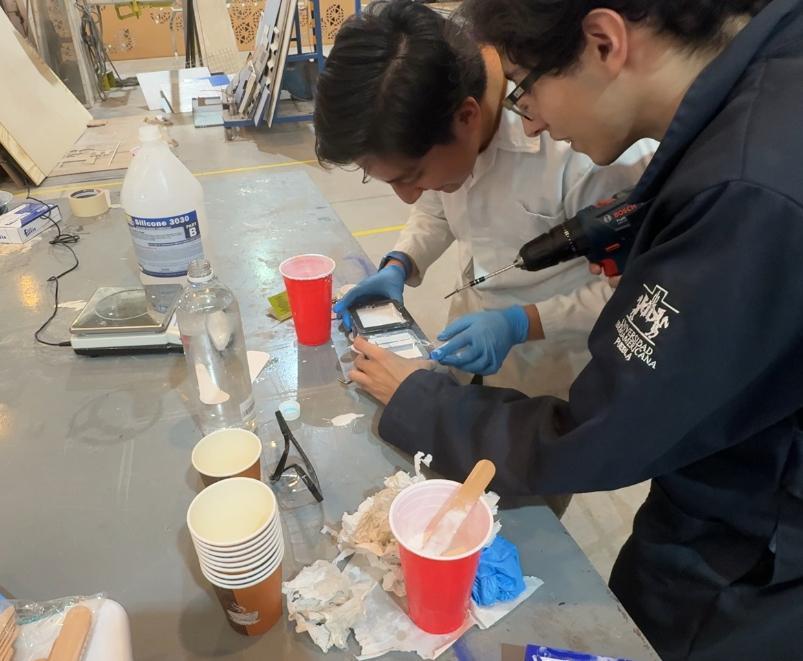
A big shout out to Carlos who helped me through this mess.
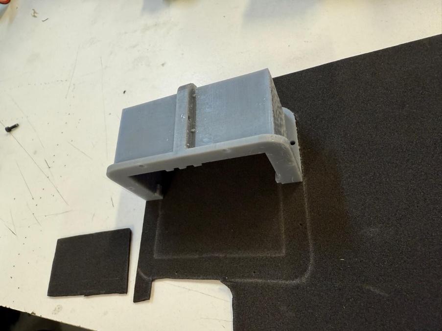
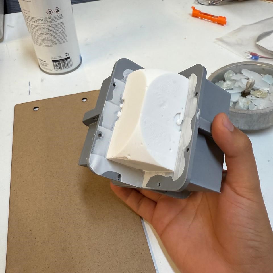
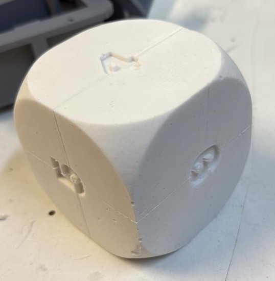
I waited until Monday to clean the mold and see the result. It was a bit hard to unmold the die, but it came out in a single piece.
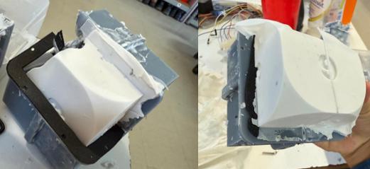
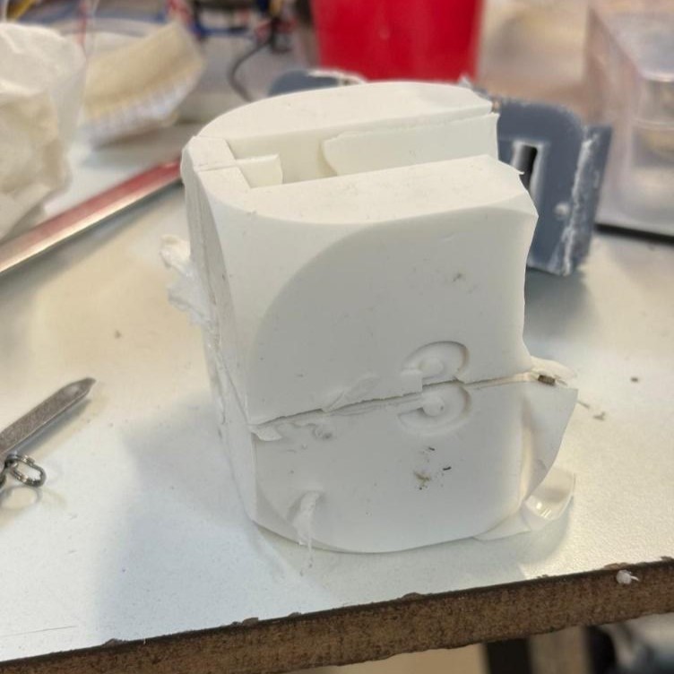
I knew I was on the right track since the general shape of the die was looking great, but I had to make some modifications to the mold to pour the silicone easily and unmold it without breaking it. I made the “Bolting Flanges” thicker and separated the holes a bit more so I could fit some nuts on the other side of the screw to get the mold parts closer and eliminate the gap I had on all faces.
Instead of a hole, I made a fifth piece to work as a cover for the mold, and to be easily removable.
I repeated the slicing process, printed them, washed them and cured them. I cut new foam parts, but I glued them into the mold so this time they would keep in place. Now I was able to add nuts to keep the parts together and have a narrower gap between them.
Once I poured the silicone inside the mold, I used a vacuum chamber to extract all the bubbles inside. The machine I used was a Kaya Vacuum Casting Machine.
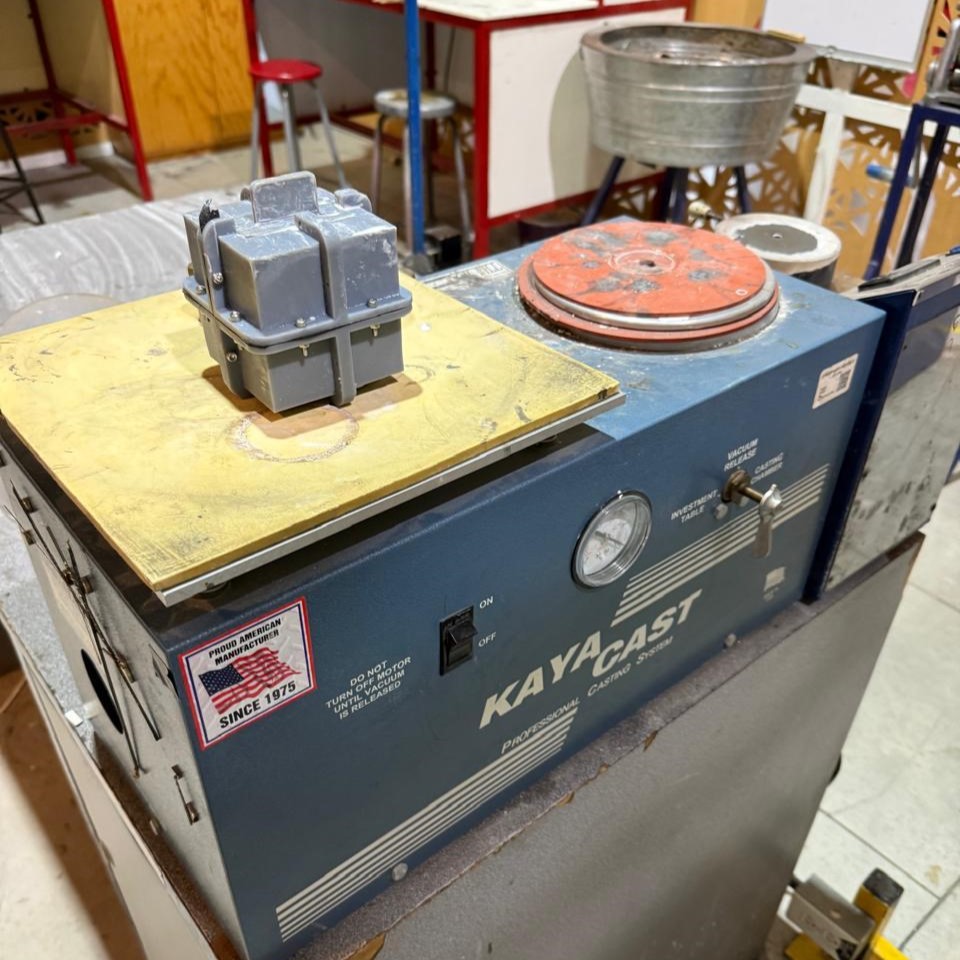
The machine is easy to use; just turn it on, put the cover on, move the handle from Vacuum Release to Investment Table, and watch the pressure go down.
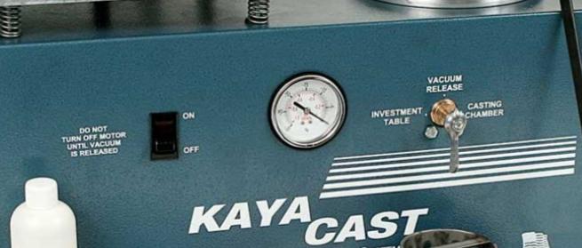
I had to be careful, because when the vacuum reached a certain pressure, the silicone started coming out of the mold, so I had to release the vacuum and repeat the process several times to get as many bubbles as possible.
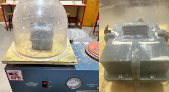
I waited a hole day to let the silicone harden and opened my mold to see the result:
Summary
I learned how to design a die and a mold for it. I also learned how to use a resin printer and how to slice the files for it. I had some problems with the mold, but the modifications I made helped me get a good result. I am happy with the final product, and I can now use it for my final project.