For week 12 I programed our CNC which you can find here.
I first tried to make the code interpret G-codes using the Arduino IDE. So, I looked at G-code commands to understand them and see how to interpret them. The following two websites were useful for that:
https://marlinfw.org/meta/gcode/
https://howtomechatronics.com/tutorials/g-code-explained-list-of-most-important-g-code-commands/
I also made a Python script to send each line from a file containing the code. I encountered some issues, like the data being sent all at once or the motors moving too much.
After doing some research on how I could send G-codes to my machine, I found that GRBL was used for Arduino and ESP32 shields, and connecting them to UGS. To keep things simple, I decided to use a XIAO ESP32 C3. It was supposed to be as simple as downloading a zip file from this website: https://github.com/bdring/Grbl_Esp32. But an error occurred every time I tried to compile the code on the Arduino IDE, probably because the library wasn´t specifically made for this board.
I also tried using VS Code and Platform IO, but experienced some troubles too. I asked Chat GPT for help, hoping it could give me an easy fix, but every time I solved an issue, I got another one. After a while, it suggested making my own library, which helped me to make a “barebones” version of GRBL. To build the library, I created a new project inside VS Code with the Platform IO extension.
I tested the first version that it gave me, but it had some trouble connecting with UGS since the code had to send “ok” after receiving a command.
Error example:
*** Fetching device state
>>> $G
[G90 G21 G17 G94 G54]
ok
*** Connected to GRBL 1.1h
>>> G90
An error was detected while sending '$G': error: Unsupported command. Streaming has been paused.
>>> G0
An error was detected while sending 'G90': error: Unsupported command. Streaming has been paused.
After adding the “ok” response and the support for most of the commands UGS uses, I was able to successfully connect and send a G-code to the board.
        void protocol_loop() {
            if (Serial.available()) {
              String line = Serial.readStringUntil('\n');
              line.trim();
              line.toUpperCase();  // Normalize case for command parsing

              if (line.length() == 0) {
                Serial.println("ok");
                return;
              }

              if (line == "?") {
                report_status();
              } else if (line == "$I") {
                Serial.println("[VER:1.1h:Barebones]");
                Serial.println("[OPT:VN]");
                Serial.println("ok");
              } else if (line == "$G") {
                Serial.println("[G90 G21 G17 G94 G54]");
                Serial.println("ok");
              } else if (line == "$$") {
                Serial.println("$0=10");
                Serial.println("$1=25");
                Serial.println("$100=240.0");
                Serial.println("$101=340.0");
                Serial.println("$102=100.0");
                Serial.println("$110=1000.0");
                Serial.println("$111=1000.0");
                Serial.println("$112=500.0");
                Serial.println("ok");
              } else if (line == "$X" || line == "$H") {
                Serial.println("ok");
              } else if (line == "G28") {
                motion_go_home();
                Serial.println("ok");
              } else {
                float x = NAN, y = NAN, z = NAN, f = -1;
                bool has_g90 = false, has_g91 = false, has_motion = false;

                char buffer[line.length() + 1];
                strncpy(buffer, line.c_str(), sizeof(buffer));
                buffer[sizeof(buffer) - 1] = '\0';
                char* ptr = buffer;

                while (*ptr) {
                  if (*ptr == 'G') {
                    ptr++;
                    long gcode = strtol(ptr, &ptr, 10);
                    switch (gcode) {
                      case 0:
                      case 1: has_motion = true; break;
                      case 90: has_g90 = true; break;
                      case 91: has_g91 = true; break;
                    }
                  } else if (*ptr == 'X') {
                    ptr++;
                    x = strtof(ptr, &ptr);
                  } else if (*ptr == 'Y') {
                    ptr++;
                    y = strtof(ptr, &ptr);
                  } else if (*ptr == 'Z') {
                    ptr++;
                    z = strtof(ptr, &ptr);
                  } else if (*ptr == 'F') {
                    ptr++;
                    f = strtof(ptr, &ptr);
                  } else {
                    ptr++;
                  }
                }

                if (has_g90) {
                  motion_set_absolute_mode(true);
                  Serial.println("ok");
                } else if (has_g91) {
                  motion_set_absolute_mode(false);
                  Serial.println("ok");
                } else if (has_motion) {
                  motion_execute_move(x, y, z, f);
                  Serial.println("ok");
                } else {
                  Serial.println("error: Unsupported command");
                }
              }
            }
          }
I converted the steps the motors could do to millimeters. To have accurate motion and scaling. To do so, I calculated that the motors needed to move 200 steps to complete a full turn. For both the X and Y axes, we used a band with a pulley whose radius is 14mm.
steps_per_mm = 200.0 / (PI * 14.0) ≈ 4.55
Since we didn´t add limit switches to the machine, I also needed to limit the number of steps the machine could move. For X, I set the limit to 800, and for Y, 1,000.
I decided to add four buttons to my PCB to move both axes and one extra to set the origin. So, after making the conversion from steps to millimeters, I added support for the buttons in the code:
        void manual_control_loop() {
            static unsigned long last_move = 0;
            const unsigned long debounce_time = 200;  // ms

            if (millis() - last_move < debounce_time) return;

            if (digitalRead(BTN_X_POS) == LOW) {
              Serial.println("🔼 X+ Pressed");
              digitalWrite(X_DIR_PIN, HIGH);
              for (int i = 0; i < 10; i++) {
                digitalWrite(X_STEP_PIN, HIGH);
                delayMicroseconds(1000);
                digitalWrite(X_STEP_PIN, LOW);
                delayMicroseconds(1000);
              }
              last_move = millis();
            }

            if (digitalRead(BTN_X_NEG) == LOW) {
              Serial.println("🔽 X- Pressed");
              digitalWrite(X_DIR_PIN, LOW);
              for (int i = 0; i < 10; i++) {
                digitalWrite(X_STEP_PIN, HIGH);
                delayMicroseconds(1000);
                digitalWrite(X_STEP_PIN, LOW);
                delayMicroseconds(1000);
              }
              last_move = millis();
            }

            if (digitalRead(BTN_Y_POS) == LOW) {
              Serial.println("➡️  Y+ Pressed");
              digitalWrite(Y_DIR_PIN, HIGH);
              for (int i = 0; i < 10; i++) {
                digitalWrite(Y_STEP_PIN, HIGH);
                delayMicroseconds(1000);
                digitalWrite(Y_STEP_PIN, LOW);
                delayMicroseconds(1000);
              }
              last_move = millis();
            }

            if (digitalRead(BTN_Y_NEG) == LOW) {
              Serial.println("⬅️  Y- Pressed");
              digitalWrite(Y_DIR_PIN, LOW);
              for (int i = 0; i < 10; i++) {
                digitalWrite(Y_STEP_PIN, HIGH);
                delayMicroseconds(1000);
                digitalWrite(Y_STEP_PIN, LOW);
                delayMicroseconds(1000);
              }
              last_move = millis();
            }

            if (digitalRead(BTN_SET_ORIGIN) == LOW) {
              Serial.println("🔄 Origin set (manual)");
              current_position[X_AXIS] = 0.0;
              current_position[Y_AXIS] = 0.0;
              last_move = millis();
            }
          }
I also added a function to set the origin. I had to make some changes to the code since the machine was moving in the opposite direction. I had to change the direction of the motors, and I also had to change the way I set the origin. I used a button to set it, but I had to make sure that when I pressed it, the machine was at 0,0. So, I made a function that sets the origin when the button is pressed.
The code for setting the origin is as follows:
void set_origin() {
    Serial.println("Setting origin...");
    current_position[X_AXIS] = 0.0;
    current_position[Y_AXIS] = 0.0;
    current_position[Z_AXIS] = 0.0;
    Serial.println("Origin set.");
}
After some trial and error, I figured out that in this position, the origin should be set every time to avoid collisions. On the X axis near the motor, and the Y axis away from the motor.
For the Z axis, we used a servomotor to have an up/down functionality. Initially, I programmed it to move with G0 Z0 and G0 Z10, but I had some trouble because if I sent G0 Z10 more than once, for example, the program would assume that the motor was in Z20, and I had to type Z-20 so it could return to Z0. This happened because it had the same programming as the other two axes. We used a 360° servomotor, so I tried to map the full movement, but I used the ESP32 servomotor library, so it could only move from 0° to 180°, but I solved the command problem.
void z_move_to(float z_target) {
// Map from 0-10 → 0-360 degrees
float clamped = constrain(z_target, 0.0, 10.0);  // limits between 0 and 10
int angle = map(clamped * 100, 0, 1000, 0, 360);

Serial.printf("↕ Moving Z (servo) to angle: %d°\n", angle);
z_servo.write(angle);
delay(500);  // Small delay to complete the movement
}
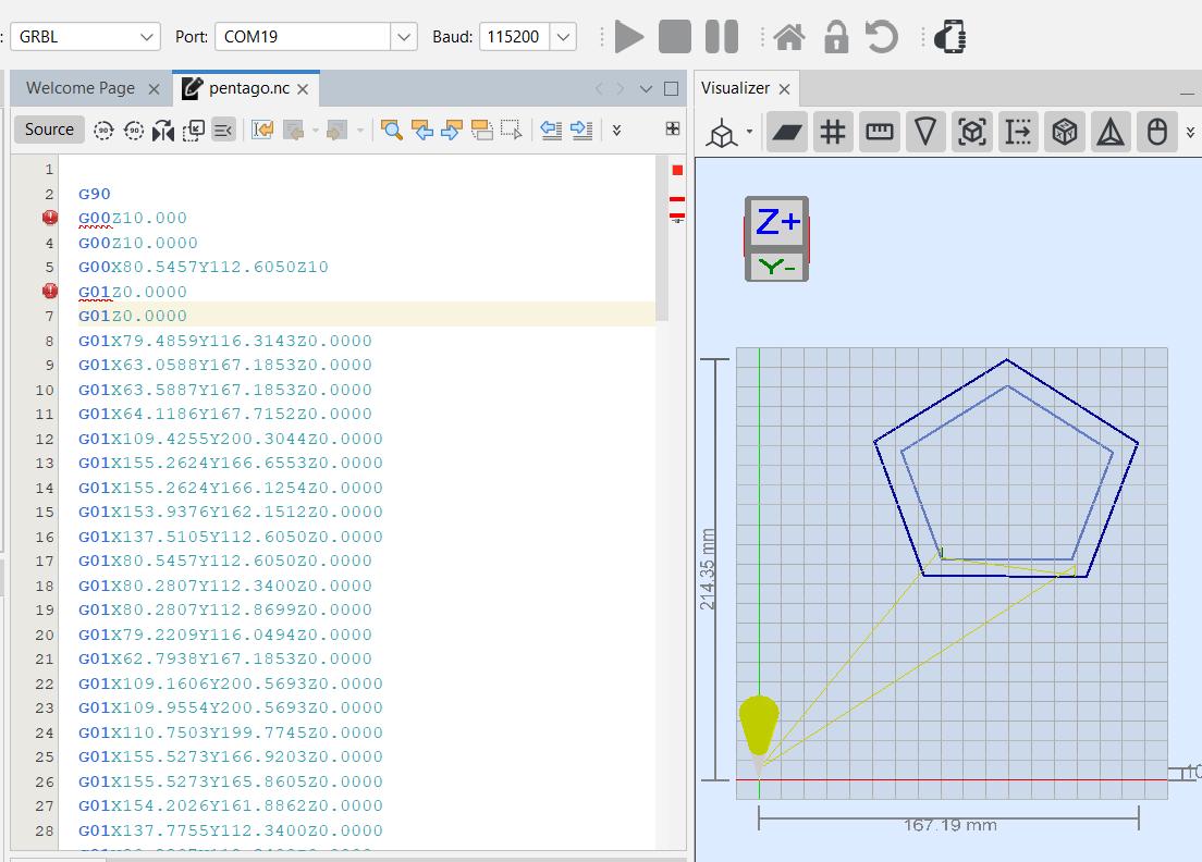
With all these changes, I was ready to upload the first full G-code and see if everything worked correctly. I opened a text file containing a G-code to draw a pentagon on UGS. I got the code by importing a PNG image into mods, I set the origin, and hit the play button. But an error occurred, I couldn´t tell right away what it was, since I was able to send data from the console window.
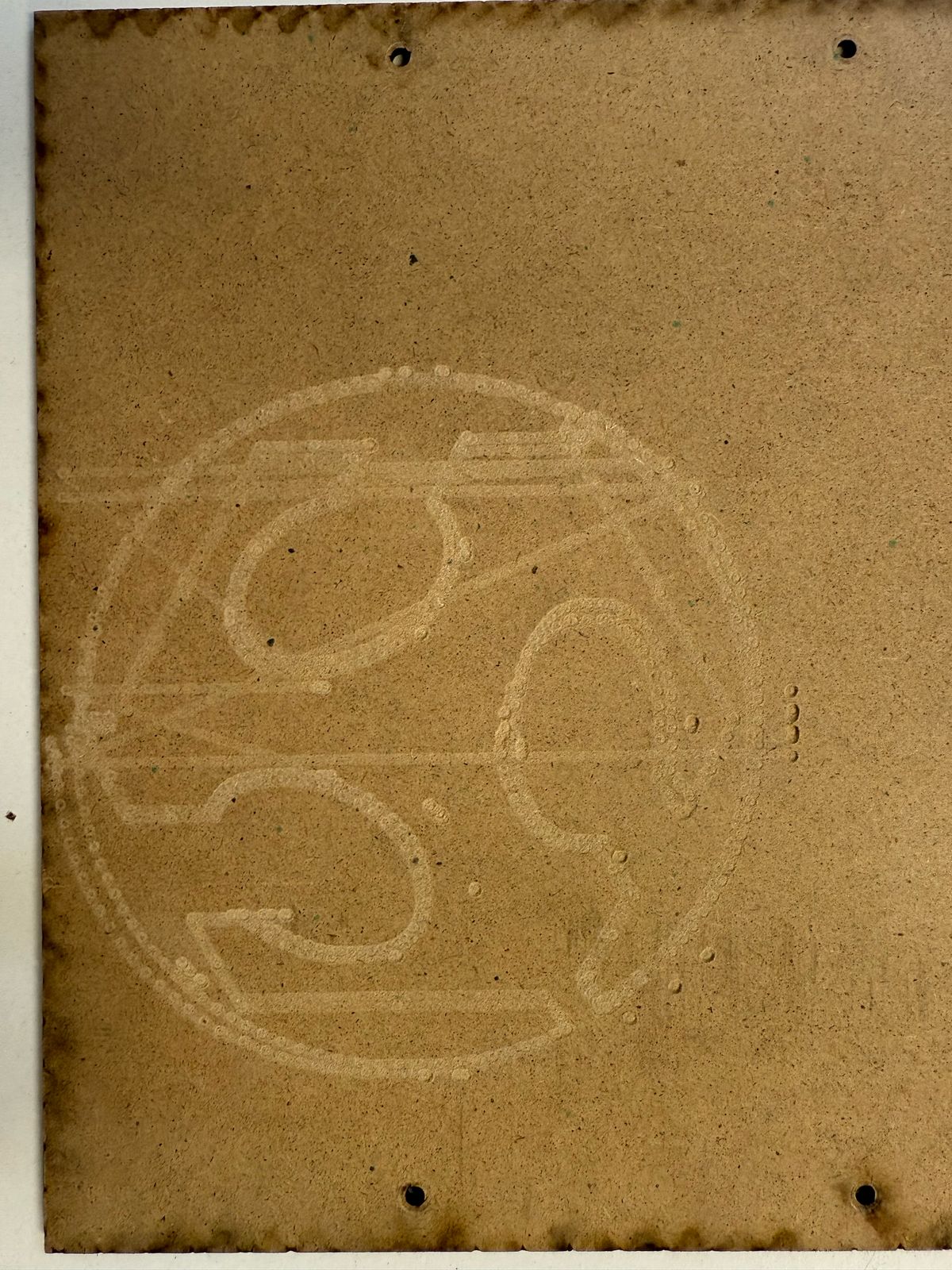
At the time of the test, we didn´t have the servomotor attached to the CNC, so I taped a pen to test functionality. I tried pasting the whole code into that window. And saw the machine moving. Here´s what it drew:
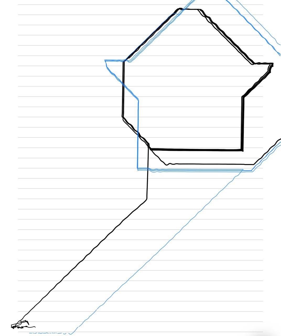
I clearly had to make some changes to the code since this wasn´t completely right. This is what it should look like:
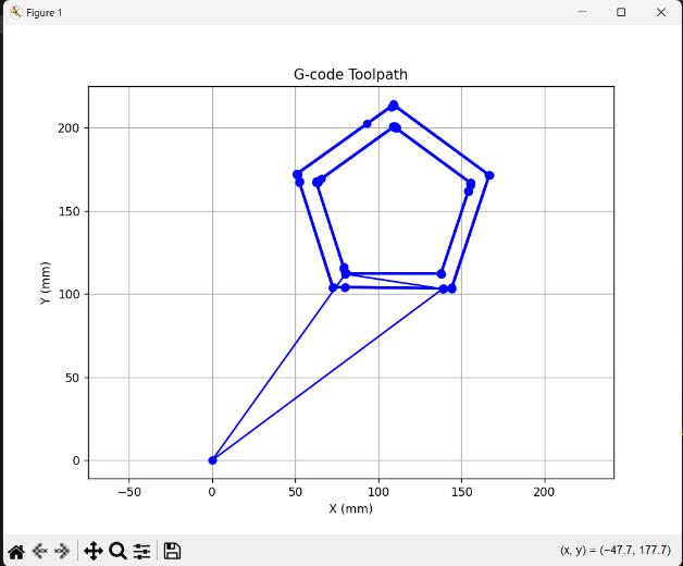
After making some changes to the code, I got the desired form:
I tried with a simplified version of the pentagon to clearly see what was wrong, I realized that the problem had to do with the speed the stepper motors were moving. They moved at the same time, so one could finish first, making the wrong movement. I asked Chat GPT to help me change the code´s logic to move the stepper motors correctly. Here´s the part I changed to move the motors correctly:
            // Calculate step deltas float delta_x = target[X_AXIS] - current_position[X_AXIS]; float delta_y = target[Y_AXIS] - current_position[Y_AXIS];

            long steps_x = abs(MM_TO_STEPS_X(delta_x)); long steps_y = abs(MM_TO_STEPS_Y(delta_y));

            // Direction int dir_x = (delta_x >= 0) ? HIGH : LOW; int dir_y = (delta_y >= 0) ? HIGH : LOW; digitalWrite(dir_pin[X_AXIS], dir_x); digitalWrite(dir_pin[Y_AXIS], dir_y);

            // Total distance using Pythagoras (Euclidean distance) float distance_mm = sqrt(delta_x * delta_x + delta_y * delta_y);

            // Feedrate: convert mm/min to time per step if (f > 0 && distance_mm > 0) { float mm_per_step = distance_mm / max(steps_x, steps_y); step_delay_us = (60000000.0 / f) * mm_per_step; if (step_delay_us < 200) step_delay_us = 200; } else { step_delay_us = 5000; }

            long steps = max(steps_x, steps_y); long counter_x = 0; long counter_y = 0;

            unsigned long last_step_time = micros(); for (long i = 0; i < steps; i++) { while (micros() - last_step_time < step_delay_us); // wait last_step_time = micros();

            counter_x += steps_x;
            counter_y += steps_y;

            if (counter_x >= steps) {
                digitalWrite(step_pin[X_AXIS], HIGH);
                delayMicroseconds(10);
                digitalWrite(step_pin[X_AXIS], LOW);
                counter_x -= steps;
            }

            if (counter_y >= steps) {
                digitalWrite(step_pin[Y_AXIS], HIGH);
                delayMicroseconds(10);
                digitalWrite(step_pin[Y_AXIS], LOW);
                counter_y -= steps;
            }


            }
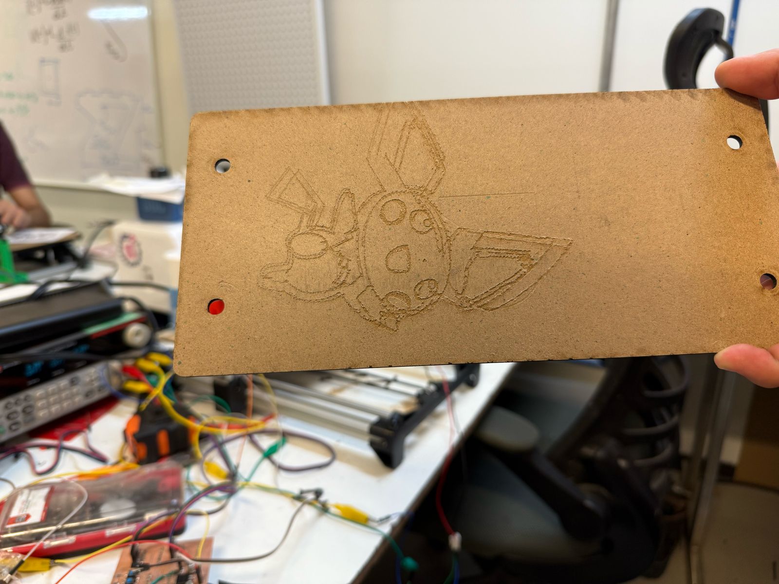
After applying these changes, the CNC successfully drew a pentagon. We tried with different g codes, and they worked.
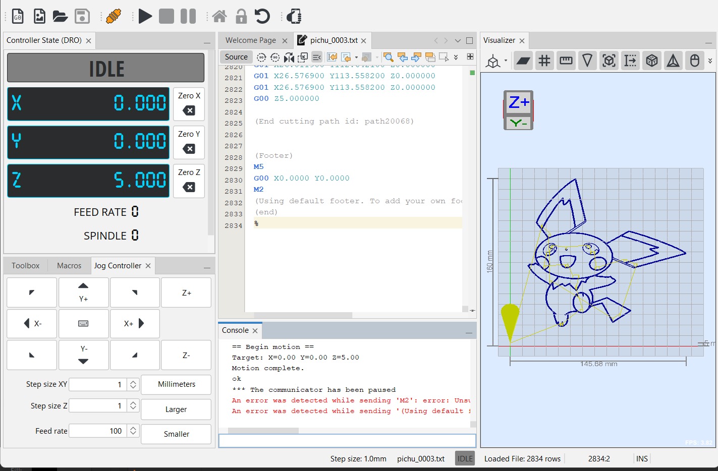
UGS interface:
Here´s the zip file containing the final library created:
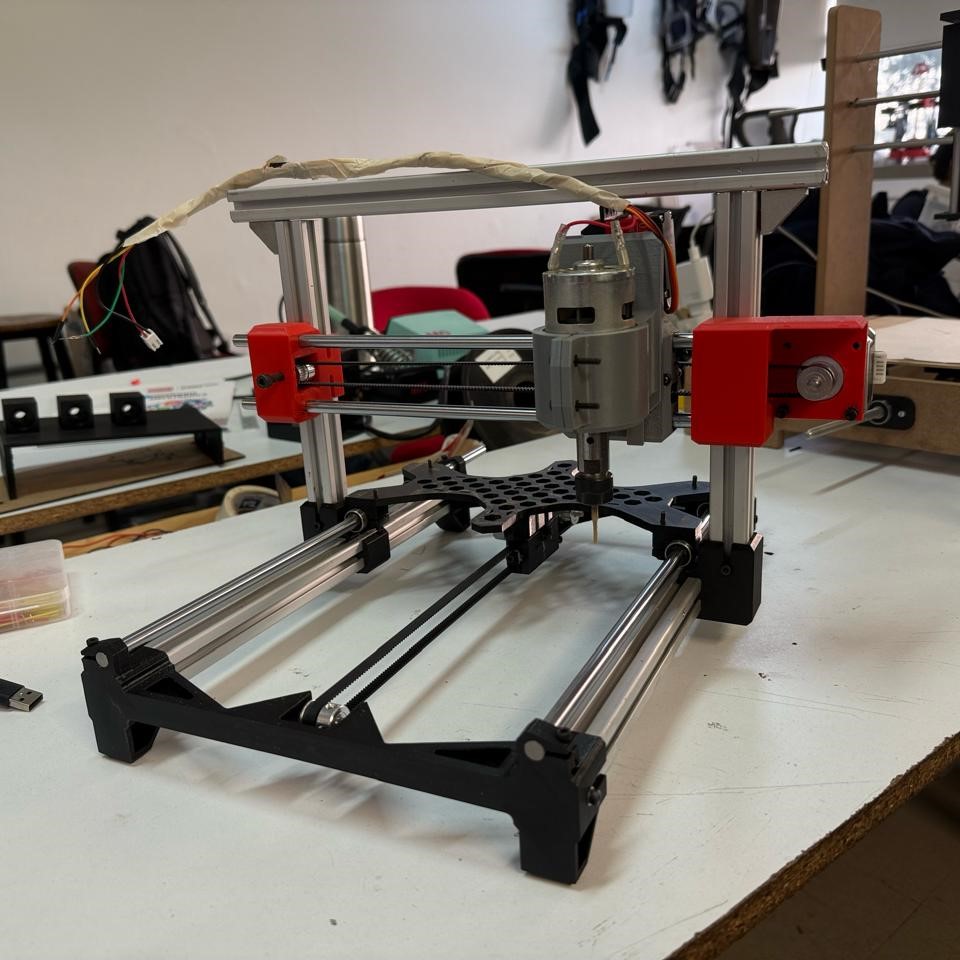
Here´s our CNC:
Summary
Maybe it would´ve been a better option to polish the first code I created to interpret G-codes, but this was the path that led to the CNC fully operating. I made bigger improvements following this path than the other ones. It doesn´t fully support UGS, since I can´t control the machine with the buttons inside the UGS interface, and I didn´t fix the error it gave when I tried to run a file. Nonetheless, UGS was a way to send the code from the console, and it verified each action automatically before sending the next one. It also provided an interface where I could have a preview of the G-code and live axes position. Although I made this library considering the XIAO ESP32 C3, it can be used with other boards; the only things that need to be changed are the servo library, pin configuration, and the platform.ini file, depending on the board.