7. Computer Controlled Machining
What is Computer Controlled Machining?
Computer-controlled machines are used to cut, mill, drill, and shape materials. They are controlled by a computer that reads a set of instructions and moves the machine's cutting tool to the desired location. Used in a wide range of industries, including manufacturing, aerospace, automotive, and construction, to make products, from simple parts to complex components. It is a versatile and precise method of manufacturing that can produce high-quality parts with tight tolerances.
Wooden Resting Chair Design
I love to read before bed, but I don't like to sit on my bed, so this week I designed a wooden resting chair where I could sit comfortably to read. I used SOLIDWORKS to design all the pieces and imported the dxf files into VCarve to generate the g-code. We also did a group assignment which you can find here.
The plywood we were given was 2400x1200mm and 15mm thick, so I had to make all the parts to fit in that area. I used Procreate to make a sketch of my chair.
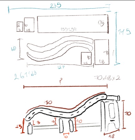
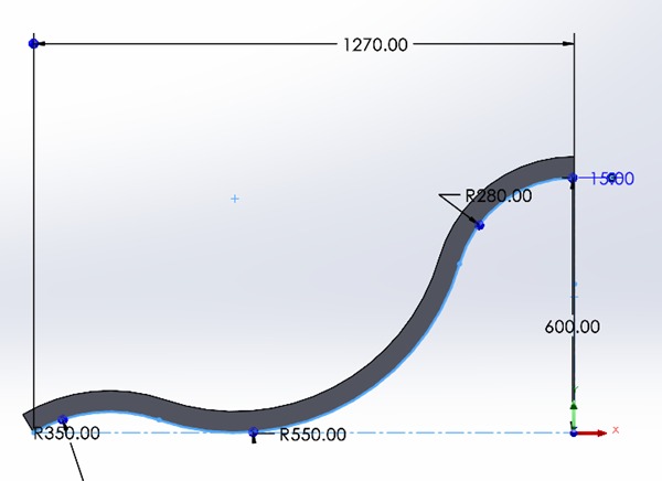
After having a general idea of the pieces and sizes I needed, I designed each piece on SOLIDWORKS. I started by defining an "s" curve as the main shape of the chair.
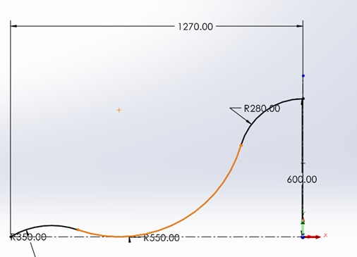
I made three tangent circles with different radiuses. I'm 1.7 meters tall, so I measured the distance between my neck and my waist, my knees to my waist, and my knees to my foot so I could give each circle the correct value to be comfortable.
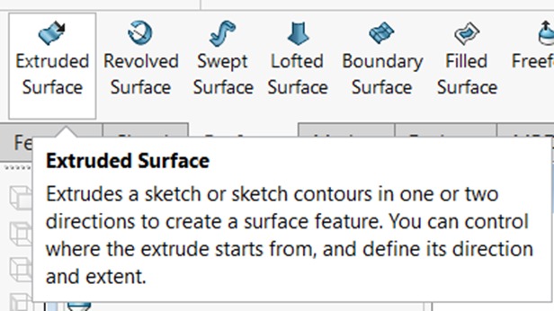
Once I had the curve, I used the "Extruded Surface" tool to make it a surface.
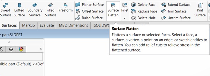
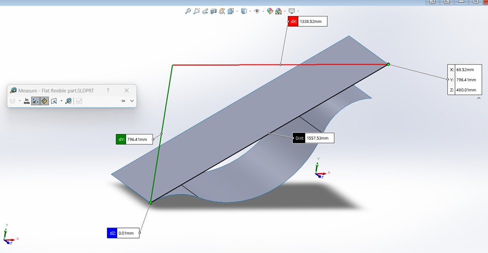
I was going to cut plywood, which is flat, so I needed to know the curve's length. To do so, I used the "Surface Flatten" tool to flatten the surface, and with the measure tool, I obtained its length.
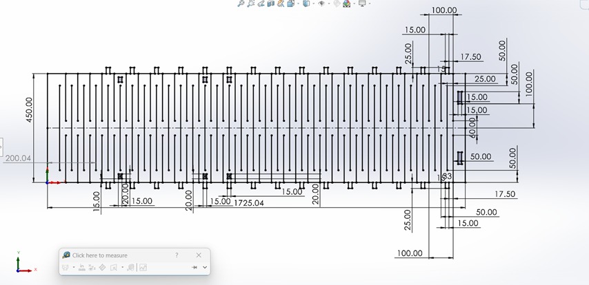
I designed this piece to be flexible, so I had to add some joints and holes to assemble it in its final shape.
I created two curved parts for each side.
I had to make the holes to assemble it with the flexible part, to avoid making them manually, I thickened the surface with the joints and made an assembly on SOLIDWORKS.
To make the flat sketch follow the curve I made, I had to add that surface:
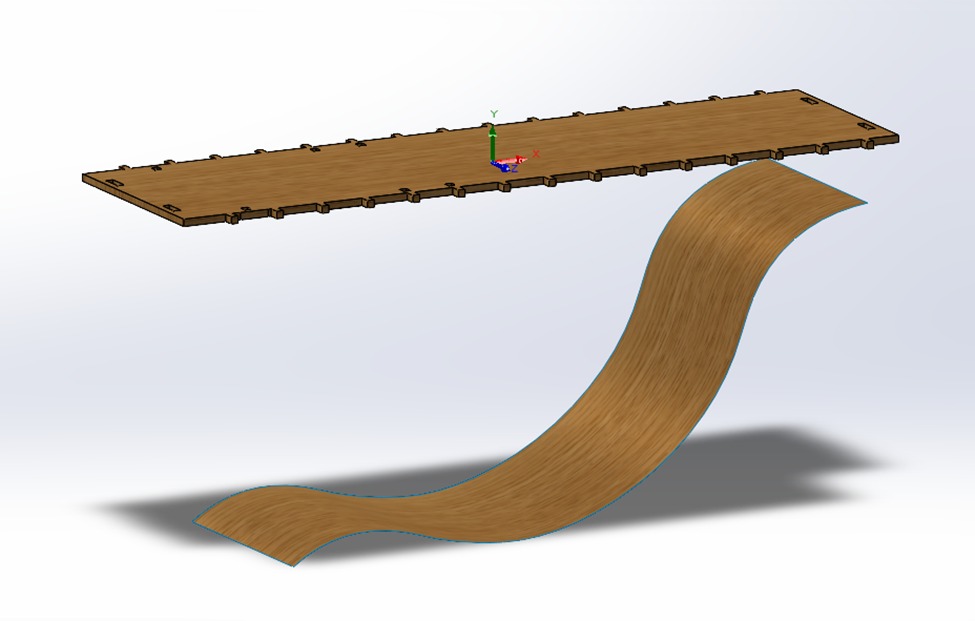
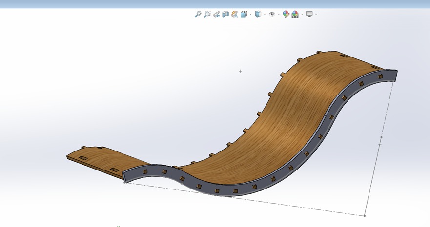
Then with the "Deform" tool, I changed its shape:
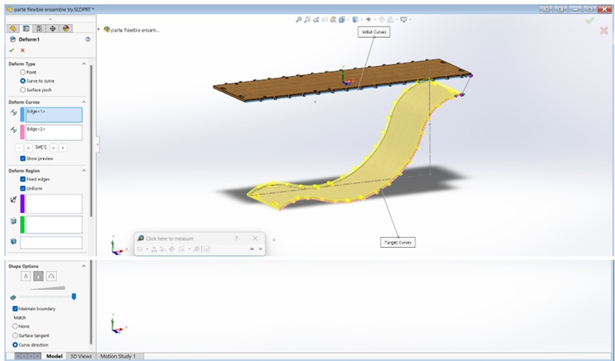
I opened an assembly document and added both parts:
I only made the side faces coincident and then moved the parts until each joint crossed almost in the middle of the side part. I saved the assembly as a single body.
I opened the new part and then I used the "Combine" tool to make the holes by subtracting both pieces.
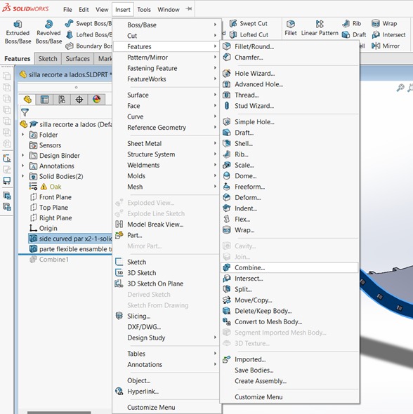
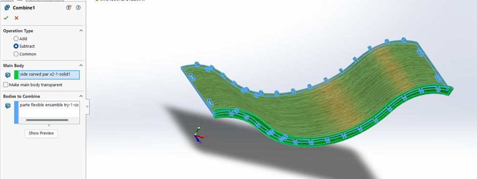
The part that I obtained had the holes with the correct spacing:
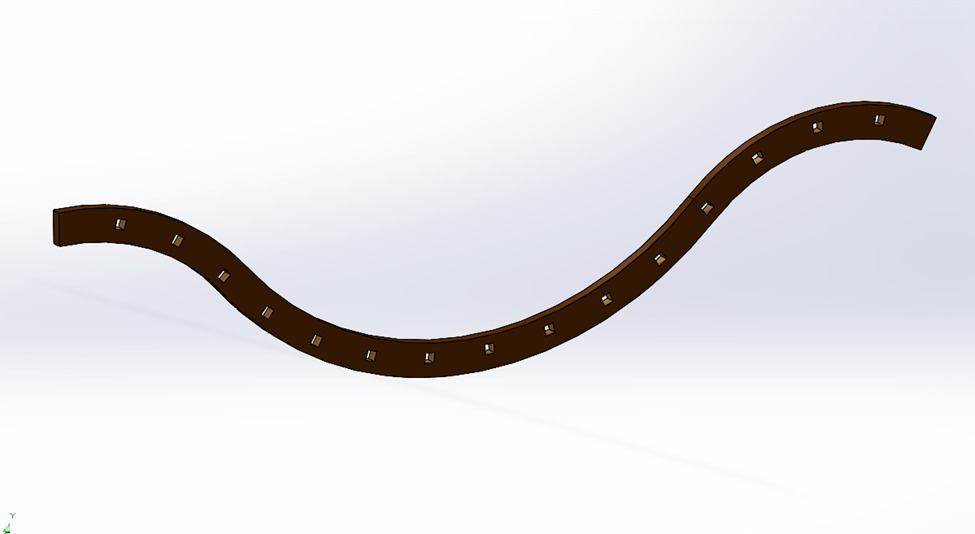
Bottom Supports
I designed the bottom supports with three different lengths:
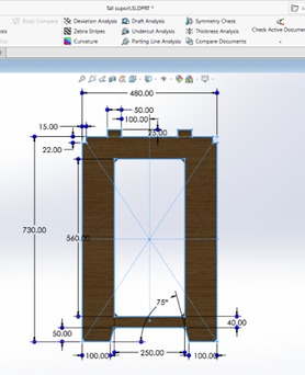
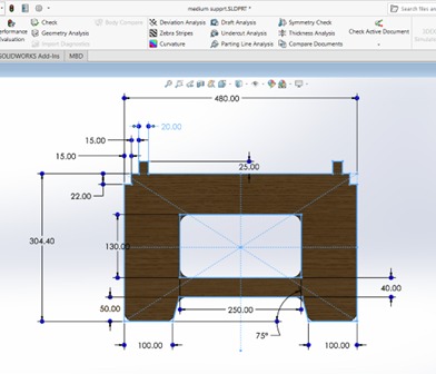
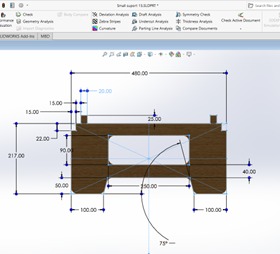
To get the right height for each support, I made an assembly where I put all the parts together. I made a "floor" to make sure all the parts touched the ground evenly.
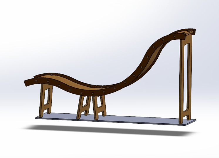
The assembly also helped me to see how the final result would look like:
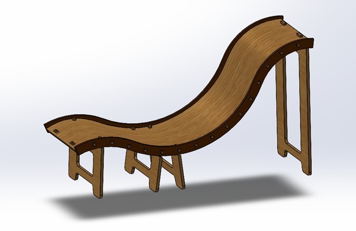
Exporting to VCarve
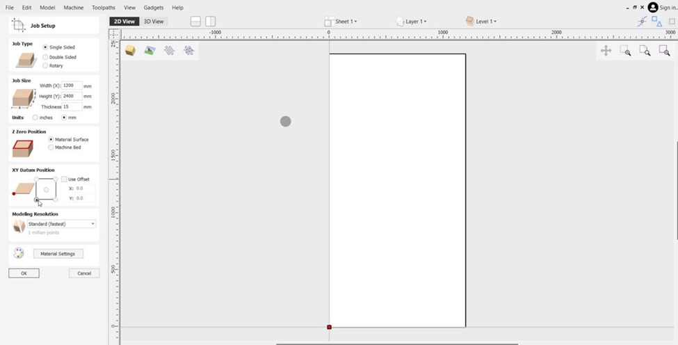
Then I saved each part as dxf to import them into VCarve. I opened a new project and selected the following parameters:
Then I imported the dxf files:
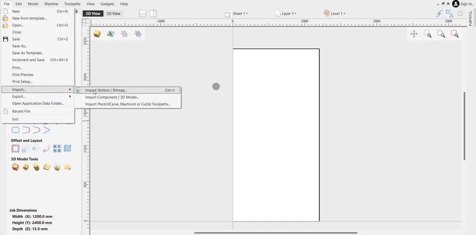
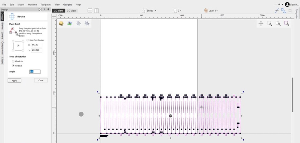
You can move or rotate the imported file by pressing "m" or "r" respectively.
Although it is a single file, it has multiple vectors, so I had to combine them by using the "join open vectors" tool.
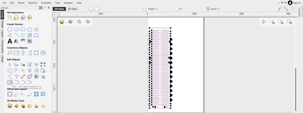
I took these steps with every part, making sure everything fit.
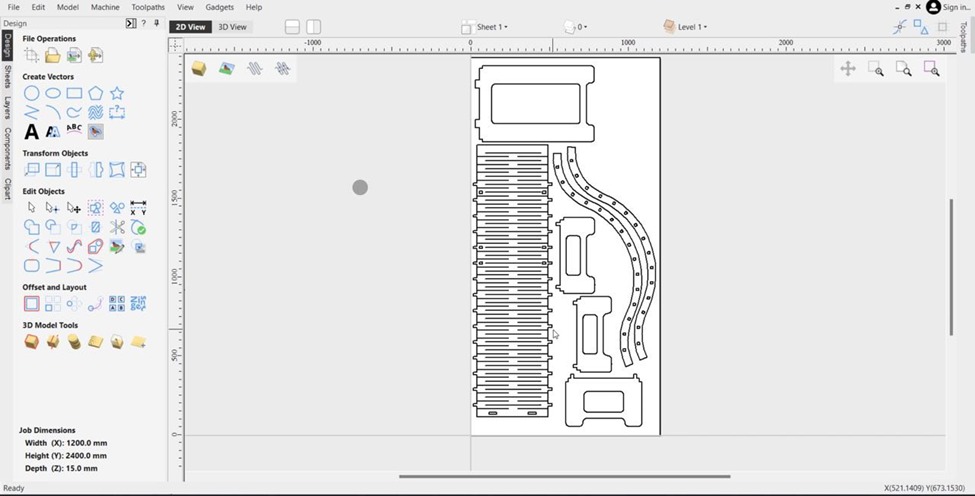
Once I had all the parts, it was time to make some fillets on the corners I needed:
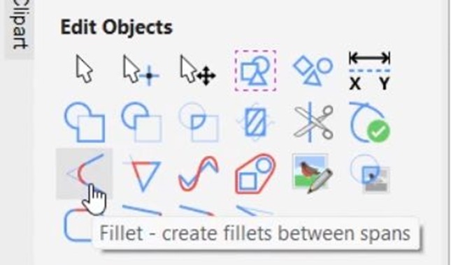
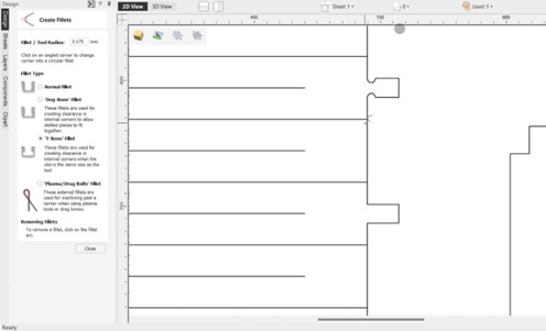
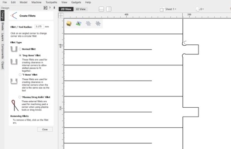
I used the dog bone fillet because it didn't cut too much into the joints.
I added the fillets to all the inner corners of my pieces. And then I selected "Profile Toolpath" on the right side of the screen.
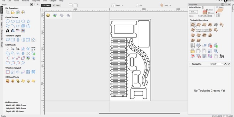
I chose the cut depth and configured the tool I was going to use:
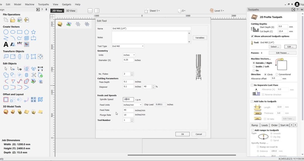
I used a two flutes 1/4" mill since on our group assignment we consulted the feed and speed needed for this tool and it was available to use at the time. I set the Spindle Speed to 18,000 rpm, a Feed Rate of 40 inches/min to go a bit slower just to be safe, it was my first time using the machine so I wanted to make sure I got it right on the first try.
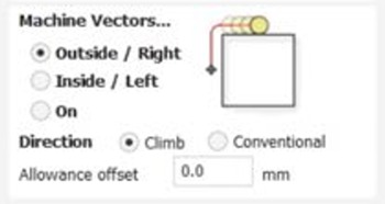
I added some tabs to keep the pieces in place while the machine is cutting and to avoid any material from flying. First, I selected all the vectors that I was going to cut from the outside and then changed the tab's dimensions.
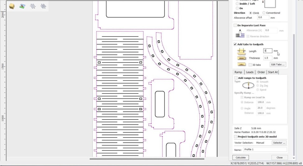
Then I clicked on "Edit tabs" to place the tabs around the pieces:
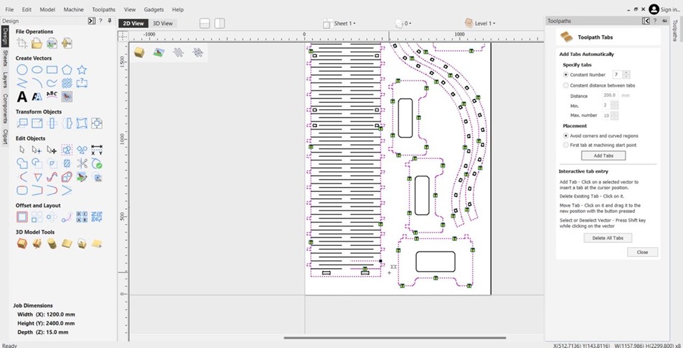
I changed the constant number to seven to add more tabs and then I checked that the tabs were correctly placed.
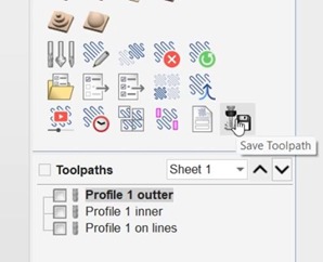
Once I finished configuring the toolpath, I scrolled down and clicked "Calculate". Once it finished, a preview window appeared. After checking everything was correct, I created two extra tool paths. The Inside path for the parts that would become a hole and the in path for the flexible part.
After I had all the paths, I clicked on "Save toolpath", then chose the post processor for the machine I was going to use and then saved the toolpath into a removable drive.
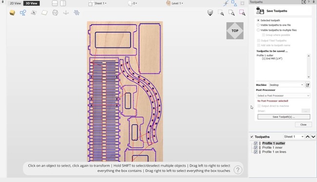
I copied the file to the Router, set the origin, and started cutting.
I used this controller to configure the machine:
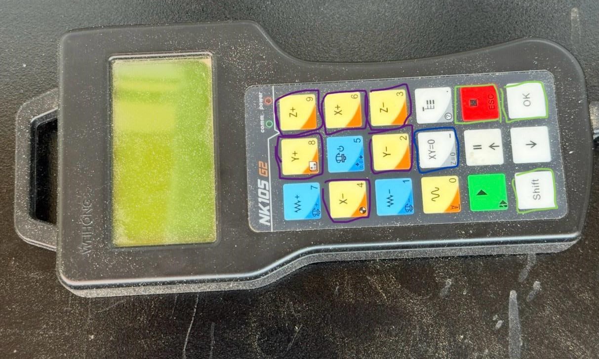
To set the origin I used the XY=0 button (blue square), to move the CNC I used the axis buttons (purple squares), and to navigate the menu I used the other buttons (green squares). The red button is also the emergency stop button.
I cleaned the wood chips once the machine finished.
After cutting all the pieces, I sanded them to make them smooth.
Finally I assembled it.
Here´s the result:
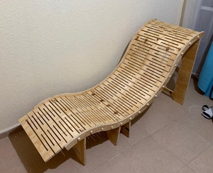
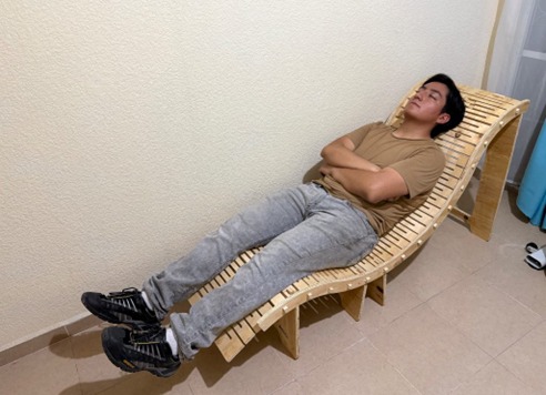
It turned out very comfy, I will be using it every day to read before bed.
Summary
This week was labour intensive, the machine took over two hours to cut all the parts, it took me over three hours to sand them and another two hours to assemble them. I made the holes and joints to have the same dimensions so it was a bit hard to assemble them. I had to use a hammer to make them fit. I learned that I could design a flexible piece, even though it was a thicker material, by using the same technique I used to make my roller coaster. By using complex tools on SOLIDWORKS, I could make the parts fit perfectly and avoid issues while assembling it. I also learned how to use VCarve, unfortunately there aren´t many computers with the software available at the lab, so I tried to download the free trial version on my computer, I generated the tool paths only to find out I couldn´t save the g-code. The next day I went to the lab to generate the g-code on a computer with the software, but the VCarve version was different so I had to start over, when I finished the tool paths I couldn´t save them because the computer didn´t had the post processor for the machine I was going to use so I had to use a different computer, fortunately I only had to open the VCarve project on the computer with the post processor. After all the isues I had, I was surprised how comfortable the chair turned out to be, I thought it would be too hard, but it was perfect. I will be using it every day and maybe even make another one for my living room.
