4. Embeded Programming
Embedded programming, refers to the development of software for embedded systems. These systems are designed to perform specific tasks within larger mechanical or electrical systems, unlike general-purpose computers, which are designed to handle a wide range of tasks. There are several Programming Languages and development environments (IDEs), all of them with their own capabilities and functionalities.
This week we started programming, for our group assignment we compared different programming languages and the available controllers in our Fab, you can check it I also did a group assignment to test the 3D printer and some research for this week you can find it here.
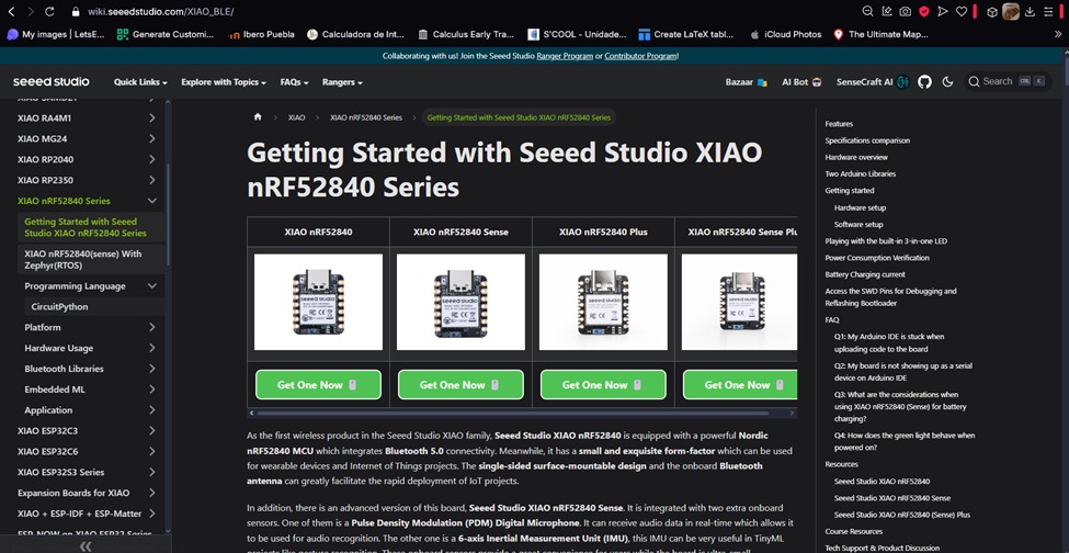
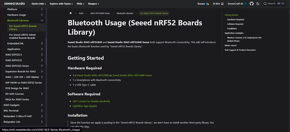
For my final project, I will be using the built-in accelerometer from the XIAO nRF52840 (sense), so I decided to compare two ways of reading the sensor’s information and sending it via Bluetooth. I will be using CircuitPython and Arduino IDE.I started by doing some research about the XIAO nRF52840 (sense) to see all its available features. I had previously used this board to make a small project, the manufacturer has a webpage that explains how to use all the features available for the board.
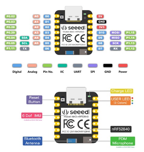
Here’s the pinout of the board I’ll be using:
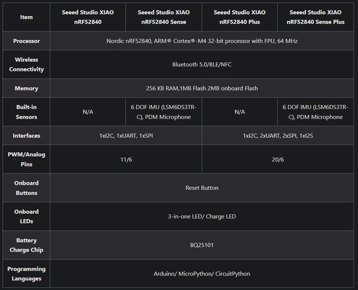
Here’s a table for all the sensors and built-in features:
CIRCUITPYTHON
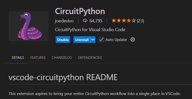
I used Visual Studio Code with the CircuitPython extension. You can see all the steps to install CircuitPython on the XIAO here.
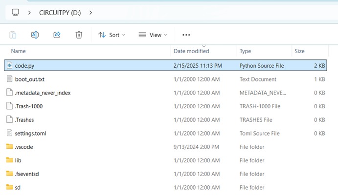
After the installation, you will see that one of the files inside the board is called “code.py” Every time you make a code you need to paste it in here and save it (you can’t save another file to program the XIAO). You can add the libraries you need inside the “lib” folder.
I’ve never used Bluetooth from the nRF52840 (sense), so I browsed the web until I found some examples to use the CircuitPython libraries, here’s the link to download the libraries and examples I used. This code gave me an idea of how to make my code:
# SPDX-FileCopyrightText: 2021 ladyada for Adafruit Industries
# SPDX-License-Identifier: MIT

# Basic structure example for using the BLE Connect Controller sensors
# To use, start this program, and start the Adafruit Bluefruit LE Connect app.
# Connect, and then select Controller and enable the sensors

# Import required libraries for BLE communication and packet handling
from adafruit_ble import BLERadio
from adafruit_ble.advertising.standard import ProvideServicesAdvertisement
from adafruit_ble.services.nordic import UARTService
from adafruit_bluefruit_connect.packet import Packet

# Import specific packet classes that define the types of sensor data we expect
from adafruit_bluefruit_connect.accelerometer_packet import AccelerometerPacket
from adafruit_bluefruit_connect.gyro_packet import GyroPacket
from adafruit_bluefruit_connect.location_packet import LocationPacket
from adafruit_bluefruit_connect.magnetometer_packet import MagnetometerPacket
from adafruit_bluefruit_connect.quaternion_packet import QuaternionPacket

# Create an instance of the BLERadio class to manage BLE communication
ble = BLERadio()

# Create a UART service for communication between devices over BLE
uart_server = UARTService()

# Set up the advertisement for the BLE service, so that devices can discover and connect
advertisement = ProvideServicesAdvertisement(uart_server)

# Start an infinite loop to continuously check for BLE connections and handle sensor data
while True:
	print("WAITING...")
	# Begin advertising the BLE service so that a device can connect
	ble.start_advertising(advertisement)

	# Keep waiting until a device connects
	while not ble.connected:
		pass  # Do nothing while waiting for a connection

	# Once connected, stop advertising because the connection has been made
	ble.stop_advertising()
	print("CONNECTED")

	# Start a loop to read incoming packets from the connected BLE device
	while ble.connected:
		# Try to read a packet from the UART service
		try:
			packet = Packet.from_stream(uart_server)
		except ValueError:
			# If the packet is invalid, continue and wait for the next one
			continue

		# Check if the packet is an accelerometer data packet and print its values
		if isinstance(packet, AccelerometerPacket):
			print("Accelerometer:", packet.x, packet.y, packet.z)

		# Check if the packet is a gyro data packet and print its values
		if isinstance(packet, GyroPacket):
			print("Gyro:", packet.x, packet.y, packet.z)

		# Check if the packet is a location data packet and print its values
		if isinstance(packet, LocationPacket):
			print("Location:", packet.latitude, packet.longitude, packet.altitude)

		# Check if the packet is a magnetometer data packet and print its values
		if isinstance(packet, MagnetometerPacket):
			print("Magnetometer", packet.x, packet.y, packet.z)

		# Check if the packet is a quaternion data packet and print its values
		if isinstance(packet, QuaternionPacket):
			print("Quaternion:", packet.x, packet.y, packet.z, packet.w)

	# If the connection is lost or disconnected, exit the loop and notify the user
	print("DISCONNECTED")
You can find this example inside of the zip file exaples>bluebruitconnect. The file is named "bluebruitconnect_sensors.py"
I combined it with a code previously made to read the accelerometer data:
# Import necessary libraries
import time  # For time delays
import board  # For pin definitions
import busio  # For I2C communication
import digitalio  # For digital input/output
from adafruit_lsm6ds.lsm6ds3 import LSM6DS3  # For accelerometer and gyroscope sensor
import pwmio  # For controlling PWM (Pulse Width Modulation)
from adafruit_motor import servo  # For controlling servo motors

# Create a PWMOut object on Pin A2 for servo motor control.
# duty_cycle is set to half of the maximum value (2^15), and the frequency is 50 Hz (standard for servos).
pwm = pwmio.PWMOut(board.A2, duty_cycle=2 ** 15, frequency=50)

# Create a servo object using the PWM object. This allows control of the servo motor.
my_servo = servo.Servo(pwm)

# Define pins for three LEDs
led_pin1 = board.D7  # Pin for LED 1
led1 = digitalio.DigitalInOut(led_pin1)  # Create a DigitalInOut object for LED 1
led1.direction = digitalio.Direction.OUTPUT  # Set LED 1 as an output

led_pin2 = board.D8  # Pin for LED 2
led2 = digitalio.DigitalInOut(led_pin2)  # Create a DigitalInOut object for LED 2
led2.direction = digitalio.Direction.OUTPUT  # Set LED 2 as an output

led_pin3 = board.D9  # Pin for LED 3
led3 = digitalio.DigitalInOut(led_pin3)  # Create a DigitalInOut object for LED 3
led3.direction = digitalio.Direction.OUTPUT  # Set LED 3 as an output

# Define and power on the IMU sensor by setting the power pin to True
imu_power = digitalio.DigitalInOut(board.IMU_PWR)
imu_power.direction = digitalio.Direction.OUTPUT
imu_power.value = True  # Power on the IMU sensor
time.sleep(0.1)  # Wait for the IMU sensor to power up

# Set up I2C communication with the IMU sensor using the specified SCL and SDA pins
i2c = busio.I2C(board.IMU_SCL, board.IMU_SDA)

# Initialize the LSM6DS3 sensor (accelerometer and gyroscope) using I2C
sensor = LSM6DS3(i2c)

# Start an infinite loop to continuously read sensor data
while True:
    # Get the acceleration data (x, y, z axes) from the sensor
    acc_x, acc_y, acc_z = sensor.acceleration
    # Print the accelerometer readings (X, Y, Z)
    print(f'X:{acc_x} Y:{acc_y} Z:{acc_z}')

    time.sleep(0.1)  # Wait a little before the next reading

    # Condition for picking up an object (based on accelerometer values)
    if acc_x <= -8 and acc_y <= 2 and acc_y > -1 and acc_z <= 4:
        # Turn on LED1 to indicate "motor stopped"
        led1.value = True
        led2.value = False  # Turn off LED2 (direction indicator)
        time.sleep(0.1)

    # Condition for launching a plate upward (based on accelerometer values)
    if acc_z >= 7 and acc_x >= -3 and acc_x <= 1:
        # Turn off both LED1 and LED2 (motor stopped)
        led1.value = False
        led2.value = False
        # Set servo to angle 44 degrees (launch position)
        my_servo.angle = 44
        time.sleep(0.4)  # Wait for the servo to move to the launch position
        # Optionally, return the servo back to a neutral position (uncomment below if needed)
        # my_servo.angle = 120

    # Condition for when the plate is facing down (based on accelerometer values)
    if acc_x < 3 and acc_x > -3 and acc_z <= -5:
        # Turn off LED1 and LED2 (motor stopped)
        led1.value = False
        led2.value = False
        # Turn on LED3 to indicate "plate facing down"
        led3.value = True
        time.sleep(0.5)  # Wait for a short period

        # Gradually move the servo from 44 to 115 degrees in steps of 3 degrees
        for angle in range(44, 115, 3):
            my_servo.angle = angle  # Move the servo to the new angle
            time.sleep(0.2)  # Wait between each step to allow the servo to move

        # Optionally, return the servo to its neutral position (uncomment below if needed)
        # my_servo.angle = 120
        # time.sleep(0.1)
And here’s the final result:
		# Import necessary libraries
		import time  # For time delays
		import board  # For pin definitions
		import busio  # For I2C communication
		import digitalio  # For digital input/output
		from adafruit_lsm6ds.lsm6ds3 import LSM6DS3  # For accelerometer and gyroscope sensor
		import adafruit_ble  # For Bluetooth Low Energy (BLE) functionality
		from adafruit_ble.advertising.standard import ProvideServicesAdvertisement  # For BLE advertising
		from adafruit_ble.services.nordic import UARTService  # For BLE UART communication

		# Initialize the accelerometer (IMU sensor)
		imu_power = digitalio.DigitalInOut(board.IMU_PWR)  # Define the IMU power pin
		imu_power.direction = digitalio.Direction.OUTPUT  # Set the IMU power pin as an output
		imu_power.value = True  # Power on the IMU sensor
		time.sleep(0.1)  # Wait for the IMU sensor to power up

		# Set up I2C communication with the accelerometer using the specified SCL and SDA pins
		i2c = busio.I2C(board.IMU_SCL, board.IMU_SDA)

		# Initialize the LSM6DS3 accelerometer sensor using I2C
		sensor = LSM6DS3(i2c)

		# Initialize BLE (Bluetooth Low Energy)
		ble = adafruit_ble.BLERadio()  # Create a BLE radio object for communication
		uart_service = UARTService()  # Create a UART service for Bluetooth communication
		advertisement = ProvideServicesAdvertisement(uart_service)  # Create a BLE advertisement for the UART service

		# Start an infinite loop to continuously handle Bluetooth connections and send sensor data
		while True:
			print("WAITING...")

			# Start advertising the BLE service so a device can connect
			ble.start_advertising(advertisement)

			# Wait for a BLE connection to be established
			while not ble.connected:
				pass  # Do nothing while waiting for a connection

			# Once connected, stop advertising (as the connection is now established)
			ble.stop_advertising()
			print("CONNECTED")

			# Start a loop to continuously send accelerometer data while the device is connected via Bluetooth
			while ble.connected:
				# Read accelerometer data (X, Y, Z acceleration values)
				acc_x, acc_y, acc_z = sensor.acceleration
				print(f'X:{acc_x} Y:{acc_y} Z:{acc_z}')  # Print the accelerometer readings to the console

				# Send the accelerometer data over Bluetooth (via UART service)
				uart_service.write(f'X:{acc_x} Y:{acc_y} Z:{acc_z}\n')  # Write the data as a string over the UART connection

				# Wait for a short time before reading the data again
				time.sleep(0.1)

			# Once disconnected, print a message and exit the loop
			print("Disconnected!")
I used the bluetooth setup from the example but since I wasn´t going to handle different connections I changed uart_server for uart_service, and I used the accelerometer setup from my previous code.
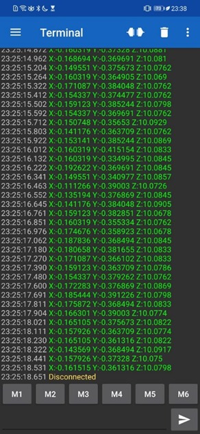
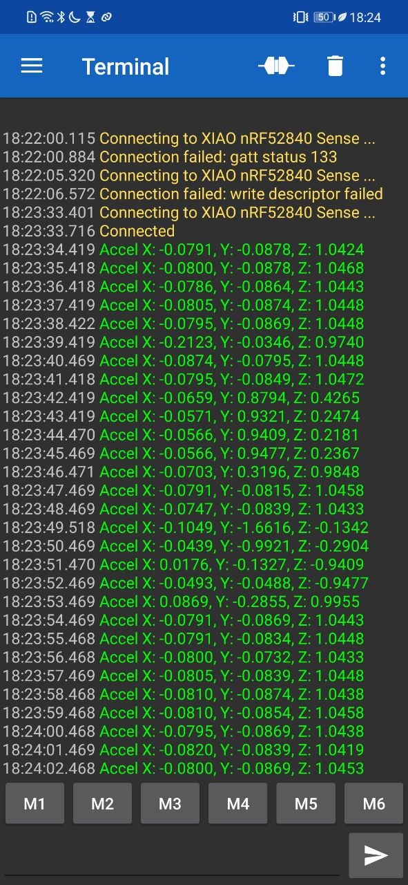
I used an Android phone to connect it to the board via Bluetooth, I downloaded the "Serial Bluetooth Termial" app to open a terminal and see the data:
ARDUINO IDE
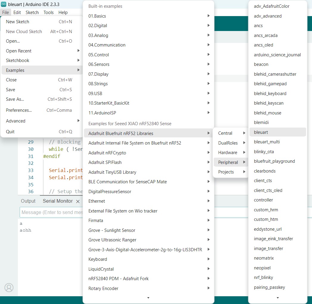
The second way I tried is by using Arduino IDE. The Seed Studio site explains how to download the right libraries. The zip file also contains several application examples.
After downloading the libraries, I opened the Arduino IDE and opened the following example code, this code connects to a phone to send and recieve data.
		#include   // Include the Bluefruit library for BLE functionality
		#include   // Include the LittleFS library for file system access
		#include   // Include the internal file system library

		// BLE Services
		BLEDfu  bledfu;  // OTA DFU (Device Firmware Update) service for firmware updates over BLE
		BLEDis  bledis;  // Device Information Service (provides device info like manufacturer, model, etc.)
		BLEUart bleuart; // UART over BLE service for serial communication via Bluetooth
		BLEBas  blebas;  // Battery Service for monitoring the battery level

		void setup()
		{
			// Start the serial communication at 115200 baud rate
			Serial.begin(115200);

			// If debugging is enabled, wait for the serial connection to be established
			#if CFG_DEBUG
			// Blocking wait for connection when debug mode is enabled via IDE
			while ( !Serial ) yield();
			#endif

			// Print information about the setup
			Serial.println("Bluefruit52 BLEUART Example");
			Serial.println("---------------------------\n");

			// Setup the BLE LED to be enabled on CONNECT
			// Note: This is actually the default behavior, but provided here in case you want to control it manually via PIN 19
			Bluefruit.autoConnLed(true);

			// Configure the peripheral connection with maximum bandwidth
			// More SRAM required by SoftDevice, but it allows faster data transfer
			// Note: All config***() functions must be called before Bluefruit.begin()
			Bluefruit.configPrphBandwidth(BANDWIDTH_MAX);

			// Initialize the Bluefruit module
			Bluefruit.begin();

			// Set the transmission power to 4 (range in dBm)
			Bluefruit.setTxPower(4);    // Check bluefruit.h for supported values

			// Set connection and disconnection callbacks
			Bluefruit.Periph.setConnectCallback(connect_callback);
			Bluefruit.Periph.setDisconnectCallback(disconnect_callback);

			// If OTA DFU service is present, it should be initialized first
			bledfu.begin();

			// Configure and start the Device Information Service with manufacturer and model information
			bledis.setManufacturer("Adafruit Industries");
			bledis.setModel("Bluefruit Feather52");
			bledis.begin();

			// Configure and start the BLE UART service for Bluetooth serial communication
			bleuart.begin();

			// Start the Battery Service with an initial value of 100 (full battery)
			blebas.begin();
			blebas.write(100);

			// Set up and start advertising the device
			startAdv();

			// Print instructions for connecting to the device using the Adafruit Bluefruit LE app
			Serial.println("Please use Adafruit's Bluefruit LE app to connect in UART mode");
			Serial.println("Once connected, enter character(s) that you wish to send");
		}

		void startAdv(void)
		{
			// Start setting up the advertising packet for BLE
			// Add the flags for BLE to advertise in "General Discovery Mode"
			Bluefruit.Advertising.addFlags(BLE_GAP_ADV_FLAGS_LE_ONLY_GENERAL_DISC_MODE);

			// Add the transmission power to the advertisement
			Bluefruit.Advertising.addTxPower();

			// Include the BLE UART 128-bit UUID in the advertising packet for identification
			Bluefruit.Advertising.addService(bleuart);

			// Configure the scan response to include the device name, since it's not included in the advertising packet
			Bluefruit.ScanResponse.addName();

			/* Start Advertising
			* - Enable auto advertising if disconnected
			* - Interval: Fast mode = 20 ms, Slow mode = 152.5 ms
			* - Timeout for fast mode is 30 seconds
			* - Start(timeout) with timeout = 0 will advertise forever (until connected)
			*/
			Bluefruit.Advertising.restartOnDisconnect(true);  // Restart advertising if disconnected
			Bluefruit.Advertising.setInterval(160, 320);      // Advertising interval in units of 0.625 ms
			Bluefruit.Advertising.setFastTimeout(30);         // Number of seconds in fast advertising mode
			Bluefruit.Advertising.start(0);                   // Start advertising indefinitely (until connected)
		}

		void loop()
		{
			// Forward data from HW Serial to BLEUART
			// This part sends data from the hardware serial interface to the BLE UART service
			while (Serial.available())
			{
			delay(2);  // Small delay to wait for enough input, as we have a limited transmission buffer
			uint8_t buf[64];  // Create a buffer to hold incoming data
			int count = Serial.readBytes(buf, sizeof(buf));  // Read bytes from Serial
			bleuart.write(buf, count);  // Write the received data to BLE UART
			}

			// Forward data from BLEUART to HW Serial
			// This part sends data from the BLE UART service to the hardware serial interface
			while (bleuart.available())
			{
			uint8_t ch = (uint8_t)bleuart.read();  // Read a byte from BLE UART
			Serial.write(ch);  // Write the byte to the serial output
			}
		}

		// Callback invoked when a central device connects
		void connect_callback(uint16_t conn_handle)
		{
			delay(500);  // Small delay before continuing

			// Get the reference to the current connection
			BLEConnection* connection = Bluefruit.Connection(conn_handle);

			char central_name[32] = { 0 };  // Array to hold the name of the connected central device
			connection->getPeerName(central_name, sizeof(central_name));  // Retrieve the name of the connected device

			// Print the name of the connected central device
			Serial.print("Connected to ");
			Serial.println(central_name);
		}

		/**
			* Callback invoked when a connection is dropped (disconnected)
			* @param conn_handle Connection handle where this event happens
			* @param reason The reason for disconnection, specified by a BLE_HCI_STATUS_CODE (found in ble_hci.h)
			*/
		void disconnect_callback(uint16_t conn_handle, uint8_t reason)
		{
			(void) conn_handle;  // Ignore the connection handle
			(void) reason;  // Ignore the reason code for disconnection

			// Print a message when disconnected
			Serial.println();
			Serial.print("Disconnected, reason = 0x"); Serial.println(reason, HEX);
		}
I have never programmed this board using Arduino IDE so I also researched how to read the data from the accelerometer, I found a section called “The 6-Axis IMU Usage on Seeed Studio XIAO nRF52840 Sense” which explains how to view the data on the serial monitor.
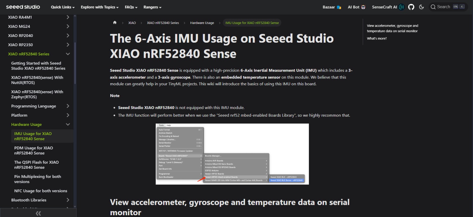
The following example shows on the serial monitor the data from the built-in sensors.
	#include "LSM6DS3.h"  // Include the LSM6DS3 sensor library (for accelerometer, gyroscope, and thermometer)
	#include "Wire.h"      // Include the Wire library for I2C communication

	// Create an instance of the LSM6DS3 class for I2C communication
	// The device address 0x6A is used for communication over I2C
	LSM6DS3 myIMU(I2C_MODE, 0x6A);    // I2C device address 0x6A

	void setup() {
		// Initialize serial communication at 9600 baud rate
		Serial.begin(9600);

		// Wait until the Serial connection is established (useful for some boards like Leonardo)
		while (!Serial);

		// Call the .begin() method to initialize the IMU (accelerometer, gyroscope, and thermometer)
		if (myIMU.begin() != 0) {
		// If the IMU initialization fails, print an error message
		Serial.println("Device error");
		} else {
		// If the IMU is successfully initialized, print a success message
		Serial.println("Device OK!");
		}
	}

	void loop() {
		// Read and display accelerometer values
		Serial.print("\nAccelerometer:\n");
		Serial.print(" X1 = ");
		// Read the accelerometer X-axis value (in g) and print it with 4 decimal places
		Serial.println(myIMU.readFloatAccelX(), 4);

		Serial.print(" Y1 = ");
		// Read the accelerometer Y-axis value (in g) and print it with 4 decimal places
		Serial.println(myIMU.readFloatAccelY(), 4);

		Serial.print(" Z1 = ");
		// Read the accelerometer Z-axis value (in g) and print it with 4 decimal places
		Serial.println(myIMU.readFloatAccelZ(), 4);

		// Read and display gyroscope values
		Serial.print("\nGyroscope:\n");
		Serial.print(" X1 = ");
		// Read the gyroscope X-axis value (in degrees per second) and print it with 4 decimal places
		Serial.println(myIMU.readFloatGyroX(), 4);

		Serial.print(" Y1 = ");
		// Read the gyroscope Y-axis value (in degrees per second) and print it with 4 decimal places
		Serial.println(myIMU.readFloatGyroY(), 4);

		Serial.print(" Z1 = ");
		// Read the gyroscope Z-axis value (in degrees per second) and print it with 4 decimal places
		Serial.println(myIMU.readFloatGyroZ(), 4);

		// Read and display temperature values
		Serial.print("\nThermometer:\n");
		Serial.print(" Degrees C1 = ");
		// Read the temperature in Celsius and print it with 4 decimal places
		Serial.println(myIMU.readTempC(), 4);

		Serial.print(" Degrees F1 = ");
		// Read the temperature in Fahrenheit and print it with 4 decimal places
		Serial.println(myIMU.readTempF(), 4);

		// Wait for 1 second before reading the sensor data again
		delay(1000);
	}
I used the two examples to build the following code:
	#include bluefruit.h             // Include the Bluefruit library for Bluetooth LE communication
	#include Adafruit_LittleFS.h     // Include the Adafruit LittleFS library for file system support
	#include InternalFileSystem.h    // Include the internal file system for storage (if needed)
	#include "LSM6DS3.h"               // Include the LSM6DS3 library for sensor communication (accelerometer, gyroscope, thermometer)
	#include "Wire.h"                  // Include the Wire library for I2C communication

	// BLE Service Setup
	BLEDfu bledfu;  // OTA DFU (Device Firmware Update) service
	BLEDis bledis;  // Device Information Service (advertises device information)
	BLEUart bleuart; // UART over BLE (used for sending data over Bluetooth)
	BLEBas blebas;  // Battery Service (used for battery level information)

	// Create an instance of the LSM6DS3 IMU (accelerometer, gyroscope, thermometer)
	LSM6DS3 myIMU(I2C_MODE, 0x6A);    // I2C device address 0x6A for communication

	void setup() {
		// Initialize serial communication at 115200 baud rate
		Serial.begin(115200);

		// Debugging setup: Ensure Serial monitor is available
		#if CFG_DEBUG
		// Wait until the Serial connection is established (useful for some boards like Leonardo)
		while (!Serial) yield();
		#endif

		// Initialize the IMU sensor (LSM6DS3)
		if (myIMU.begin() != 0) {
		// If IMU initialization fails, print error message
		Serial.println("Device error");
		} else {
		// If IMU is initialized successfully, print success message
		Serial.println("Device OK!");
		}

		// Setup the BLE LED to be enabled when the device connects
		Bluefruit.autoConnLed(true);

		// Configure the peripheral connection with maximum bandwidth
		Bluefruit.configPrphBandwidth(BANDWIDTH_MAX);

		// Initialize Bluefruit and configure BLE settings
		Bluefruit.begin();
		Bluefruit.setTxPower(4);    // Set transmission power (adjust according to your needs)
		Bluefruit.Periph.setConnectCallback(connect_callback);   // Set the callback for when a central device connects
		Bluefruit.Periph.setDisconnectCallback(disconnect_callback);  // Set the callback for when a central device disconnects

		// Initialize OTA DFU service if available
		bledfu.begin();

		// Set up and start the Device Information Service
		bledis.setManufacturer("Adafruit Industries");
		bledis.setModel("Bluefruit Feather52");
		bledis.begin();

		// Set up and start the BLE UART service for communication over BLE
		bleuart.begin();

		// Start the Battery Service and set battery level to 100%
		blebas.begin();
		blebas.write(100);

		// Start BLE advertising (advertise this device to others)
		startAdv();
	}

	void startAdv(void) {
		// Add flags to the advertising packet
		Bluefruit.Advertising.addFlags(BLE_GAP_ADV_FLAGS_LE_ONLY_GENERAL_DISC_MODE);
		Bluefruit.Advertising.addTxPower();  // Add transmission power level to the packet

		// Add the BLE UART service UUID (used for UART communication over BLE)
		Bluefruit.Advertising.addService(bleuart);

		// Add a secondary scan response packet (optional)
		// This is used to send additional data such as the device name
		Bluefruit.ScanResponse.addName();

		// Start advertising with the following settings:
		// - Enable auto advertising if disconnected
		// - Set advertising interval (fast mode = 20 ms, slow mode = 152.5 ms)
		// - Timeout for fast mode is 30 seconds
		Bluefruit.Advertising.restartOnDisconnect(true);
		Bluefruit.Advertising.setInterval(160, 320);  // Set the advertising interval (in units of 0.625 ms)
		Bluefruit.Advertising.setFastTimeout(30);     // Timeout for fast advertising mode (30 seconds)
		Bluefruit.Advertising.start(0);               // Start advertising indefinitely until connected
	}

	void loop() {
		// Read accelerometer data (X, Y, Z axes)
		float accelX = myIMU.readFloatAccelX();
		float accelY = myIMU.readFloatAccelY();
		float accelZ = myIMU.readFloatAccelZ();

		// Format the accelerometer data into a string
		String accelData = "Accel X: " + String(accelX, 4) + ", Y: " + String(accelY, 4) + ", Z: " + String(accelZ, 4);

		// Send the accelerometer data over BLE if connected
		if (Bluefruit.connected()) {
		bleuart.println(accelData);  // Send the data over the UART service (BLE)
		}

		// Also print the accelerometer data to the Serial Monitor
		Serial.println(accelData);

		// Delay for a second before taking the next reading
		delay(1000);
	}

	// Callback invoked when a central device connects to this peripheral
	void connect_callback(uint16_t conn_handle) {
		delay(500);  // Small delay before continuing after connection
		// Get the reference to the current connection
		BLEConnection* connection = Bluefruit.Connection(conn_handle);

		// Get and print the name of the central device
		char central_name[32] = { 0 };
		connection->getPeerName(central_name, sizeof(central_name));

		// Print connection message to the Serial Monitor
		Serial.print("Connected to ");
		Serial.println(central_name);
	}

	/**
		* Callback invoked when a connection is dropped (disconnected)
		* @param conn_handle The connection handle of the connection that was dropped
		* @param reason The reason for the disconnection (in BLE_HCI_STATUS_CODE)
		*/
	void disconnect_callback(uint16_t conn_handle, uint8_t reason) {
		(void) conn_handle;  // Ignore the connection handle as it's not needed here
		(void) reason;       // Ignore the reason for disconnection as it's not needed here

		// Print disconnection message to the Serial Monitor
		Serial.println();
		Serial.print("Disconnected, reason = 0x");
		Serial.println(reason, HEX);  // Print the disconnection reason in hexadecimal format
	}
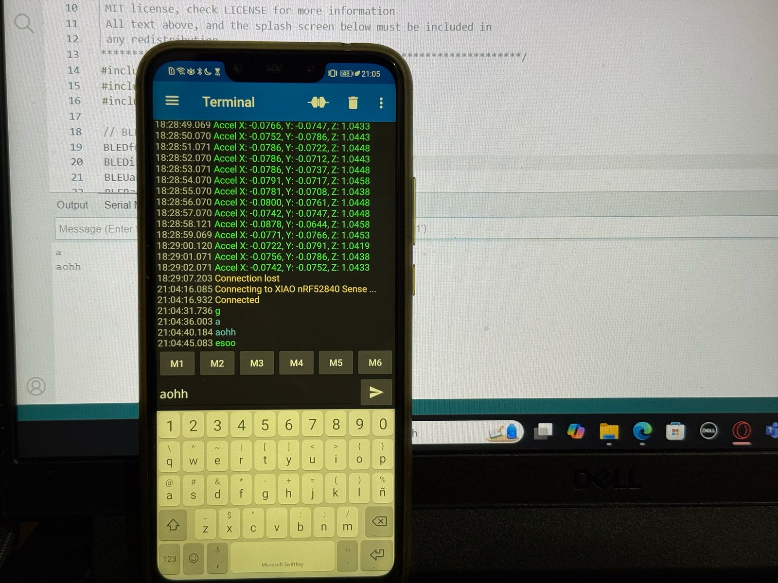
I connected the board to my phone using the same app:
Summary
I found that these two options are useful for programming the board but the Arduino IDE used more complex programming configurations that can be useful depending on the use case. I will come down to personal preference on which option you choose. I think I’ll be using CircuitPython to program this XIAO since it’s easier to use and I have used Arduino IDE to program other boards and I want to get used to Python.