2. Computer-aided design
Computer-aided design (CAD) is the use of computer-based software to aid in design processes of simulating real-world objects. CAD software is frequently used, to create two-dimensional drawings or 3D models. This week I compared two 2D and 3D CAD programs .
2D Design
The 2D softwares I´ll compare are Procreate and Inkscape. During high school I learned how to use CorelDraw, so Inkscape will be pretty familiar.
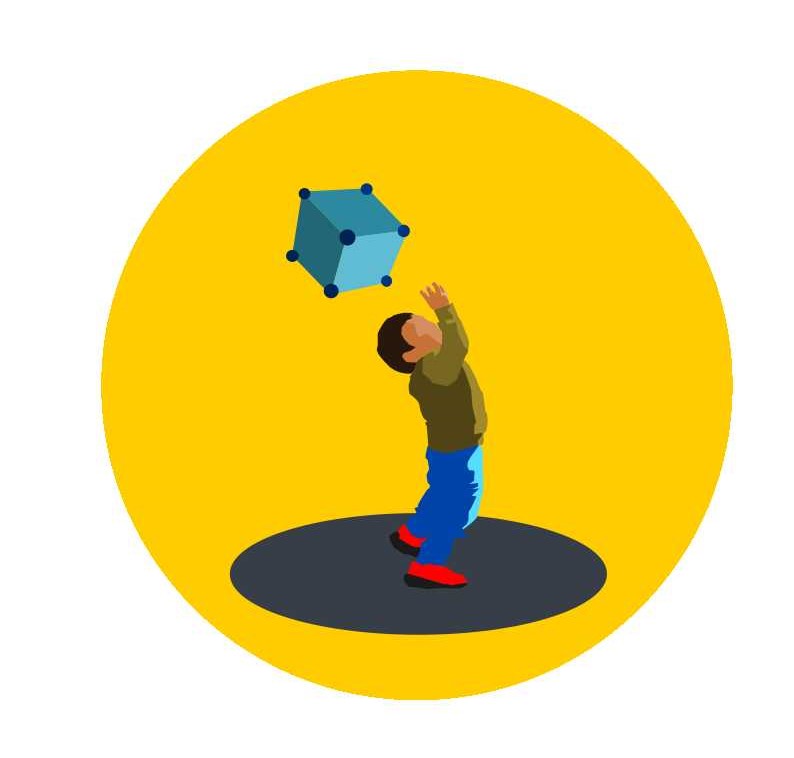
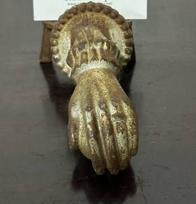
I´ll be making my final project logo in both softwares using this photo as a reference:

I´ll add the reference image in the bottom layer and then in a different layer(s) I will use a brush to mark the drawing´s outline and fill the shapes with the selected colors.
Procreate is a drawing app for iPad, it has a lot of features to make illustrations, animations, and designs.
When you open the app a menu will appear, to create a new project select "new canvas".
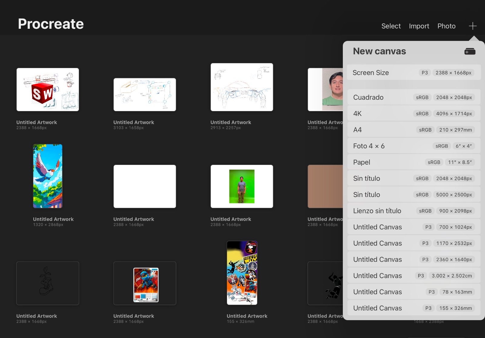
On the right side brushes, colors, and layers will appear. On the top bar the "Actions" are the first tools that shows up. These will create a new project, save, or export the project. On the right side you can modify the brush size and opacity.
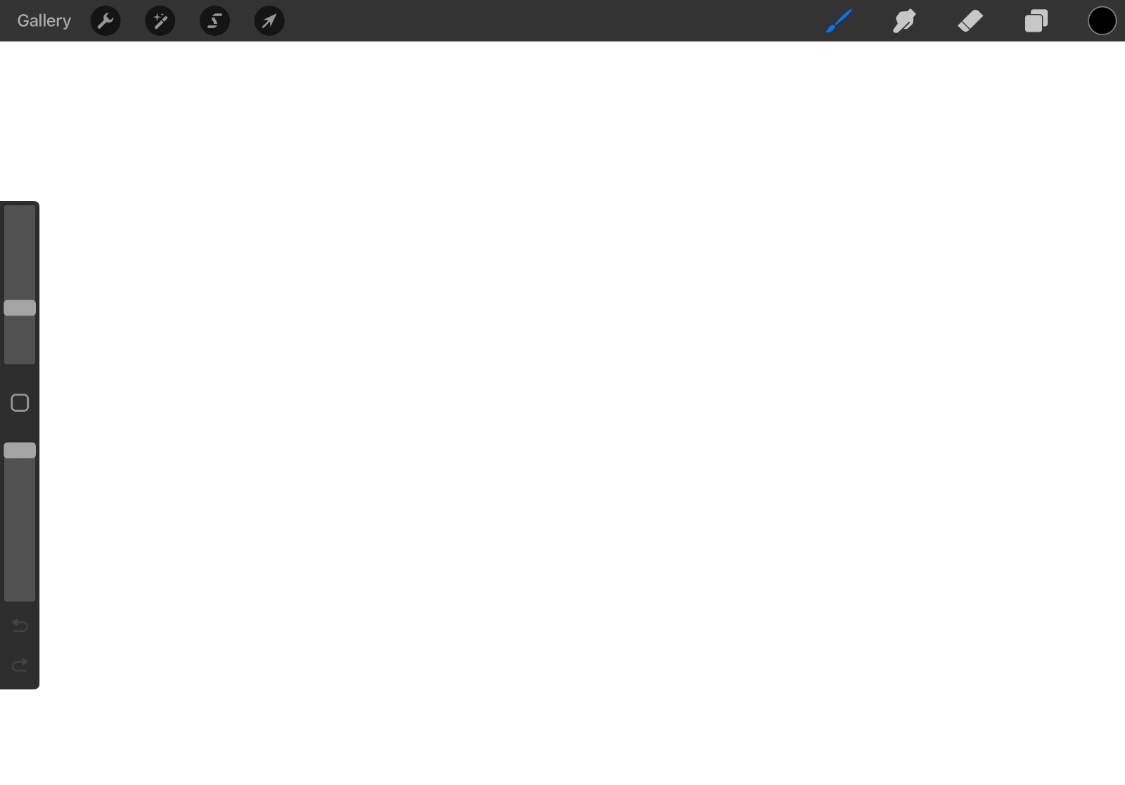
Procreate Interface
The second tools menu is called "Brushes" and here is where all the tools to draw are located.
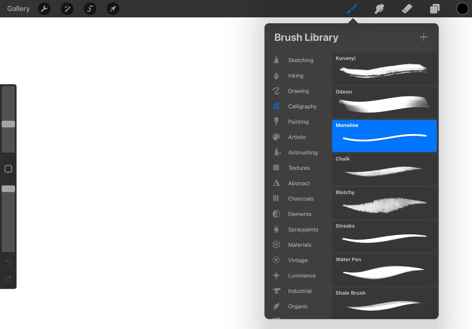
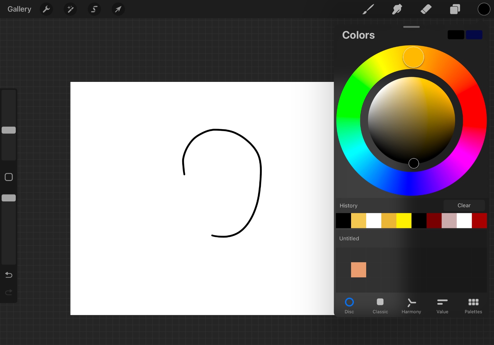
For the drawing we´ll be creating first, select the brush tool and start drawing.
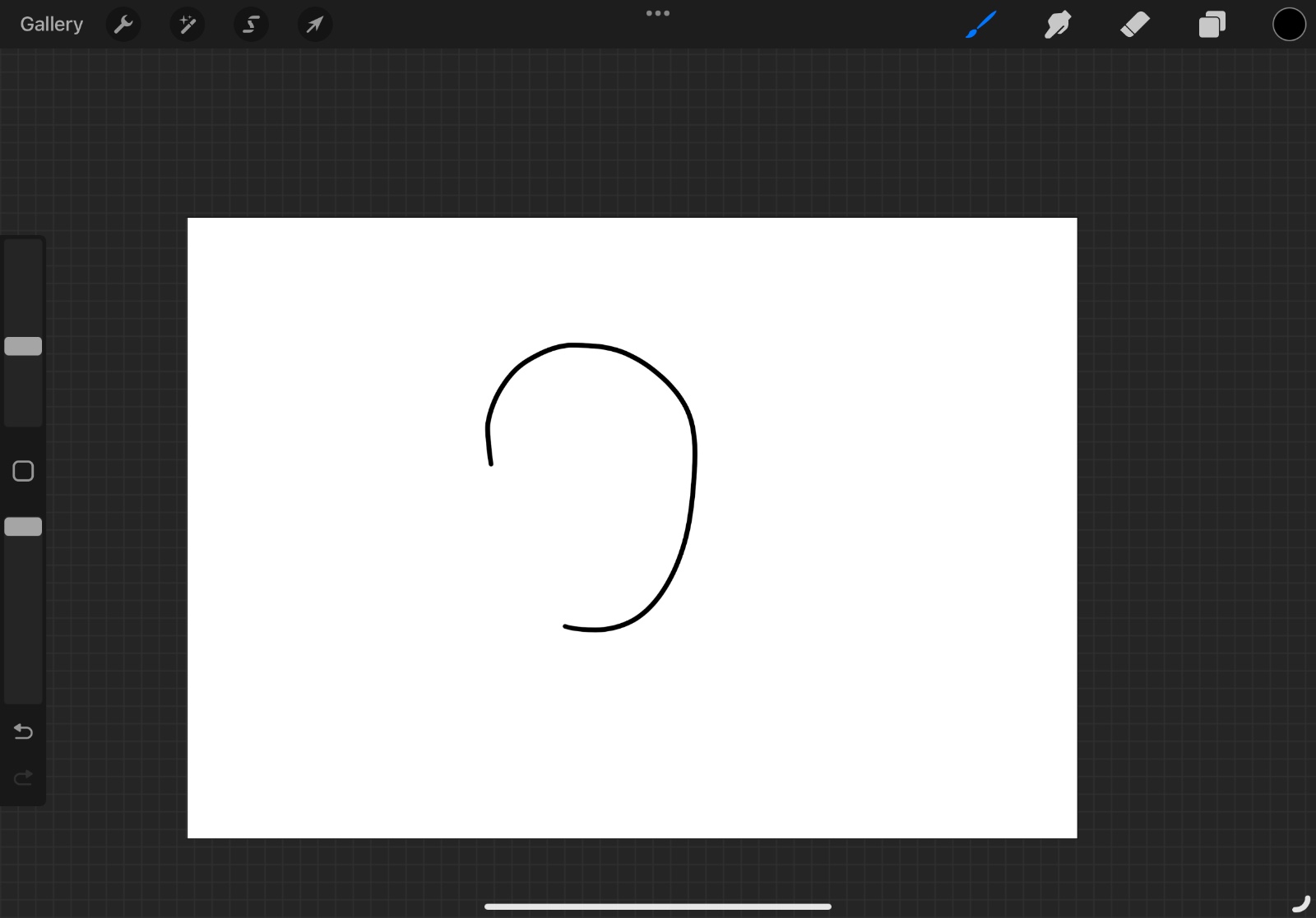
To change color you can use the color disc, classic, harmony or value windows. The current color will appear on the top right corner of the screen inside of a circle.
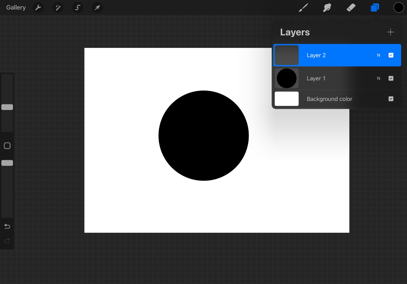
After making a drawing, you can select the "Layers" tool to add a new layer (top right corner). This is useful to make changes without affecting the original drawing.
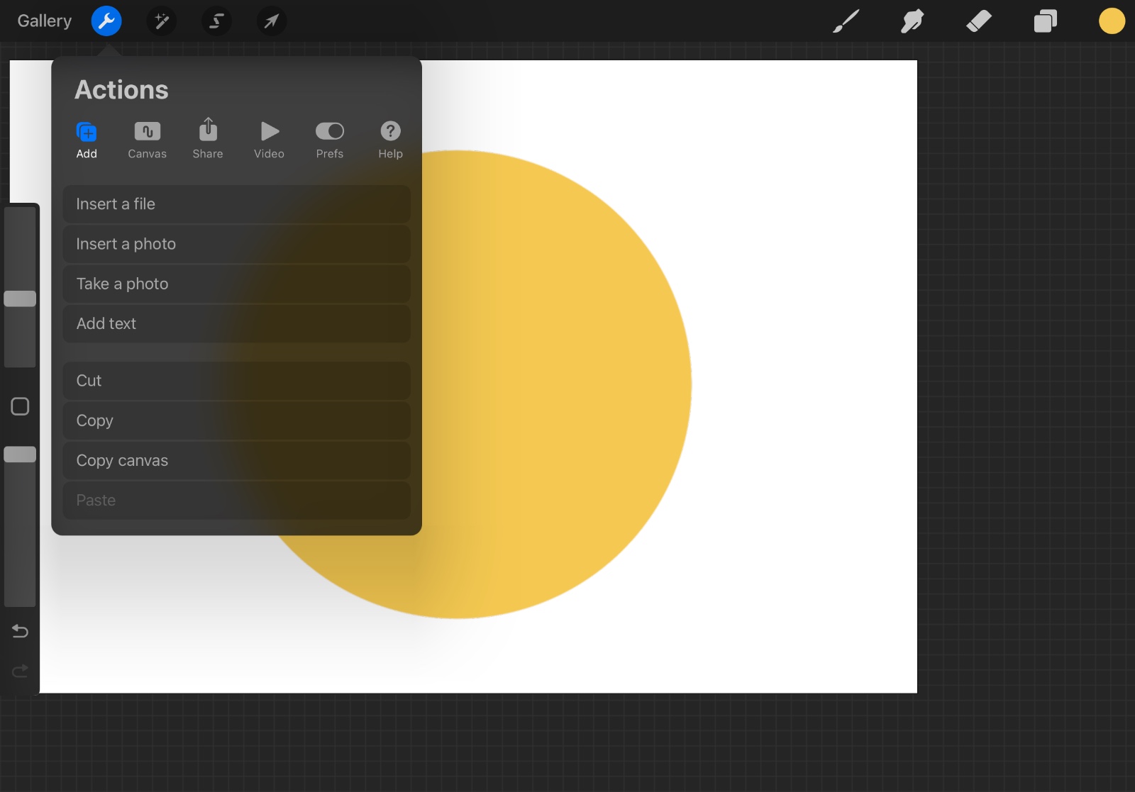
You can import an image to use it as a reference by clicking on the wrench icon and then select "Add" and "Insert a photo".
After finishing the drawing, you can select the "Actions" tool and select "Share" to export the drawing.
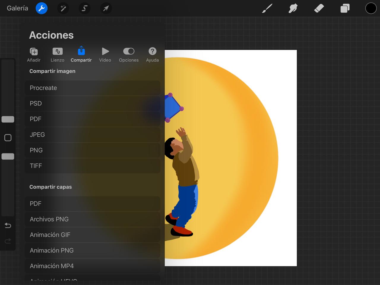
Here´s the final result:

Inkscape is a free software for making vector graphics. It has a lot of tools to make precise shapes and drawings.
When you open the program a menu will appear, to create a new project select "New document".
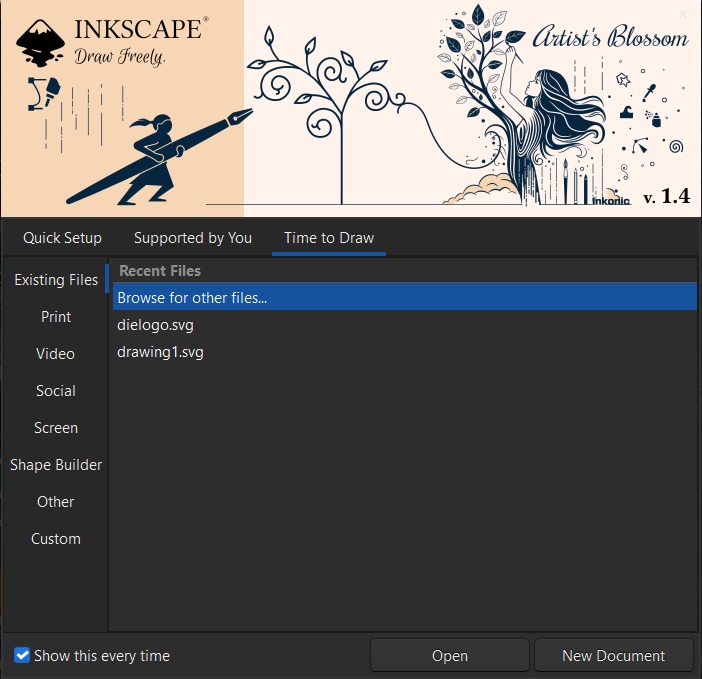
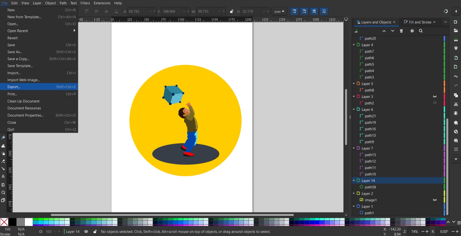
On the left side you will find tools to draw, colors will appear on the bottom. On the top bar the other tools will be located.
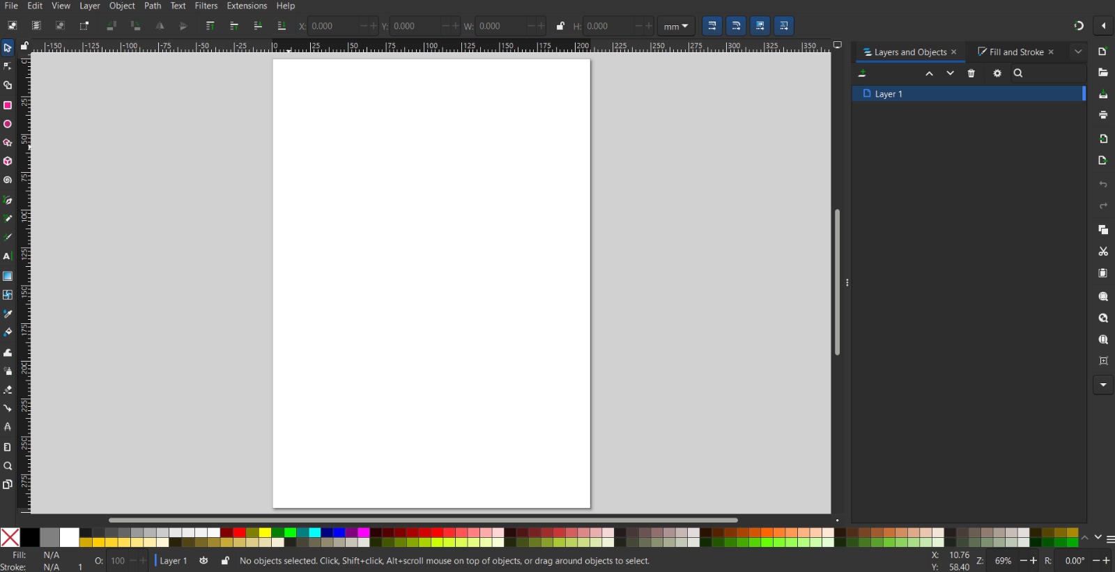
For the drawing we´ll be creating first, select the pencil tool and a color to start drawing.
After making a drawing, you can select the "Layers" tool to add a new layer. This is useful to make changes to different parts of the drawing without changing everything.
You can import an image to use it as a reference by clicking on File > Export. You can add the image to a different layer.
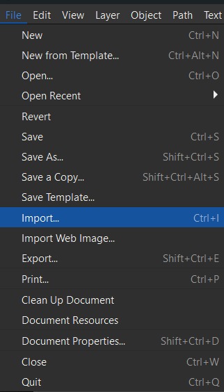
I used the Pen Tool to make the outlines and fill it automatically.
After finishing the drawing, you can select the "File" tool and select "Export" to save the drawing as an image.
Here´s the final result:
3D Design
For this comparison I´ll be using SOLIDWORKS and Fushion 360. SOLIDWORKS is a software used by engineers across multiple industries around the world. You can assembly parts, make animations, and simulate. Fusion 360 it´s a cloud-based 3D CAD so it is better for collaboration. Also used for products design and engineering.
Features
| Feature | Fusion 360 | SolidWorks |
|---|---|---|
| 3D Design & Modeling | Create 3D models of products | Create detailed 3D models of products, from simple parts to complex assemblies |
| Simulation | Run simulations to test designs | Analyze physical behavior with stress tests, fluid dynamics, and thermal analysis |
| Generative Design | Use generative design tools to create optimized designs | Not a core feature |
| Documentation | Create documentation for designs | Generate precise drawings and specifications for manufacturing |
| Collaboration | Cloud-based collaboration tools for teamwork | Not cloud-native; requires additional tools for collaboration |
| Manufacturing | Supports CNC machining and other manufacturing processes | Supports CNC machining, 3D printing, and manufacturing specifications |
| Rendering | Create photorealistic renderings of designs | Rendering tools available |
| Electrical Design | Not a core feature | Built-in tools for wiring and PCB layout |
| Sheet Metal & Weldments | Basic sheet metal tools | Specialized tools for sheet metal and welded structures |
| Primary Uses | Fusion 360 | SolidWorks |
| Industries | Industrial design, engineering, product design, prototyping | Engineering, design, architecture |
We are going to explore a feature to build a part on SOLIDWORKS, but first here´s a quick look of the main features to build a 3D model.
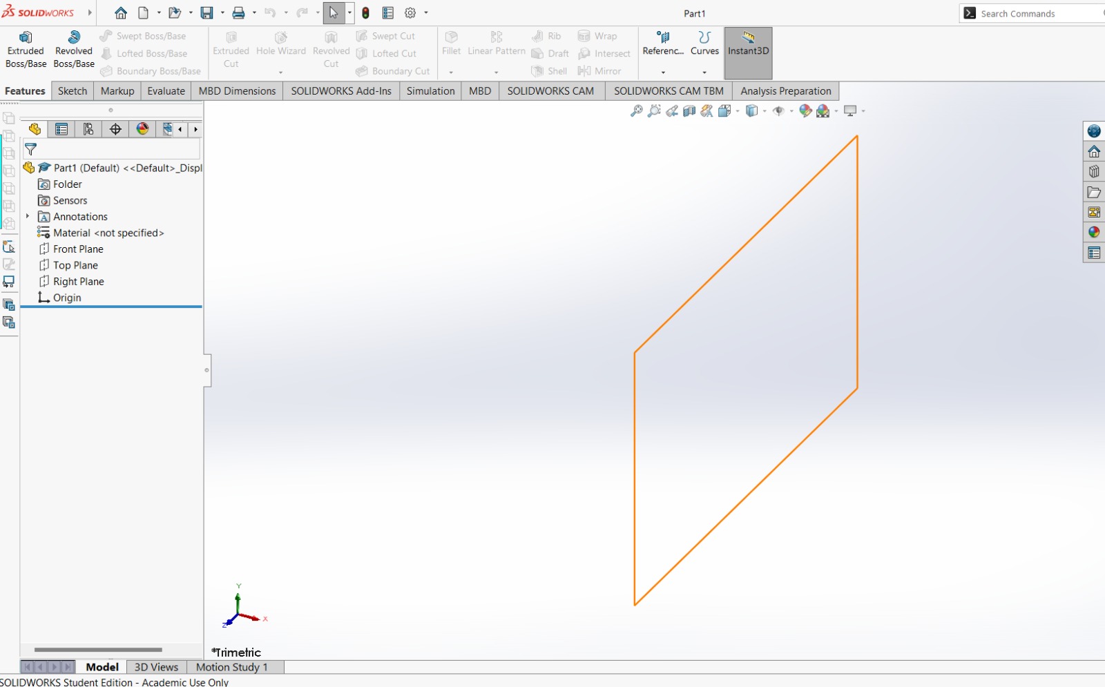
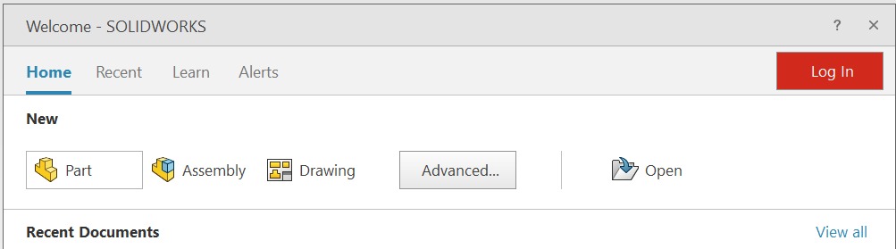
SolidWorks Interface
When you open the program a menu will appear, to create a new model select "part".
On the left side planes, sketches and operations will appear. On the top bar the "Features" are the first tools that shows up. These will create o delete parts of the 3D model.
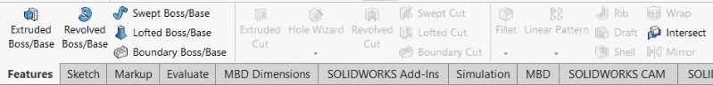
The second tools menu is called "Sketch" and here is where all the tools to draw are located.
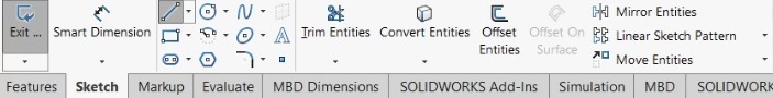
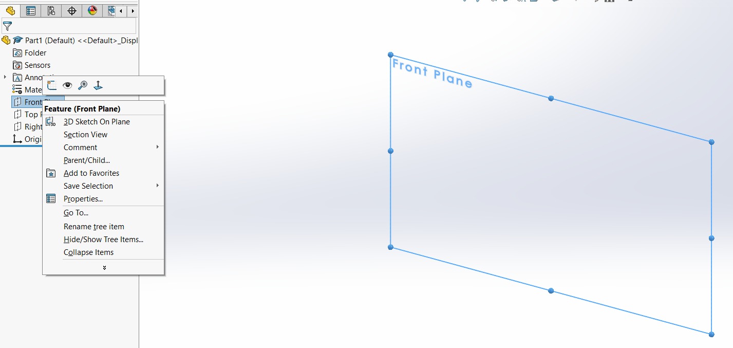
For the part we´ll be creating first, right click on one of the three planes available and select sketch.
Using the Circle tool from the Sketch menu we´ll create the first form.
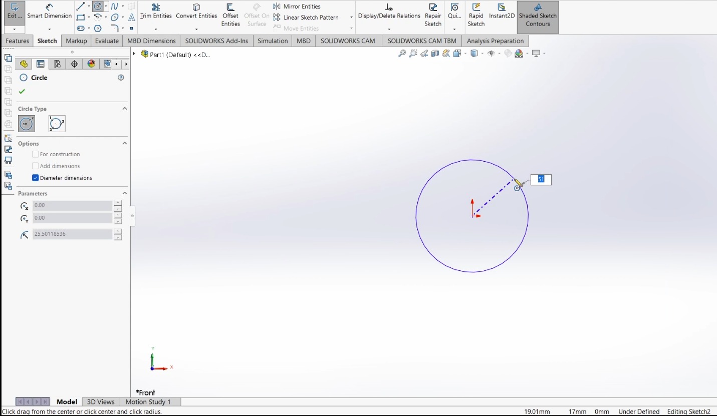
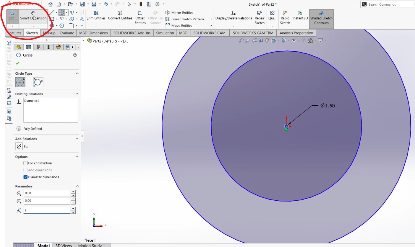
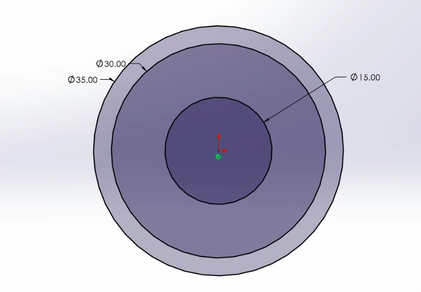
After making two more circles, you can select the Smart Dimension tool to give the circles the desired diameter
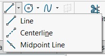
Then, select the Centerline tool to make two lines, these lines will be a guide to help you build certain geometries
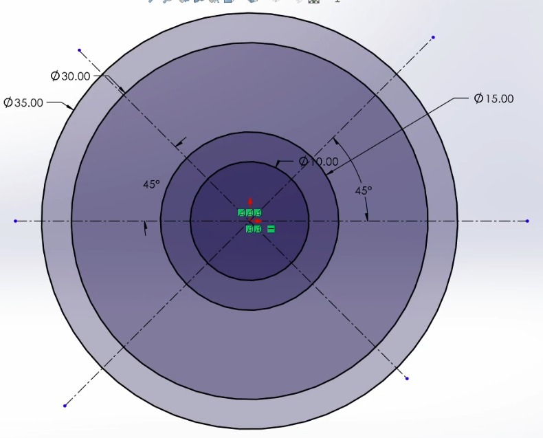
Create four lines coincident to the center lines that are at 45°, and only touching the two outer circles
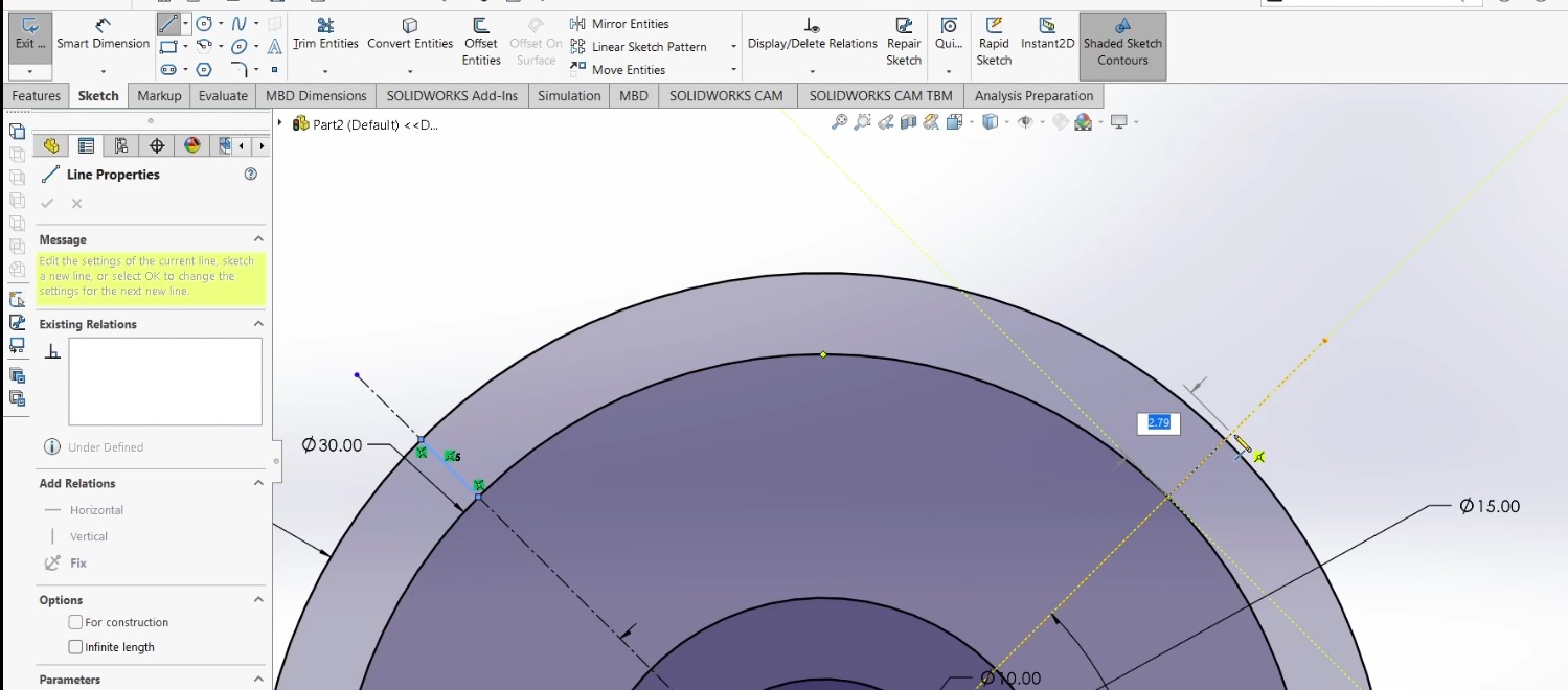
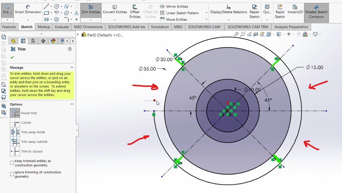
In the following image I marked with green the lines to create. Using the Trim Entities tool you can delete parts of lines and other entities that are not needed. The tool will only delete the part of line that doesn´t intersect with other line.
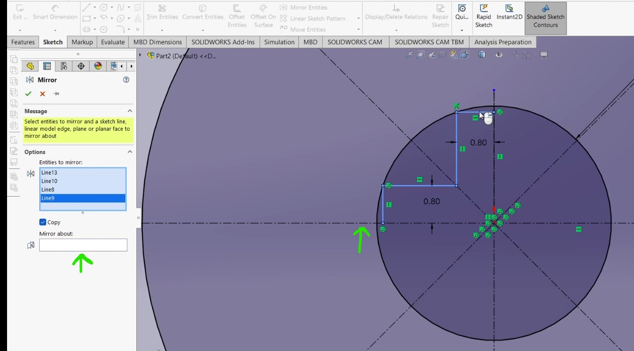
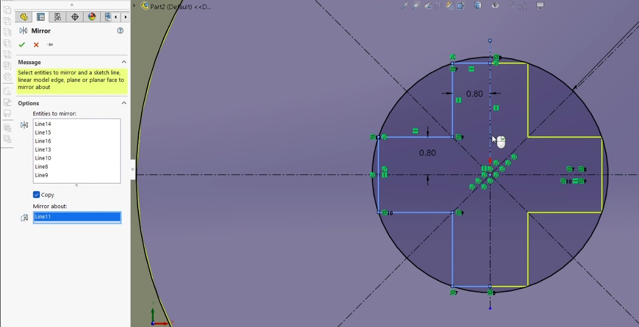
After deleting the unnecessary parts, I created a cross using the Mirror tool, first I created a quarter of the cross and added a vertical centerline.
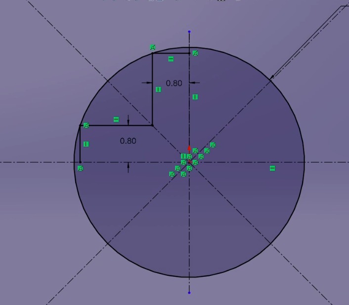
Select the tool and select the box below the text "entities to mirror" select the 4 lines, and in the box below "mirror about" select the horizontal centerline (in green). Click the checkmark and repeat the process selecting the vertical centerline.
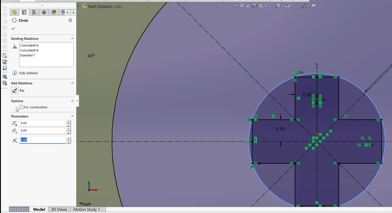
Double click on the smallest circle and on the left side select "for construction"
The following steps will show the feature I mentioned earlier:
On the right side click on "exit sketch"
Click on the "Features" menu and select "Extruded Boss/Base". In the following video you can see how I selected different parts of the sketch to give the model different thicknesses. This is really useful to make fast models, since you only use one sketch.
Playing with this program I discovered you can make very interesting shapes, so here´s a quick look:
When you open the program a menu will appear, to create a new model select "new design".
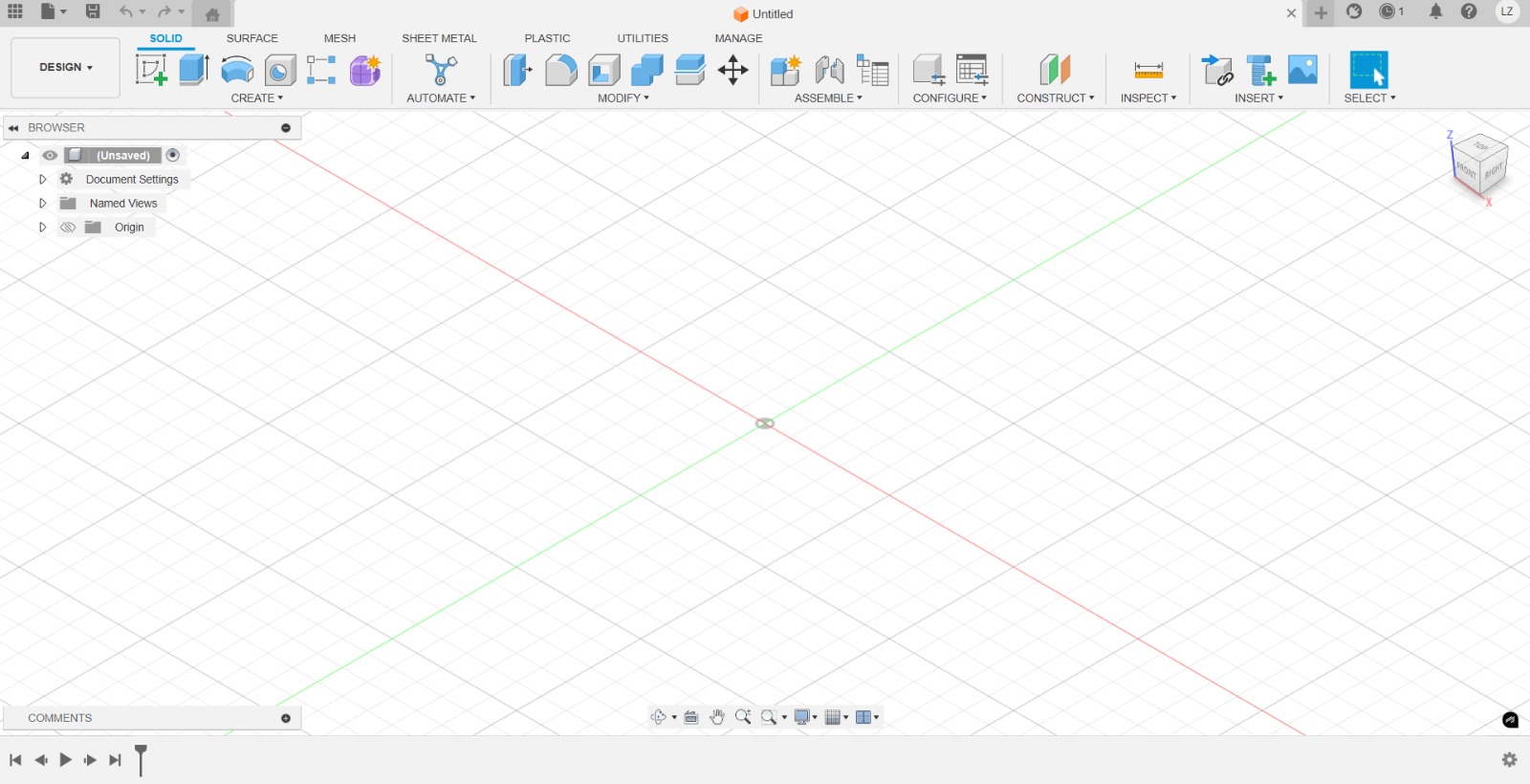
Fushion 360 interface.
You´ll find almost every feature from SOLIDWORKS, but probably with a different name. On the top part select Create Form.
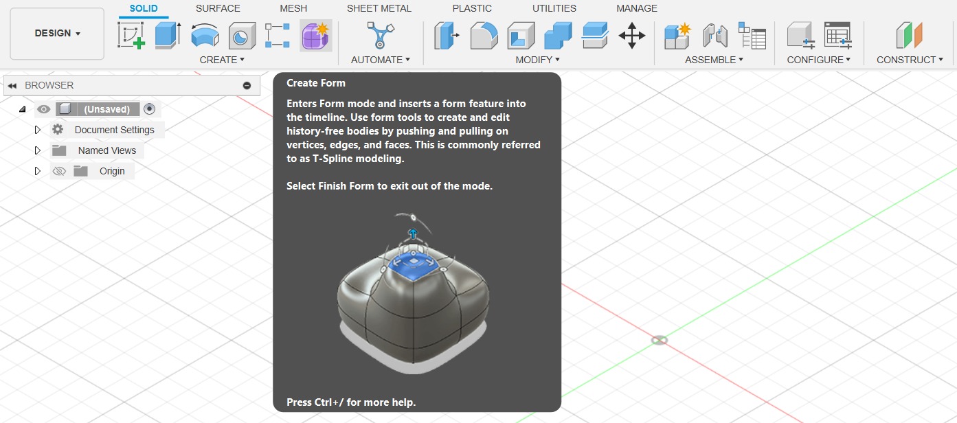
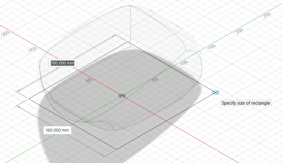
After selecting the Create Form tool, a new menu will appear. Select the "Box" tool and then select a plane to start building the part.
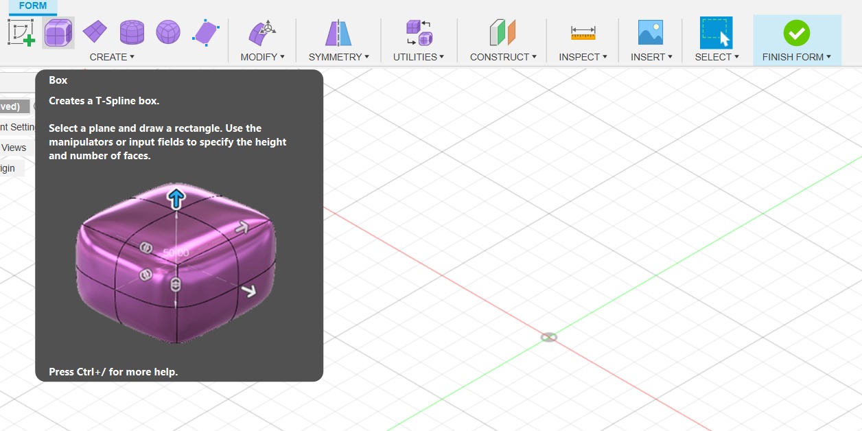
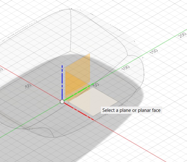
After selecting the plane, a box will appear. You can change the dimensions of the box by dragging the arrows.
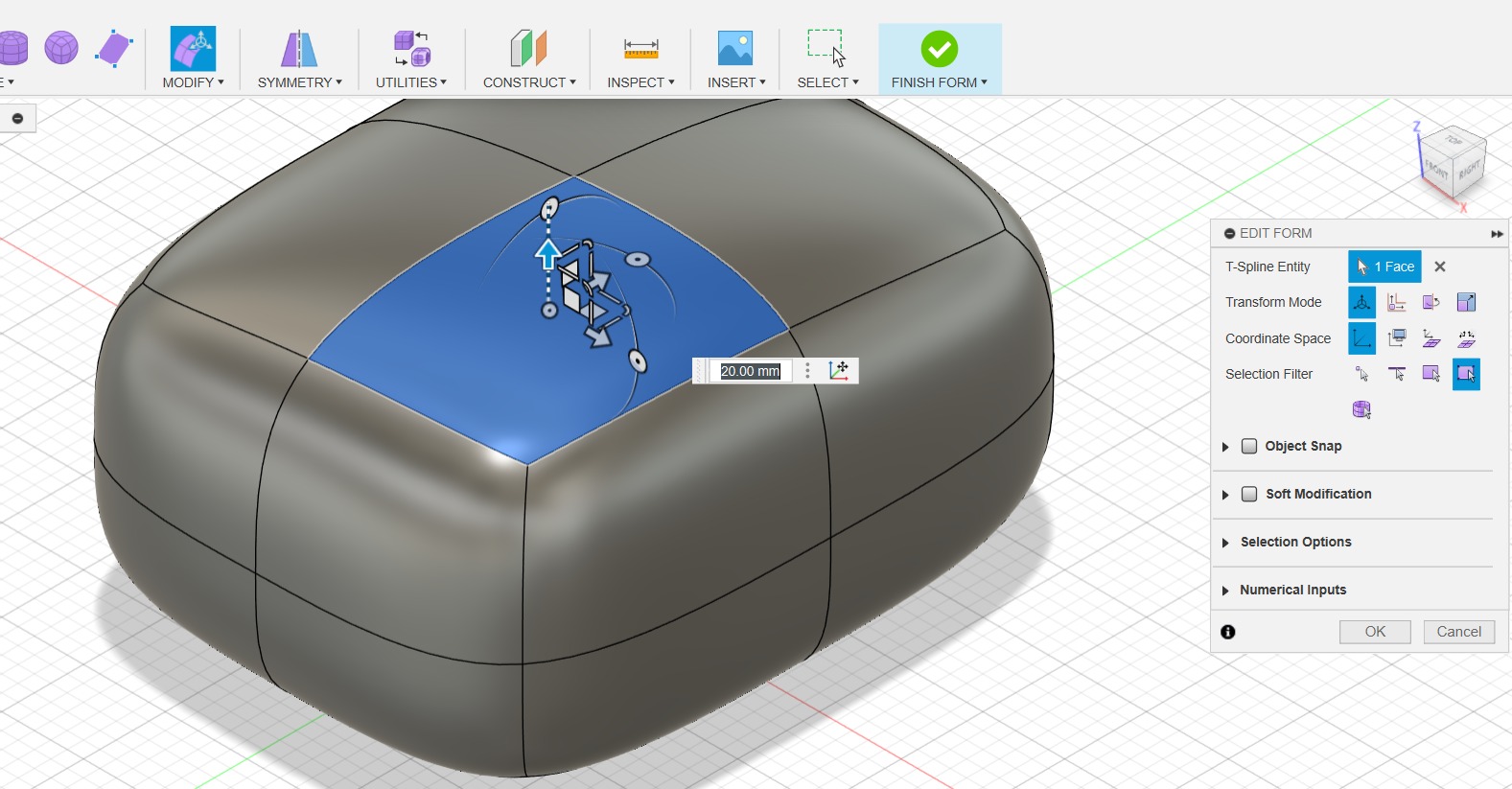
Select the Modify tool to edit a face, you will see that depending on the arrow you click on, the face will move around.
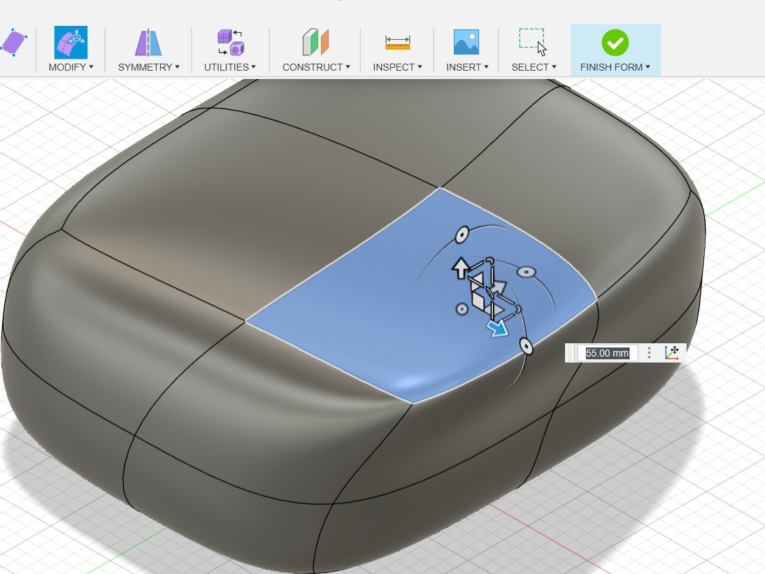
When you are done click on "Finish form" and you will see the end result.
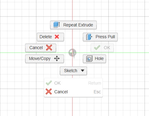
We are going to use the Extrude and Revolve tools to make a new form. First select a plane and right-click to reveal a menu and select sketch.
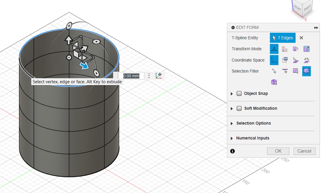
We are going to use the Cylinder tool from the "From" menu.
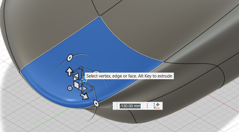
Select the following lines and select the "Edit form" tool to modify the shape.
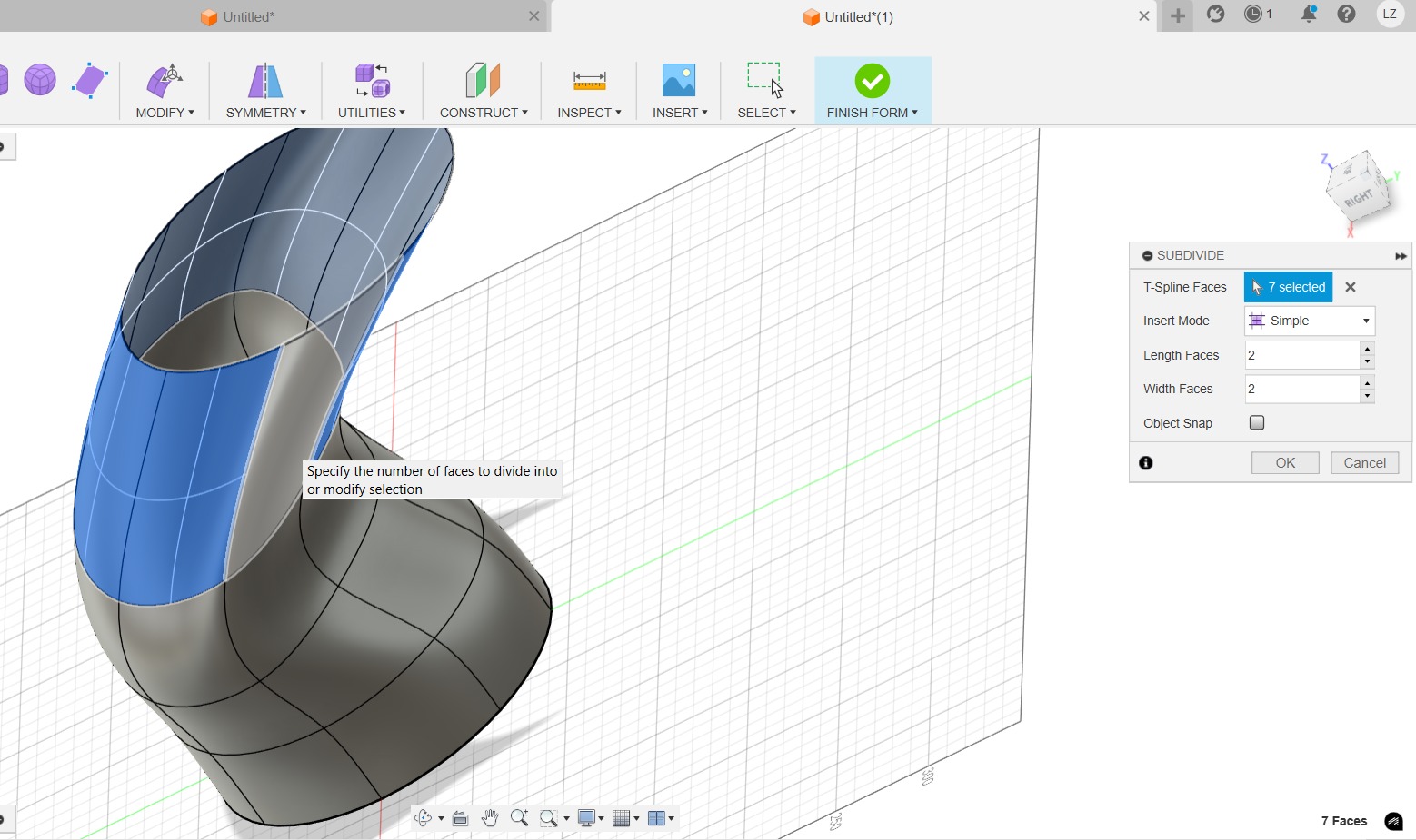
You can use the "Subdivide" tool to add extra faces
Move the faces to make a desired form and use "fill hole" to close the form.
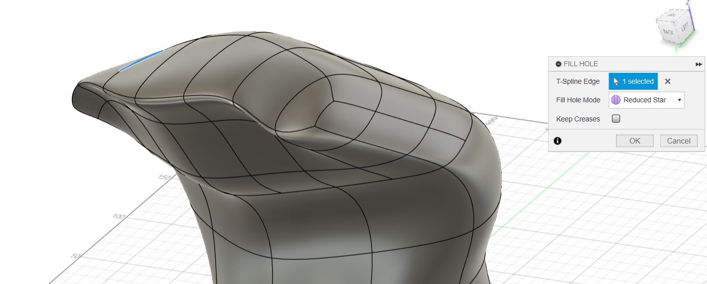
You can move faces, lines and points to change the model´s shape.
3D models
Here is the final model from SOLIDWORKS:
I made this part as an early idea for the box mechanism for my final project.
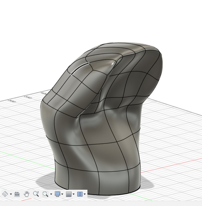
Here is the final model from Fushion 360:
I tried to design this piece to imitate a hand door knocker:
Animations and Rendering
I used SOLIDWORKS to animate a gear and a rack and I rendered the part that I built earlier.
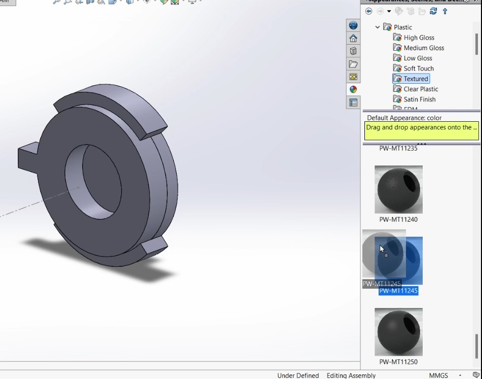
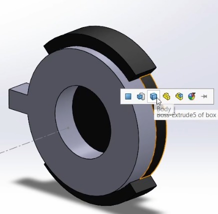
To render the part, select the material (in green) and drag it to the part. A small box will appear, select body and click the checkmark.
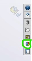
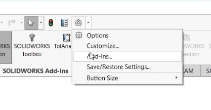
To open the tool click on the gear at the top part of the menu and select Add-ins
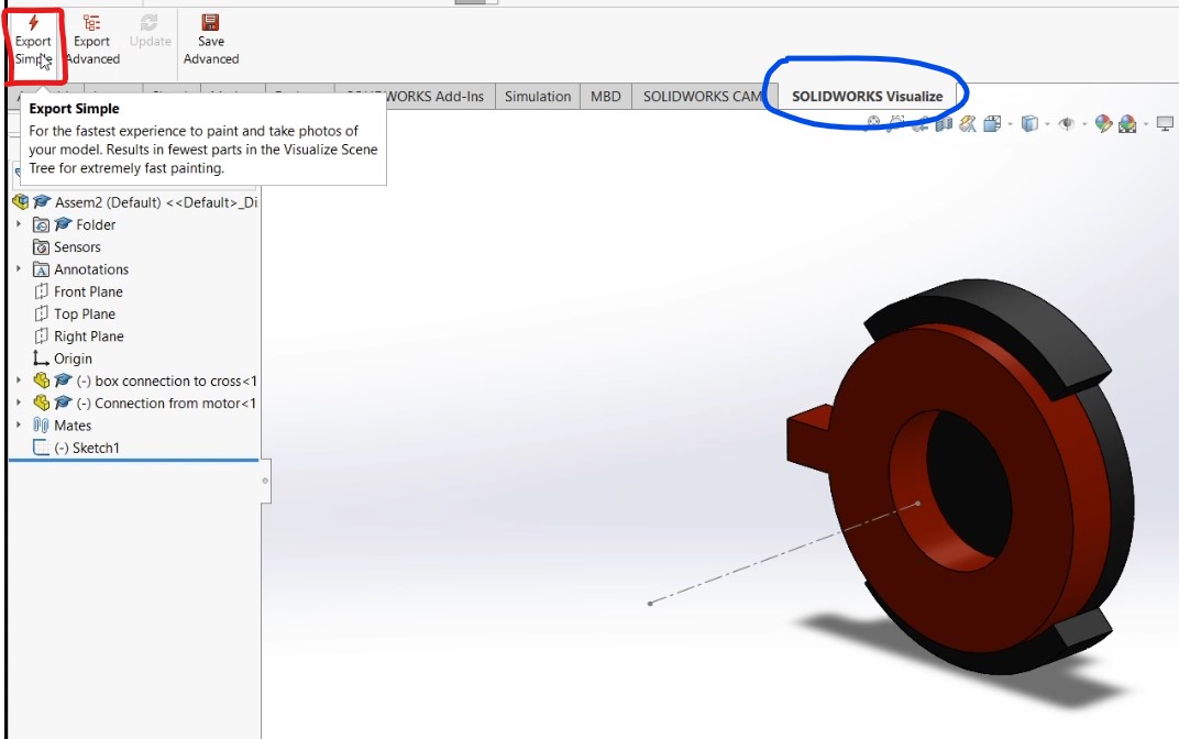
After selecting the Add-ins, a window will pop up, select SOLIDWORKS Visualize

After selecting Visualize it will appear on the bottom part of the toolbar (blue) click on it and then new tools will show up, select "Export Simple" (Red).
After selecting the export tool, a window will pop up.
Inside the program you will see the part in a "scenario" on the top-middle part you can add a turntable (green), and the object manipulating tool (blue).
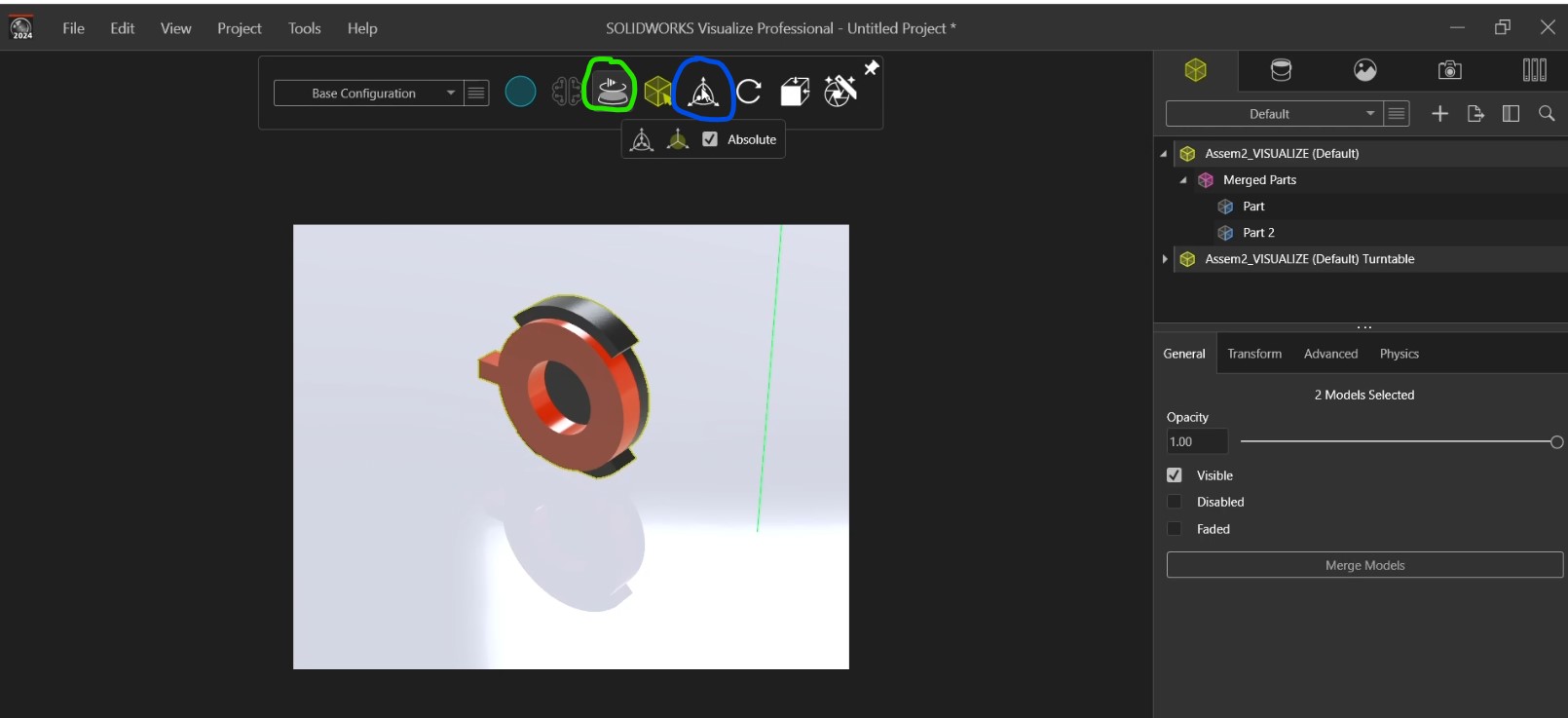
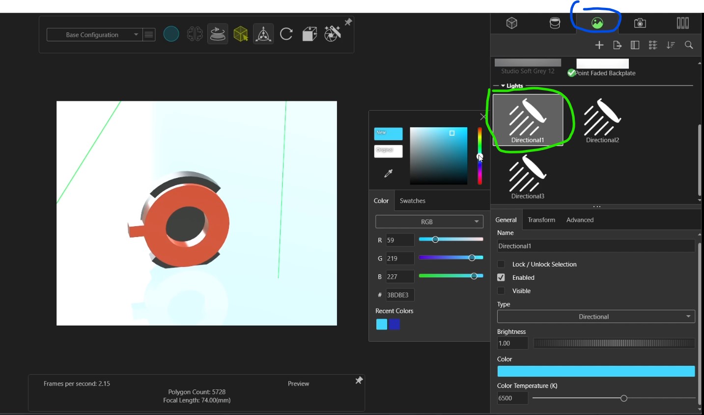
If you click on the image icon (blue) and then select a Directional light (green), you can change the scene illumination color.
After finishing the changes, click on the Render Wizard tool. After selecting the Render Wizard, a window will pop up.
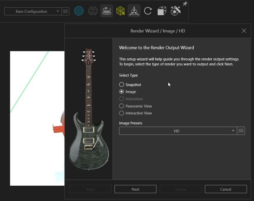
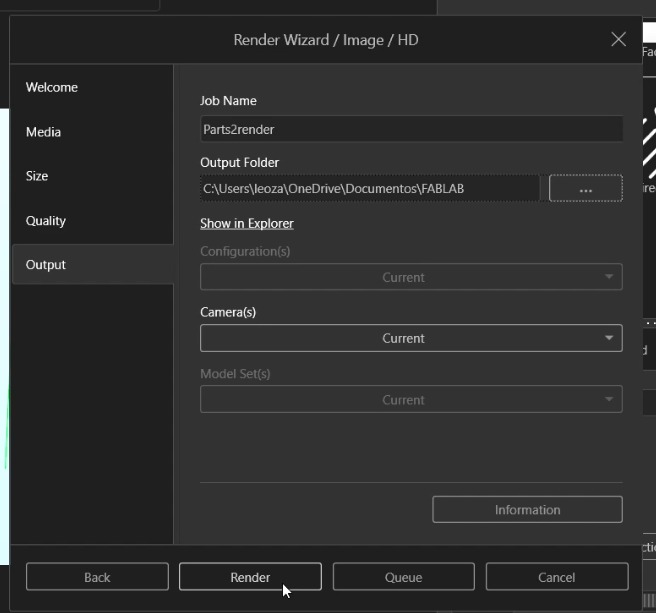
You can change the image and render quality, image format and extra things to render the part. On the last page you can choose a file name and its location, finally hit render and when it´s done you will find the image at the selected location.

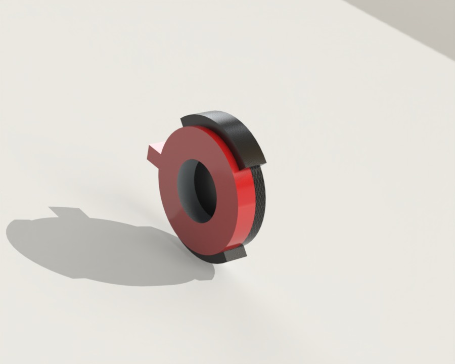
You can change the textures and lighting to improve its appearance.
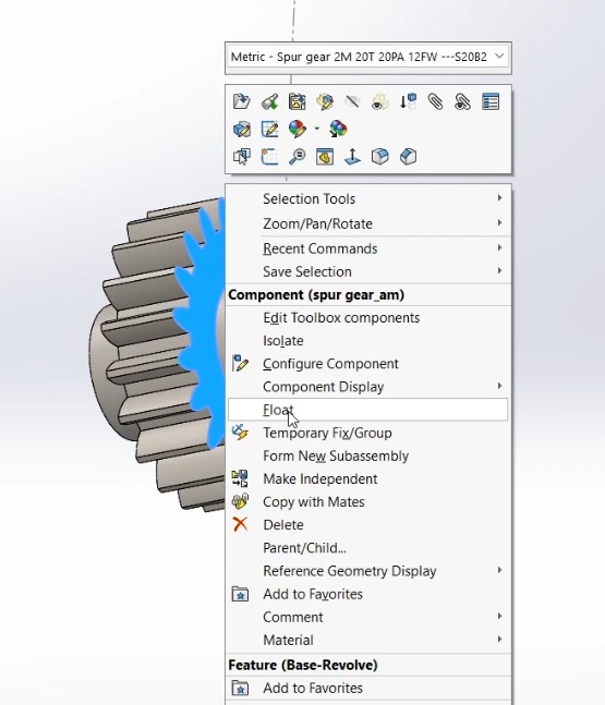
To animate a rack and a pinion we need to create an assembly. Add the components and right click on them and select "float" (This is to be sure that we can move the parts).
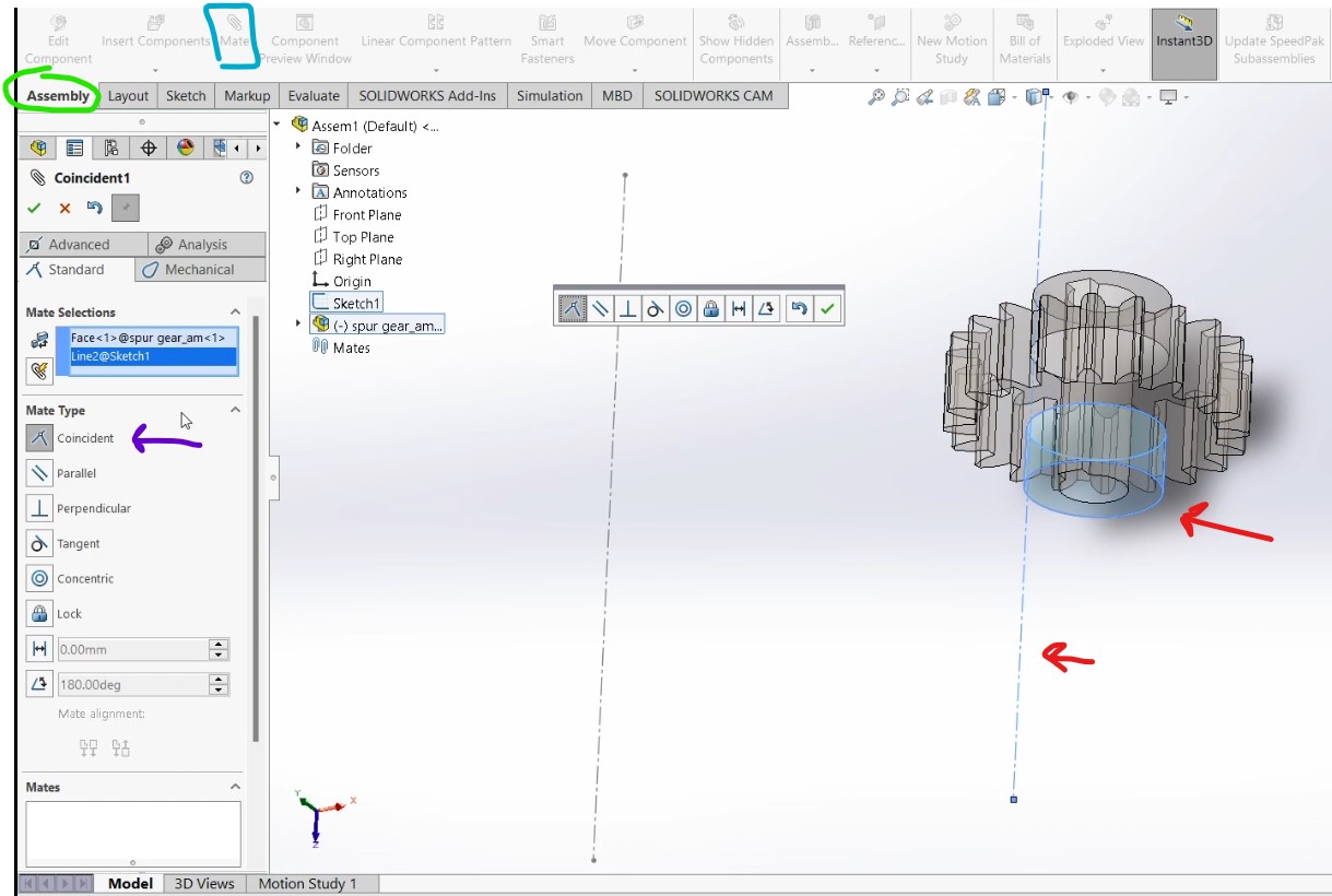
After floating the parts, click on assembly (green) select the "Mate" tool (blue) and select the centerline and a part of the gear (red). Click on coincident (purple) to create the relation
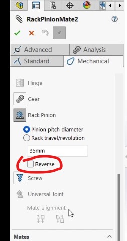
After aligning the pieces, select the spur gear and click on the sketch in green to show, then select mechanical mate (red). An the select the two lines in yellow:
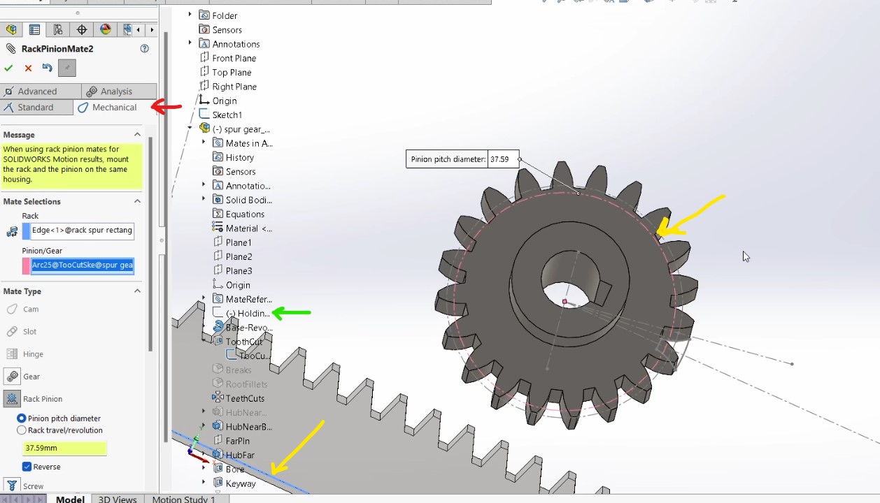
Select one of the pieces and try to see if the behave as expected, if not you can click on the mechanical mate operation on the left side and edit the feature, then select "Reverse":
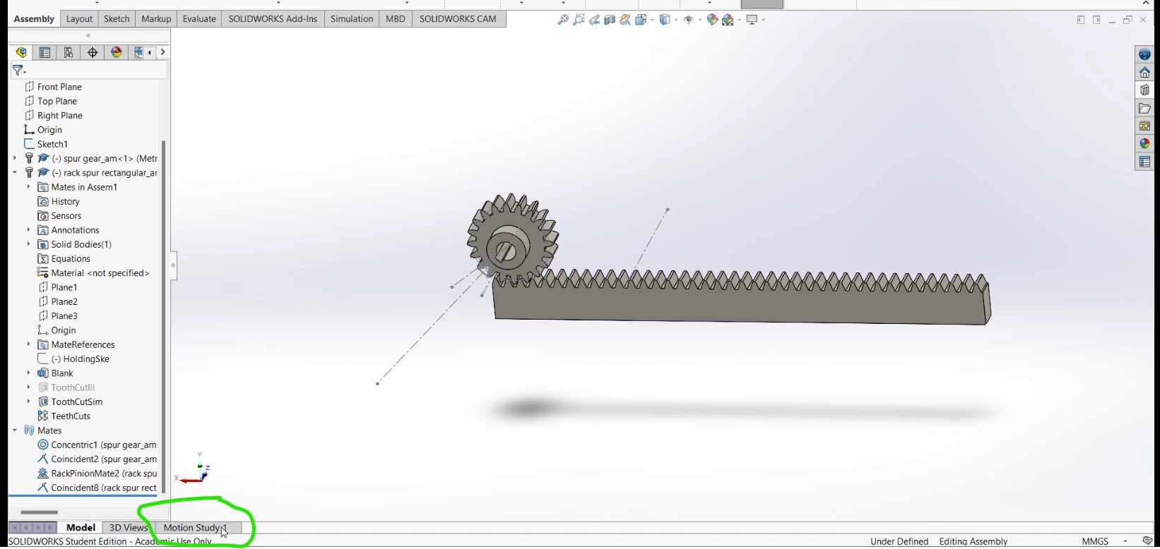
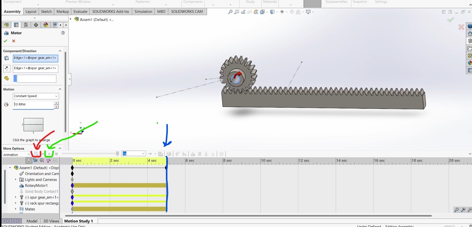
After creating the assembly, select the "Motion Study" tool (green).
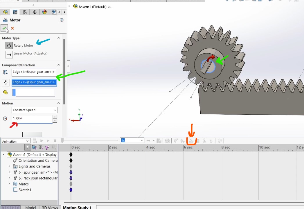
Choose the motor tool (orange). A window will show up on the left side, select Rotary Motor (blue). For the component direction select the line in green. Change the speed (red).
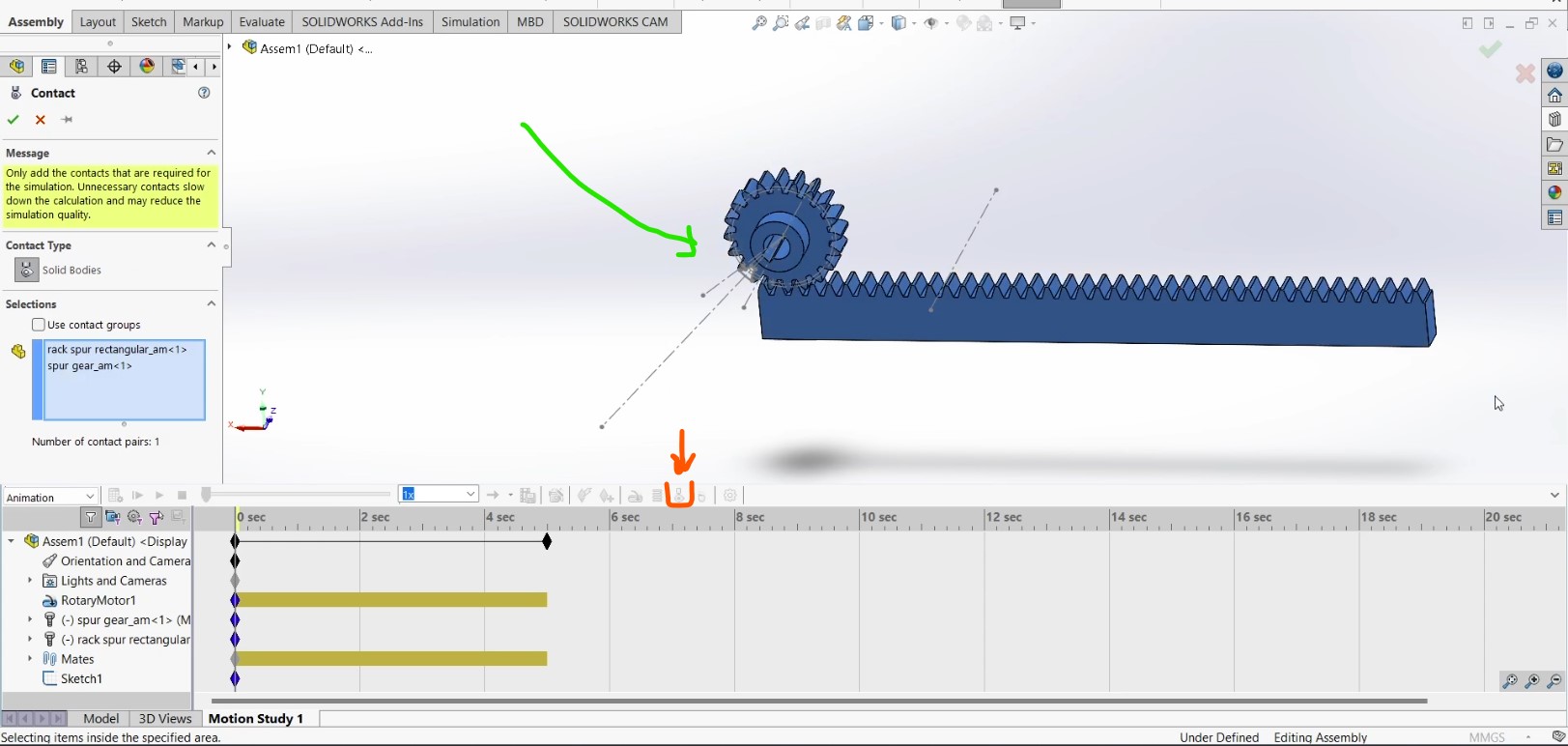
Click on the contact tool (orange), then select the two parts (green) to make them solid bodies.
You can hit the play button (green) to start the simulation, the blue line can be dragged to change the length of the simulation. When you are done you can click on the calculate button (red) to save the animation.
After saving the animation, you can click on the "Save Animation" tool (blue) and select the location, file name (red) and its format (green).
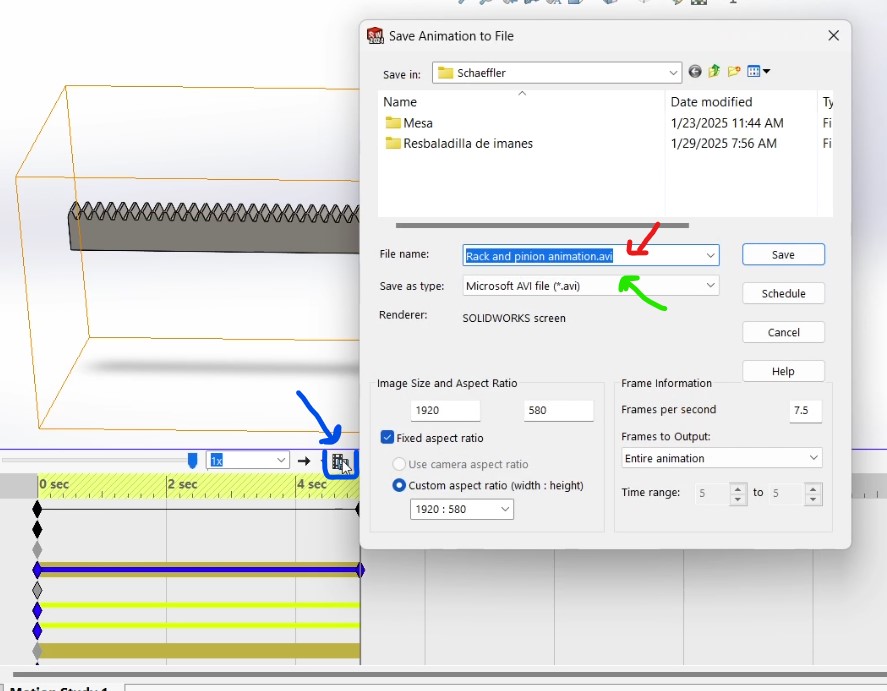
Hit the save button and the animation will be exported to your selected location.
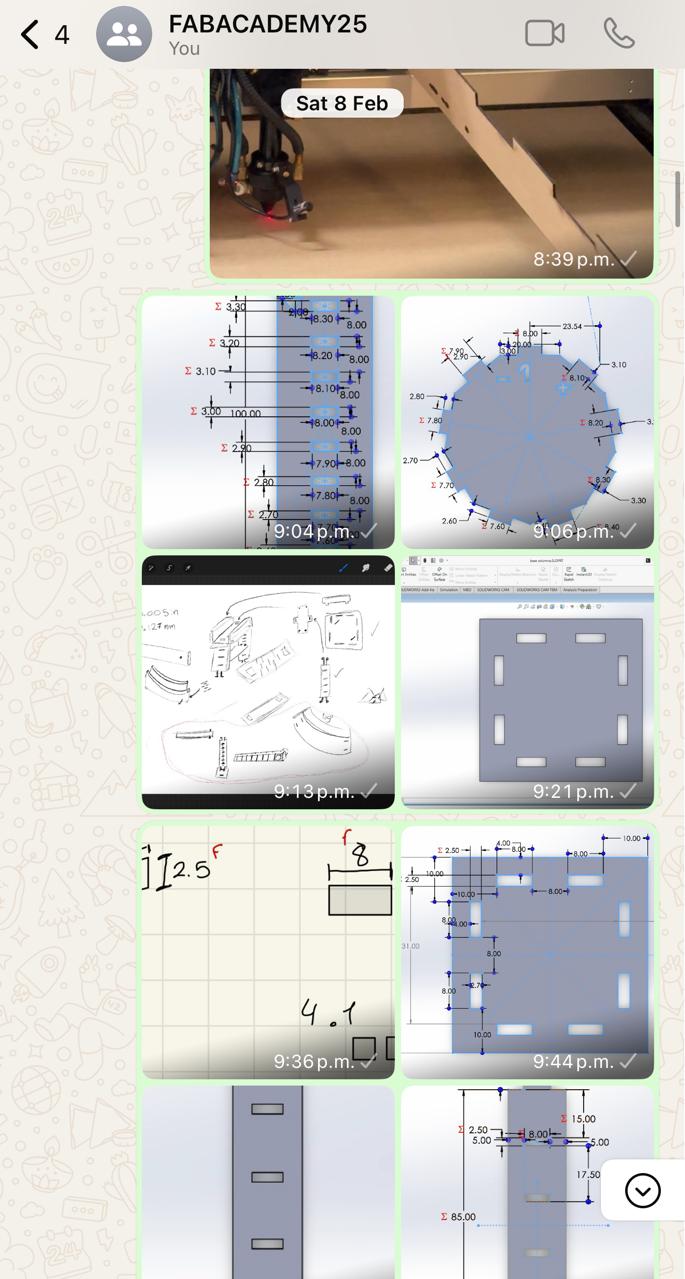
Image and video compression
You may have noticed that I took a lot if screenshots and video for this week. For image compression I´m using WhatsApp: I created a dedicated group for this purpose and I send the images to the group, then I download them to my computer.
For video compression I´m using FreeConvert . I upload the video and select the format and quality I want, then I download the video.

With these tools I was able to put a lot of images and some videos on my website.
Summary
I found SOLIDWORKS to be intuitive and useful for making fast 3D models and for animations and renderings. Fusion 360 was a bit different, but I could make different shapes that would take ages to build in SOLIDWORKS. As for 2D design, Procreate was a paper-feel-like experience to make drawings, it gave me the control to be more artistic. On the other hand, Inkscape was better for making precise shapes and gave a more professional look at the drawing. I think I will be using Procreate to sketch ideas and Inkscape for a final product.