Week 10. Output devices
But first
Yeah this are anything that the micro controller wants to make or communicate, this are usually motors, screens, heaters and stuff like that, they are usually what consume the most on the circuits so...
How much does a DC motor consume
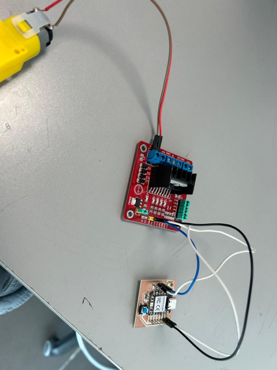
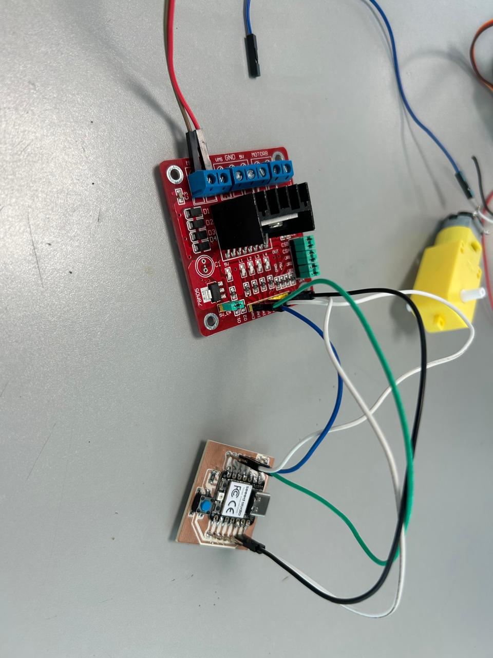
As we saw on the group assignment there is a way of knowing how much does a component consume, and it is with that usb with the screen. So I wanted to know how much does a DC motor consume with the voltage of a pin of the micro controller, so I connected the motor directly to 2 pins of the micro and tried to run the program but it didn't do anything, so I had to connect a H bridge I had and then it started working.
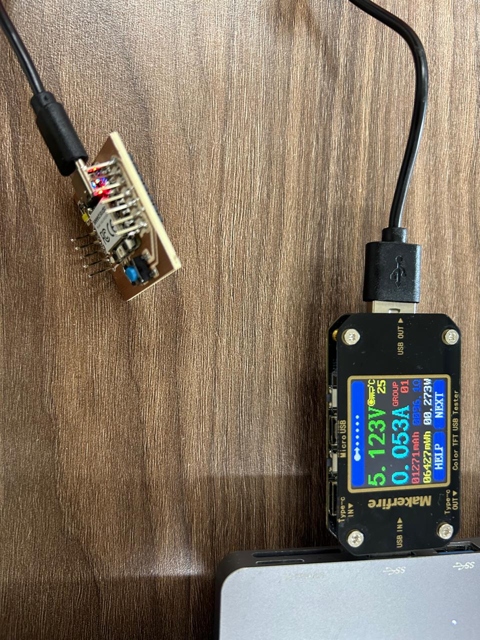
So, this is the consumption of just the micro controller
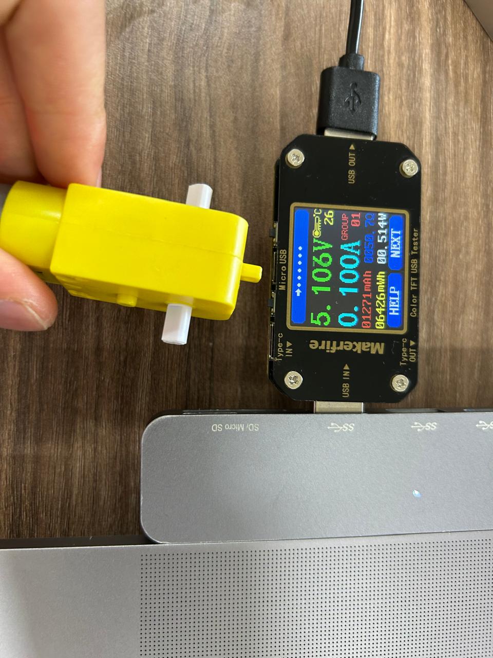
This is the consumption when the motor is connected but off
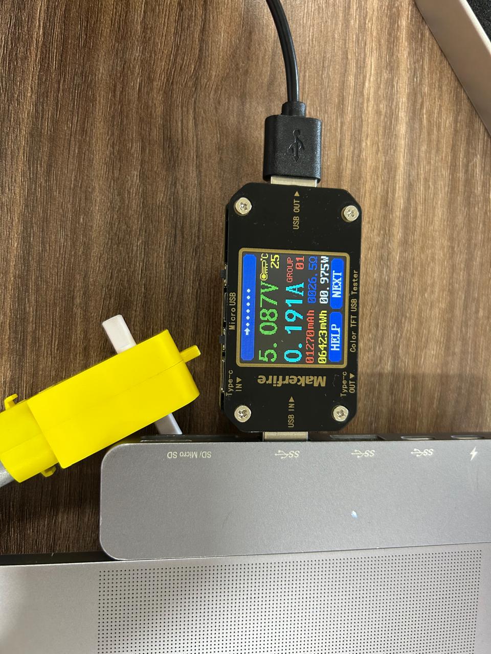
And this is the consumption of the micro when the motor is on with just the voltage the pins of the micro and a H bridge.
So, as we saw on the group assignment we have to do the following calculations P = V * I, so we obtain the data with the USB.
Power consumption while off
P = 5.1 * 1 = 0.51W
Power consumption while on
P = 5 * 0.19 = 0.95W
The board I used
My coding
So, programming a DC motor is very simple, as it only has 2 wires, positive and negative, and depending on where on connect each wire the motor will move on a direction or the other. So The very first basic program was just declaring the pins as outputs, and digital write, low or high, or on or off (with the H bridge, this should work to move the motor). You can invert the pins and it will rotate the other way. If you set both pins on LOW, or off (0) the motor will not move. But read this carefully. Never write HIGH/ON/1 on both pins Or this will blow up everything. I didn't made that mistake, but I was aware just on time to not do that. Look the examples of code and wiring
void setup() {
  // put your setup code here, to run once:
  pinMode(28, OUTPUT);
  pinMode(29, OUTPUT);

}

void loop() {
  // put your main code here, to run repeatedly:
  digitalWrite(28, LOW);
  digitalWrite(29, LOW);
}
The wiring
Working
But, is that everything?
No sir, you can also control a DC motor with analog values, for this you will need to add a new wire, which will go from a analog pin of the micro to the analog input of the H bridge.
And the code will also have a new analog pin as an output. So, the digital pins will control the orientation of the turn, and the analog pin will control the power of rotation of the motor.
Just remember, these outputs will be in a range of 0 and 255, 0 is 0 V and 255 is the maximum voltage the pins can give as an output. Obviously that's not enough and we should use a +5V input of the H bridge to work on full power with the motor,
but it is what we have. Let's see the code a wiring.
void setup() {
  // put your setup code here, to run once:
  pinMode(28, OUTPUT);
  pinMode(29, OUTPUT);
  pinMode(7, OUTPUT);
}

void loop() {
  // put your main code here, to run repeatedly:
  digitalWrite(28, LOW);
  digitalWrite(29, LOW);
  analogWrite(7, 250);
}
The files
What I learned
It is easier than I thought programming a DC motor with arduino. It only needs the orientation of rotation and the intensity of rotation.
The lcd with I2C modulo, on the other hand, is harder than I thought. I tried watching videos and reading websites, but nothing, I tried different codes, but nothing. This
lcd screen, usually use many pins of th micro controller, but it is easier and more intuitive to program with the library, however, I don't have that may pins, that's why I picked the I2C module.
but nothing, so I quitted for now, and I'm just mentioning it.