Week 7. Computer controlled machining
Hi, Still here but starting to give uo so let's make this quickly. This week is about.
yes, that machine that has a drill head and cut trough wood, we are using this machine to make
larger scale projects.
But first
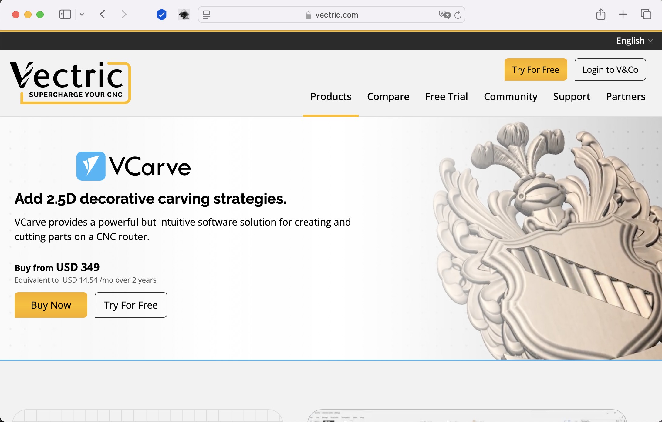
VCarve pro
This machine has almost the same bases as a 3D printer or a laser cutter. And obviously we need a software to interact with the machine, in this case we will be using:
Getting started
First
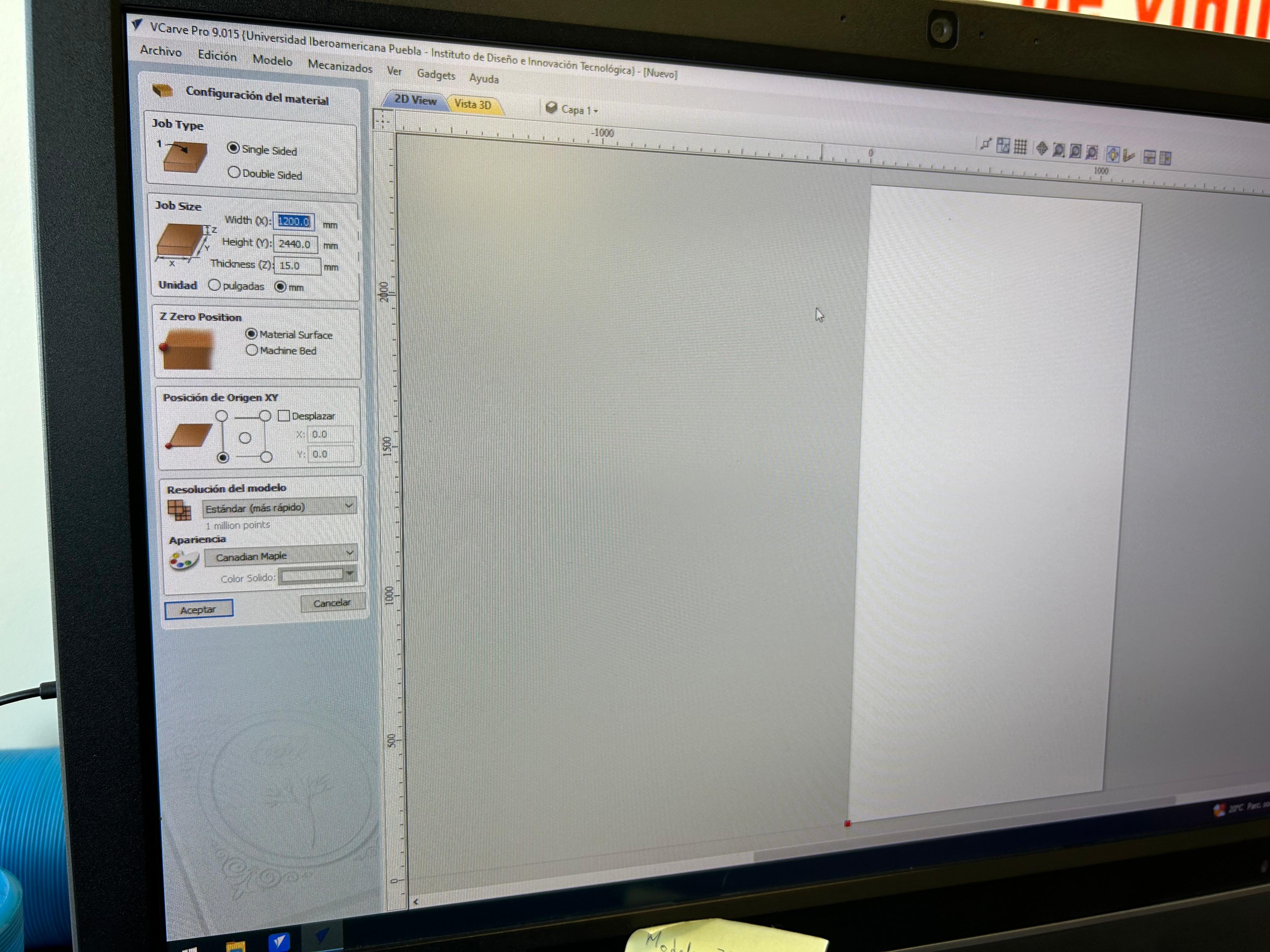
We have to tell the program what are we working with and some specifications like, the length,length and thickness of the prime material.
Then
We have to tell the machine where we want to locate our 0 position, there are two options:
- Material surface
- Machine home
To make things easy is better to set the 0 position on the material surface, to tother way we would have to guess the distances from the home position of the machine.
Then
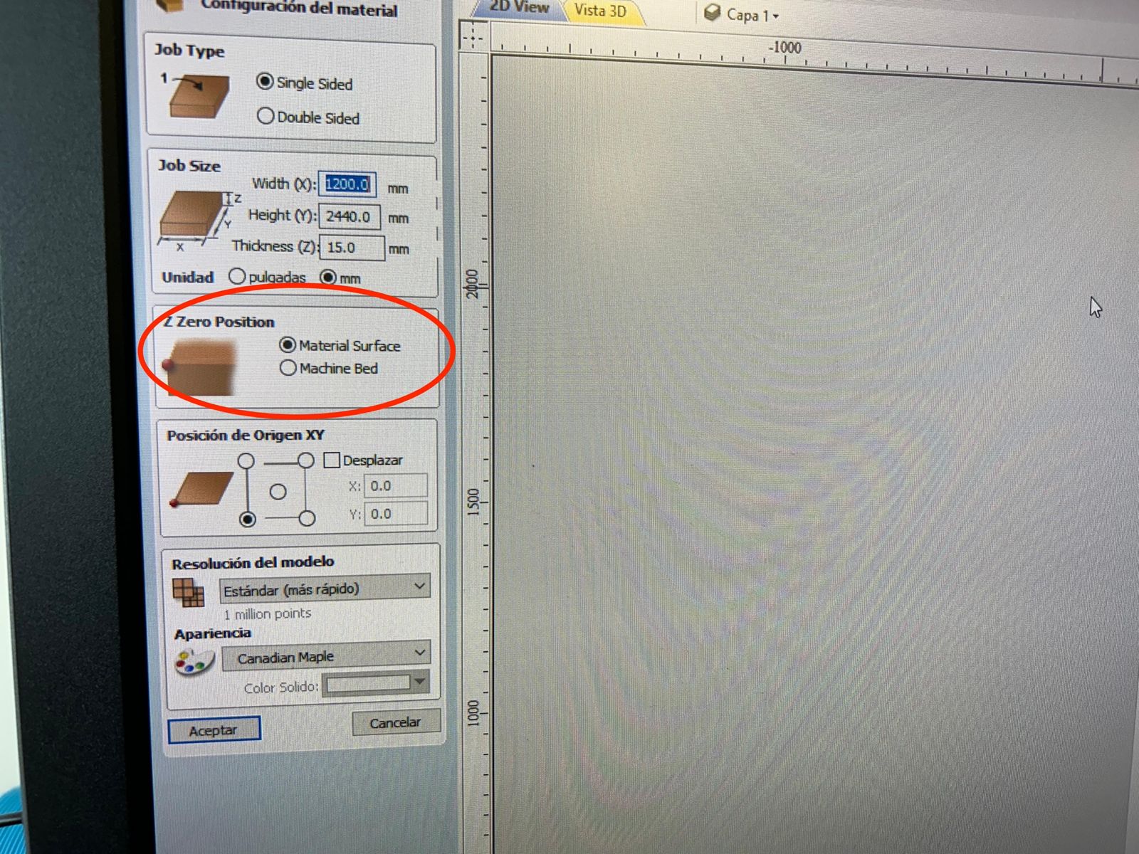
The origin, where we want the machine to star the cutting. We can set this position in every edge and the center of the material or displace this point.
It is NOT recommended to select the "center" option, just because is ver difficult to find the exact center of the material and place it. The recommendation is
to set an edge, specifically down left corner, because it aligns with the 0,0 position of the machine.
That would be ok to start working
We are done setting the material click on, accept and we will have a 2D view of the material and a 3D view of the material.
Then we can start importing the files we will work with.
My favorite file for this kind of projects are DXF, so, I will not go deeper on the type of files you use, lets use this one.
Importing the files
Just import them
Preparing the file
Once imported there is a something we have to do in first place.
Let's mention that our machine works with circular tools, so we can not make straight cuts, that's we have to make like a bone shape on thd corners.
This will, allow you to get closer to a corner ad assembly some pieces.
Dogbones
There are a few steps we have to follow in order to make this dog bones
- First we have to make all the lines of my piece a single line, for this we select connected lines and use the Join lines tool.
- Once we have the piece as a single line, we have to look for the dog bone tool on the left side menu. In spanish it is called "chaflán". In the options it gives us we are looking for the "cabeza de femur" option, then we have to give the diameter of the cut. This measure is the half diameter of my tool, for this task we are working with a 14 inch tool. So in this case 1/8 take it to mm.
- Clock on each corner to create the dog bone on the piece
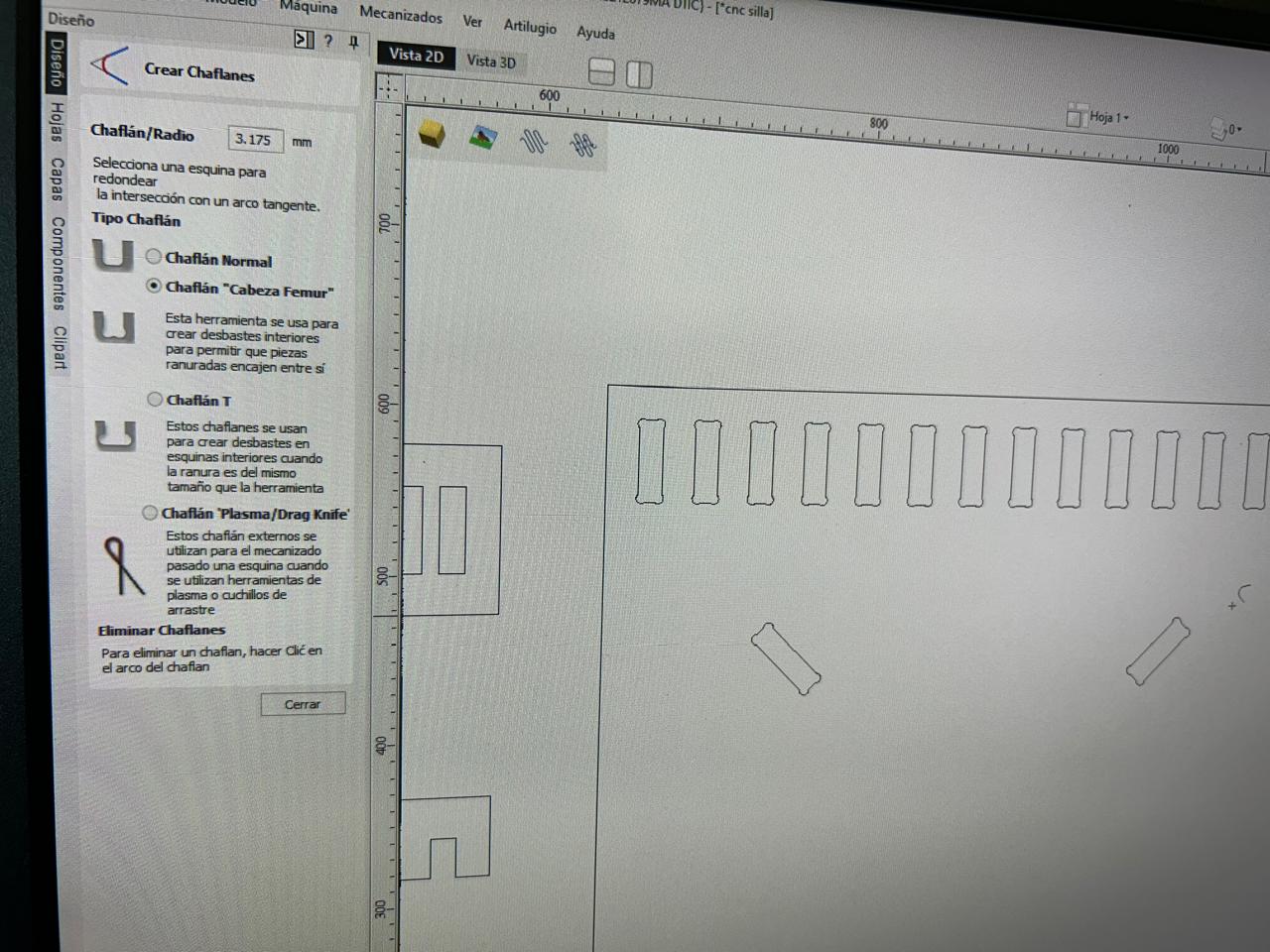
NOTE take into account, which edges should have this extra cut, every inner edge or assembly edge. Once done selecting the edges let's go to the next step.
Every day tools
In case we need it, we can duplicate the pieces and move, scale, rotate it, etc
Preparing the job
Let's tell the machine what que want to do, starting with the
Selecting a task
There are different types of task to start, we can found then on the right side panel of the software, or just look at the image.
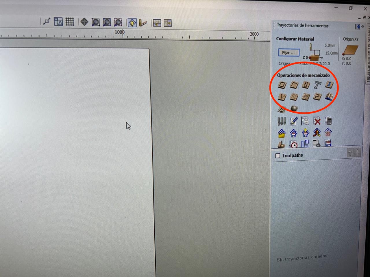
Within this options, The first option, and the most used tool os the "perfil" I don't know how to say it in english, this is literally going all the side to cut the edge of the material.
Once selected, The first parameter is depth, where I'm I going to start and where do I finish (talking about depth). The final depth should be the thickness of my material, however it is recommendable to go a little deeper just
in case there is a irregularity on the material and make sure it goes completely through the material.
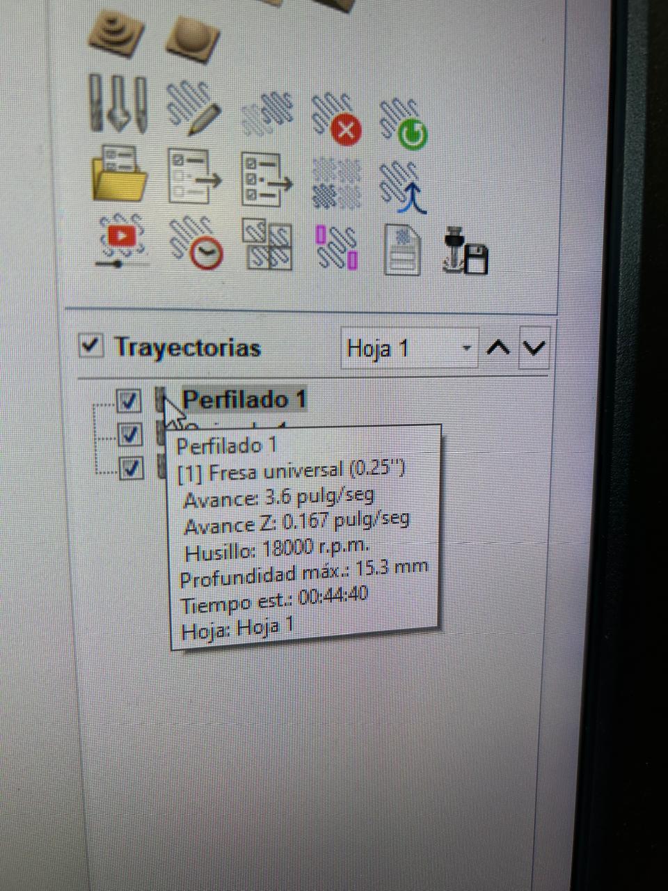
Selecting a tool
In the second menu we have to select the tool we will be working with, there are some default tools but we can create our own tools.
I don't have to, but if we select the edit option we can set some important parameters, like:
- units
- size
- depth
- r.p.m.
Special mention to this one because if we set low r.p.m. we can set fire to the machine, and if we set high r.p.m. we can also set fire to the machine, so there are some tables that will tell you the required r.p.m. for each size of tool.
So 18,000 r.p.m. are enough for a 1/4 inch tool. - Steps
another special mention to this one, the case as the r.p.m. to much = fire, to slow = fire. There are also tables to set this speed, and the tables we can go from 3.6 in to 4.8 in. 3.6 Is a good one and 4.8 is an aggressive one. As we are getting into this, we will use 3.6 in
- down speed
We can leave this parameter as default.
In my case I just selected a default 1/4 drill bit because that's what we had, so click on it -> select and right bellow the initial menu a menu with the selected tools will appear. Each tool will be linked to a specific task previously created.
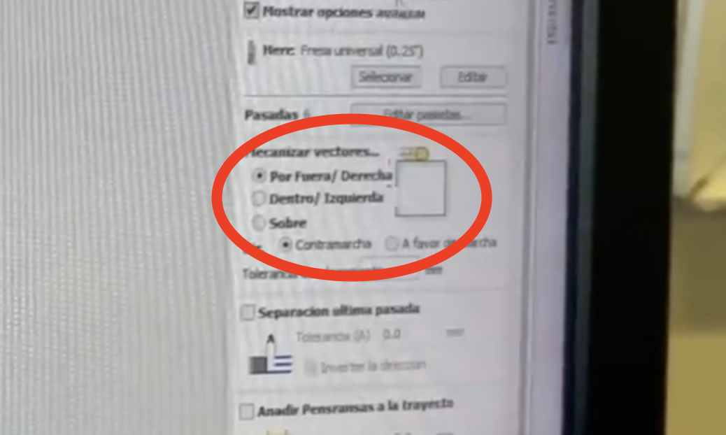
Indicating the path
Going to the next step, Where do I want the tool to go through?
Here we have 3 options,
- Outside/right
- Inside/left
- over the line
In the kind of project we are working on it is not recommendable to select the "over" because it will cut material we need. For the outside lines, select the first option and for the inner lines select the second one. That's the easy way.
Supports
The last part of the cutting process we have to create some "pestañas" so the material doesn't ends on the other side of the lab and no one results hurt. This things are little bridges to keep the piece in it's place, so make sure this are slim enough to cut it with our hands. So the recommended measures are: depth = 1.5 mm and length = 5mm.
Activate the "Pestañas"
Place them manually
Here you can see how to add "pestañas" manually, so you have to place them one by one on every piece you want to set
Place them automatically
Or you can ask the program to place them for you, however check them because this "pestañas" on the edges are not recommendable, always on straight lines.
Click on accept and calculate and accept.
And in this video we can see how we can add them automatically, just click on the option, write how many do you want per piece, and click "ok" it will create them automatically
but always remember to check them, because there are places where they doesn't work at all, like when they are connecting to a very thin piece or to a piece that will be removed form the main piece.
Once the machine place them you can erase them and add them manually by clicking on them and where you want them.
With this basic parameters we have selected what we want the machine to do, how we want it to do it, and with what. Basically done, however there a few steps left.
What happened next?
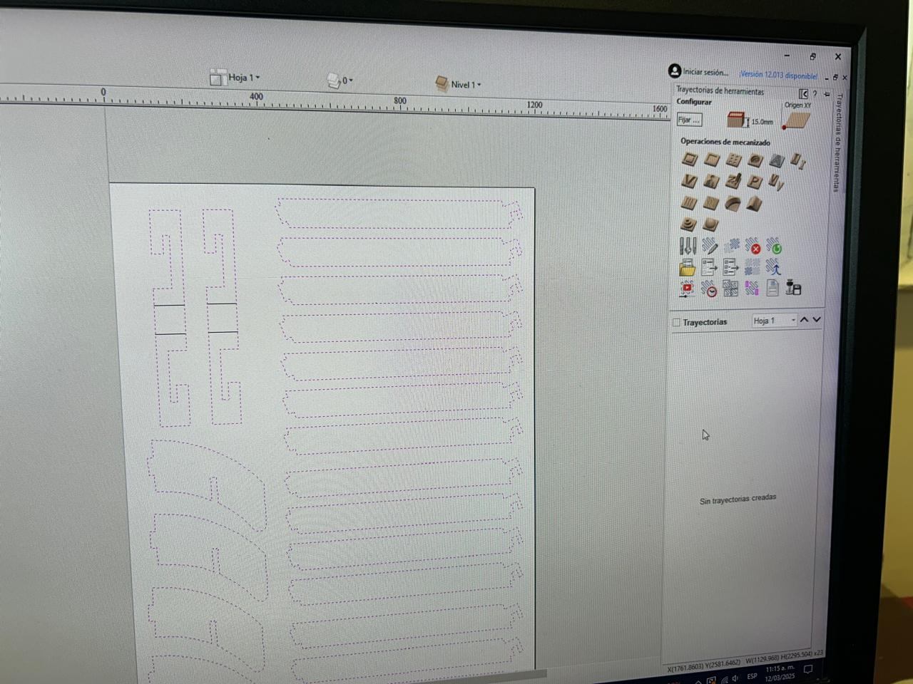
Once done with the previous step it will just open the 3D view with some blue, green and red lines.
-
Blue lines
Where the machine will cut -
green lines
Where the machine will go deeper -
Red lines
The machine moving in the air
So we can preview what will it do.
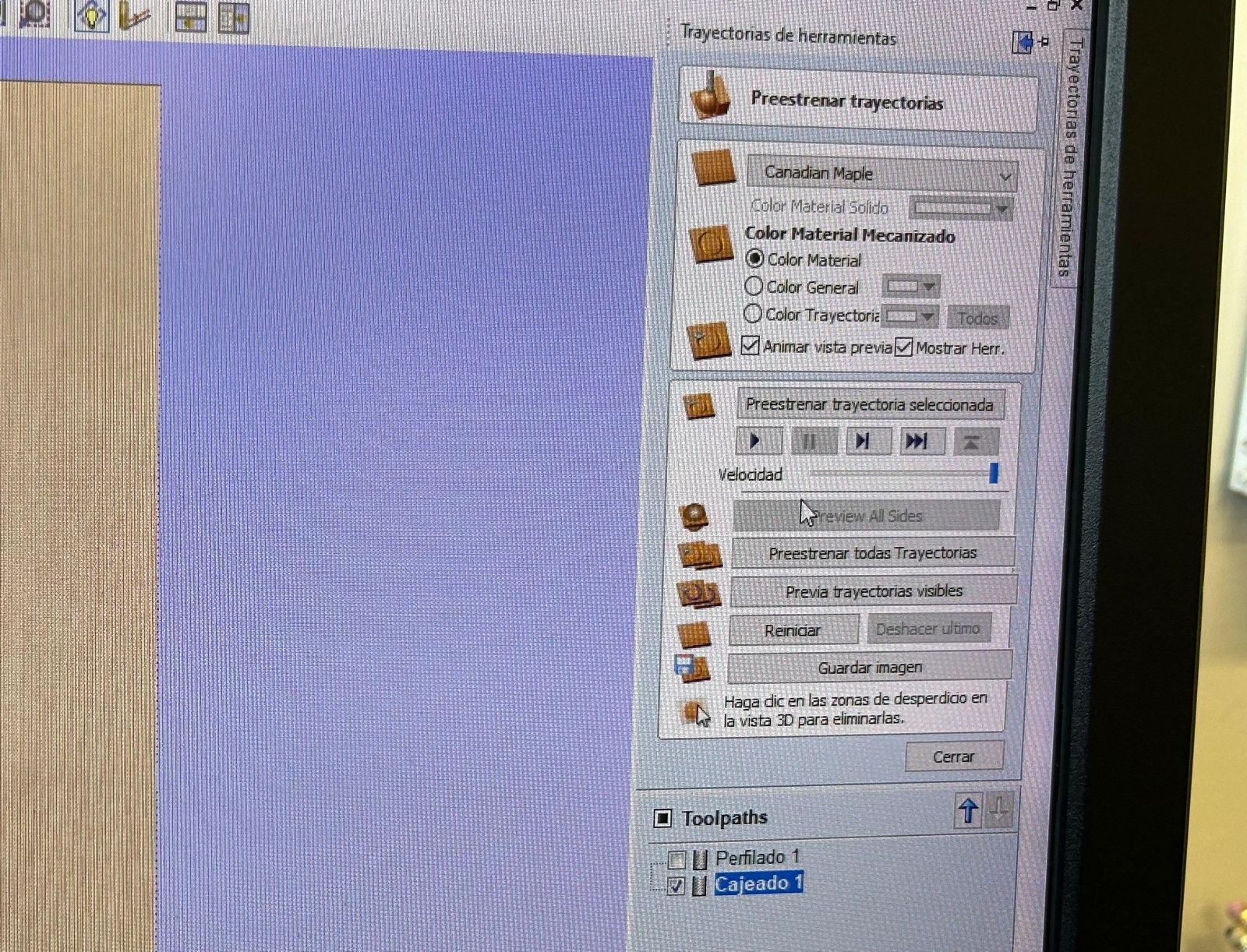
Always click on the play button, it is a little slow when previewing but you can move the slicer right bellow the play button all the way to the right so it makes it real quick. While the animation is running the material it will actually happened on the material so you will literally see how will the machine do it.
And next?
We have to select the left lines that will have the same parameters and repeat the previous steps.
Infilling the cutting
At least that's how I would call this tool, I don't know the name in english.
This as the name says, infills the cut, the second option, literally the box.
Here we have 2 options, the first one and the second one, ahahahahahahahahahahahahahahaha
No.
The first one will make concentric forms until everything is filled.
The second one will make straight lines until is completely filled.
NOTE, don't forget to set the depth.
What else?
Many things, explore them by yourself
Is that it?
Noup, we have to export the file, just clock on the button: save trajectory and select a postprocessor, this will translate what we made on the software to instructions the machine can understand
NOTE. in this fablab there are 2 machines, and each one has different things let's call them the black one and the red one.
For the black one we will use: MACH2/3 ARC in mm/s For the red one, we don't know. Once selected the processor, save the trajectory, with save everything in a single file. (In case everything is cut wth the same tool size.) If we hav to change tool, select the trajectories with the same tool and save them as a file, select the other trajectories with the same size and save them.NOTE, the file will be a txt file, where every line has commands like
-
The piece number
N... - The type of movement
-
Coordinates
x, y, z -
Speed (G numbers)
The type of movement, there is a quick movement, angular movements, and there are more. - Depth
- Etc
Let's go to the machine
The machine is an Asia robotica
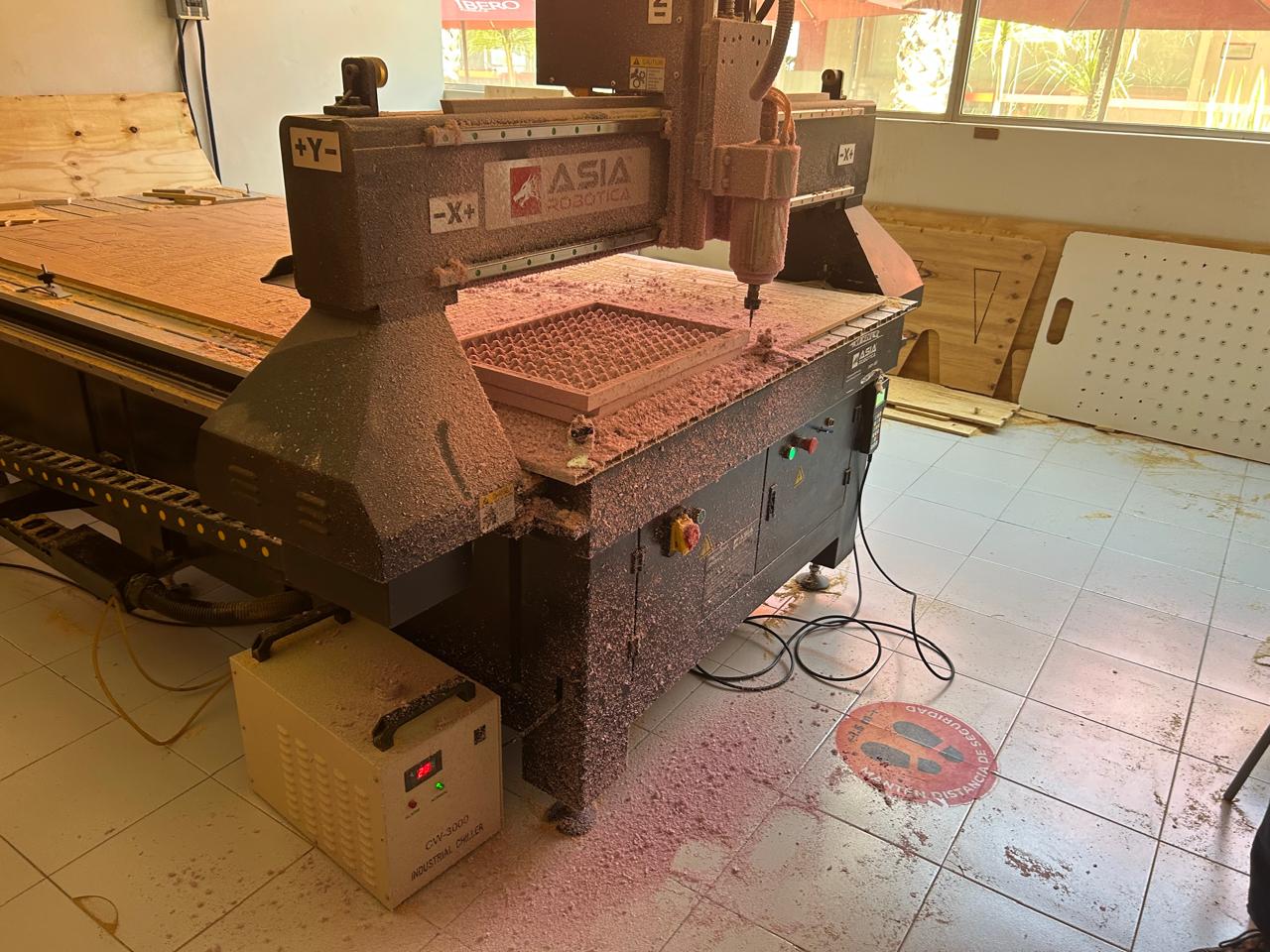
Honestly the head was bigger than I thought, and it was easier to change the nozzel than I taught.
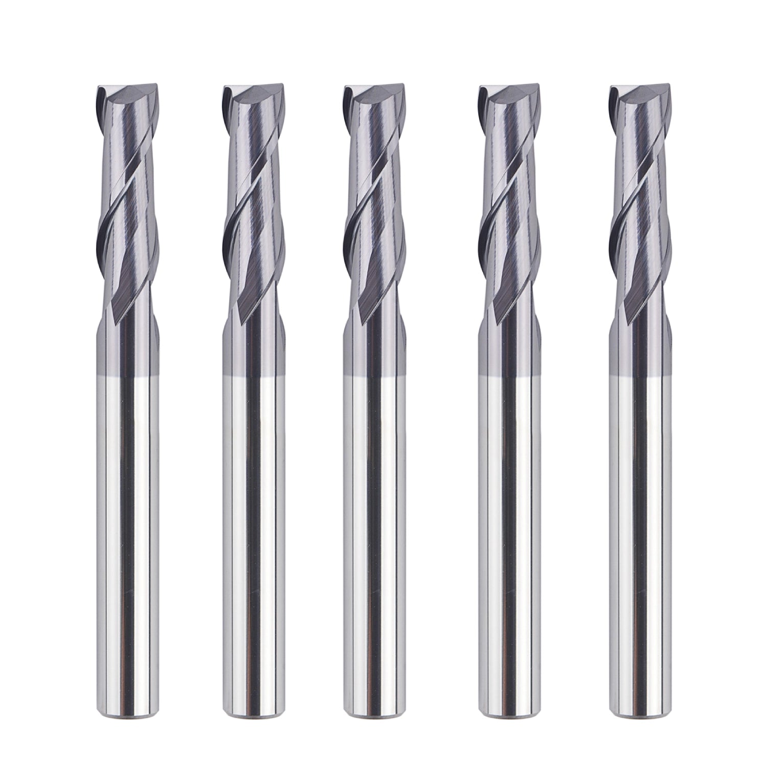
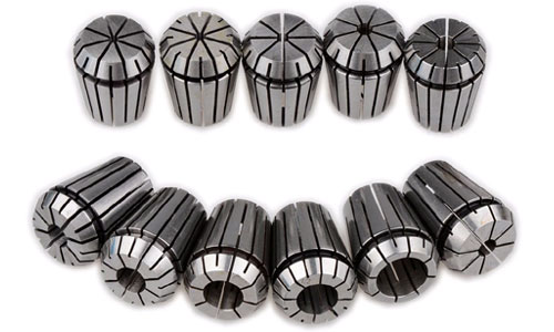
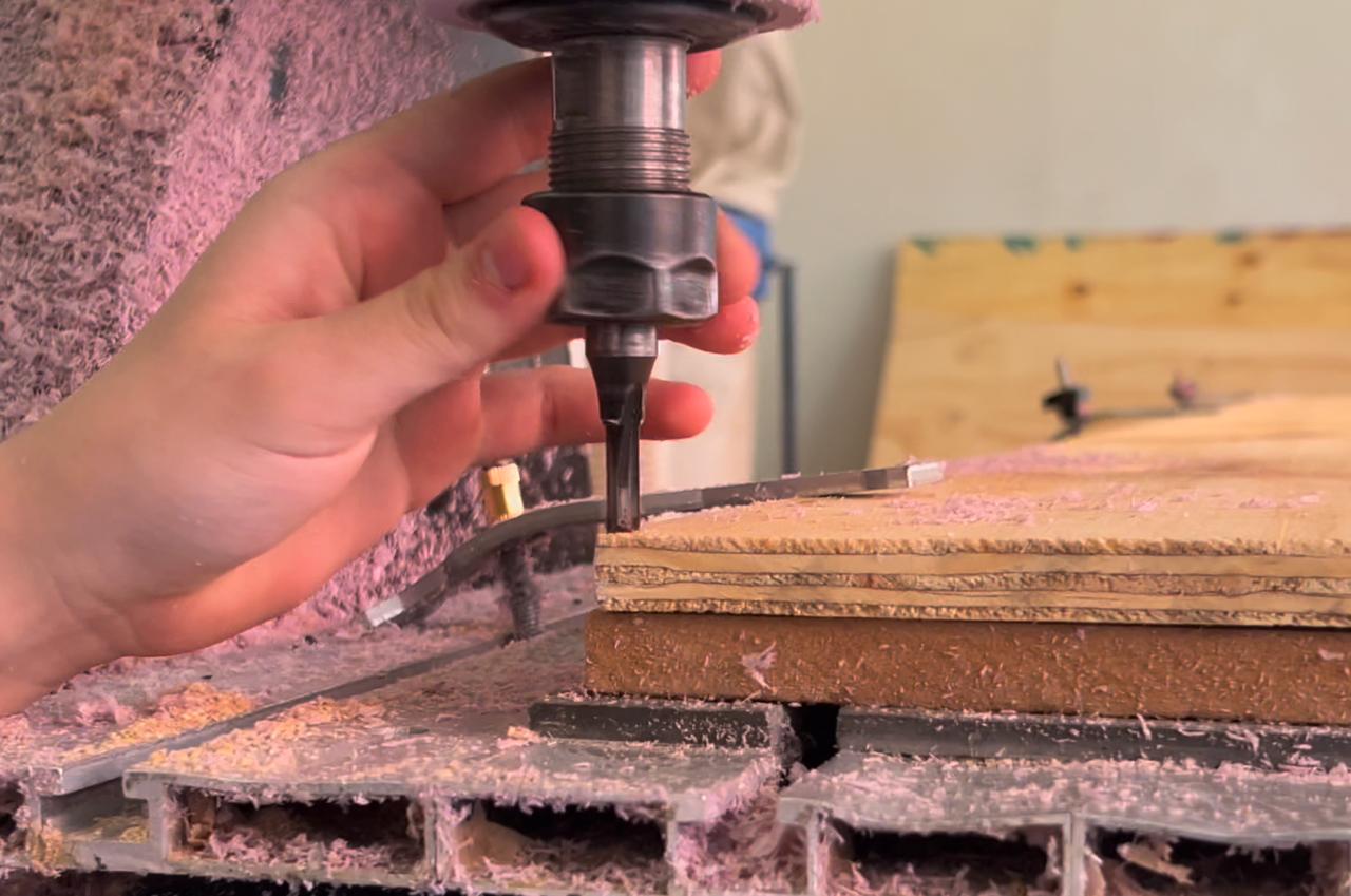
The tool
We used a 1/4 drill with 2 flutes, this means the diameter and the amount of "cut spikes" of the drill. They looked something like this.
May be this is in the group website but I have to mention it, the way of taking out the drill is with two wrenches, the head has the spinning cylinder and the support of the drill, you have to position the first wrench on the spinning cylinder to stop it from rotate, and with the second wrench, take out the drill and the drill holder.
Note, make sure to hold the drill before it falls, because it might break
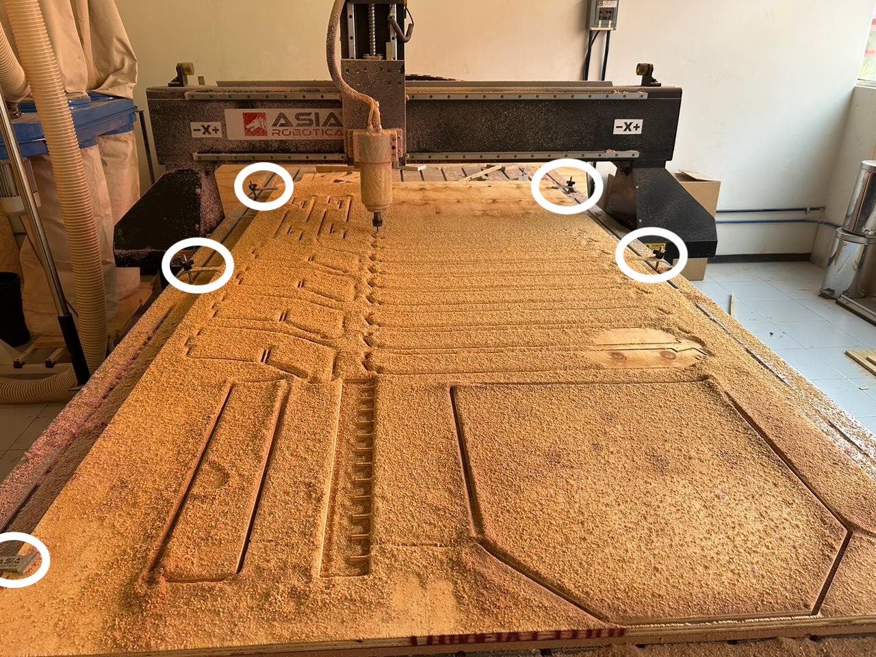
Starting to cut
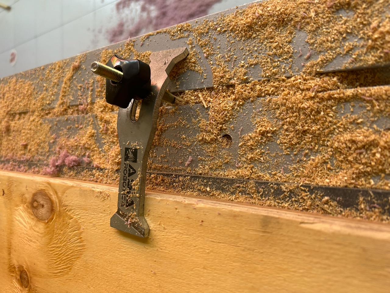
We already have the file in a way the machine can read it, we have to go for the material and place it on the bed of the machine. To secure them there are a metal pieces on the sides of the bed
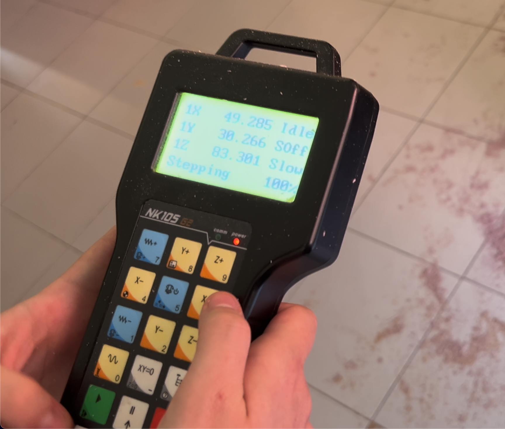
Configuring the machine
Perfect, now we can configure the machine, for this we have to turn the machine on by releasing the emergency button and push the green button next to it.
Just like in the video, to turn it of just press the big red button.
Once clicked the buttons the machine will start thinking and it will show a question on the screen of the control.
Set the origin on the machine
When we turn on the machine, the first thing it will ask us, is if we want to move to the set position, make sure that nothing is on the way
and say es to go back to the last set origin on the machine, say no if you don't want to keep on the default position of the machine .
If you say yes it will go all the way front, and it is a quite slow process so, be patient.
Now, with the axis buttons on the controller we have to move the machine, to where we want our origin make sure to make it carefully,
so you don't brake anything. Another thing to take keep in mind is that we have to set the origin of the machine in the same place where
we set the origin on te software and at the same height we set on the software, so in my case I have to place the machine on the left down side
of the wood and with the drill touching the surface of the wood. Then we can save the coordinates.
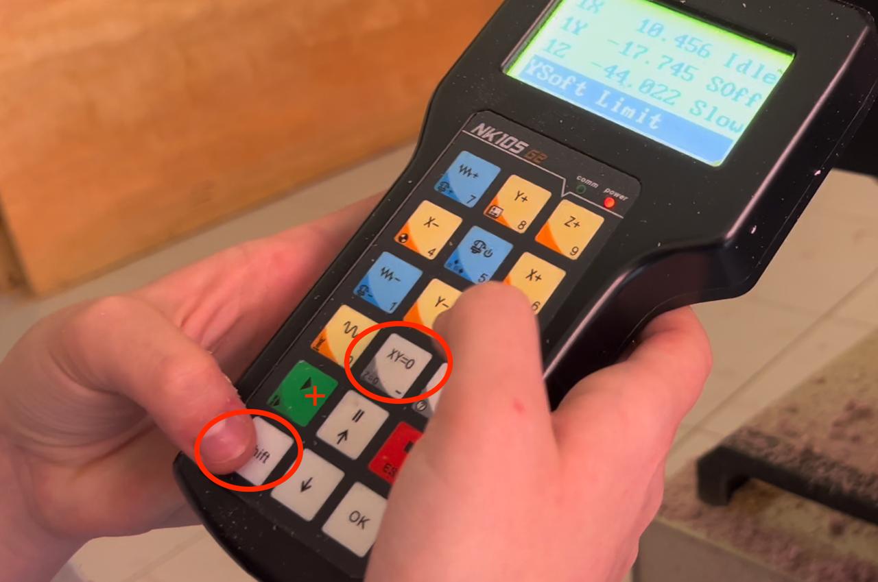
Note, the machine has different kind of movements a continuous movement (jog), and stepping movement (step), you can change between then by clicking the "shift" button.
To save the coordinates we have to click the button "xy=0", and confirm the action.
And to save the Z coordinates we have to click the white buttons "Shift" + "xy=0" and confirm the action.
Copy the file to the machine
At this point we have the files on a USB so we just have to connect it to the usb port on the machine, take the control and look fo the control and click on the following button.
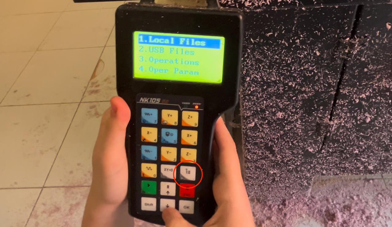
The issue here was that for some reason the machine only accepts certain USB's or old USB's so I just changed the USB to one that the machine could read. and that's it. Once copied, you have to click once again on "files", this time go to "local files" search for your file and click on it to start. For this point you should already have checked everything is in ti's place and without the provability of being broke.
Let's take a few seconds to watch the machine working
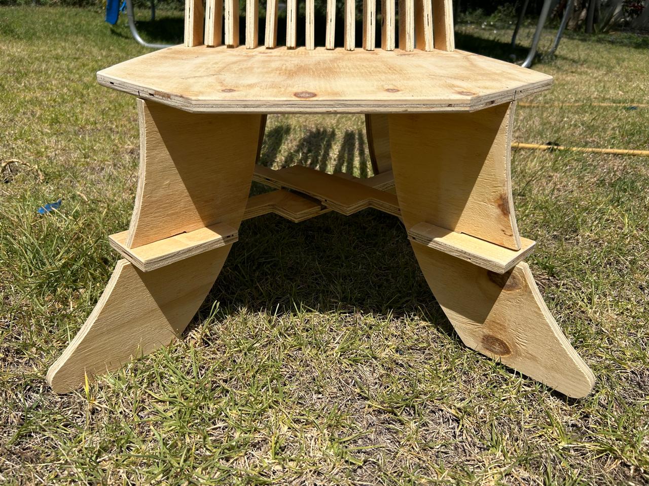
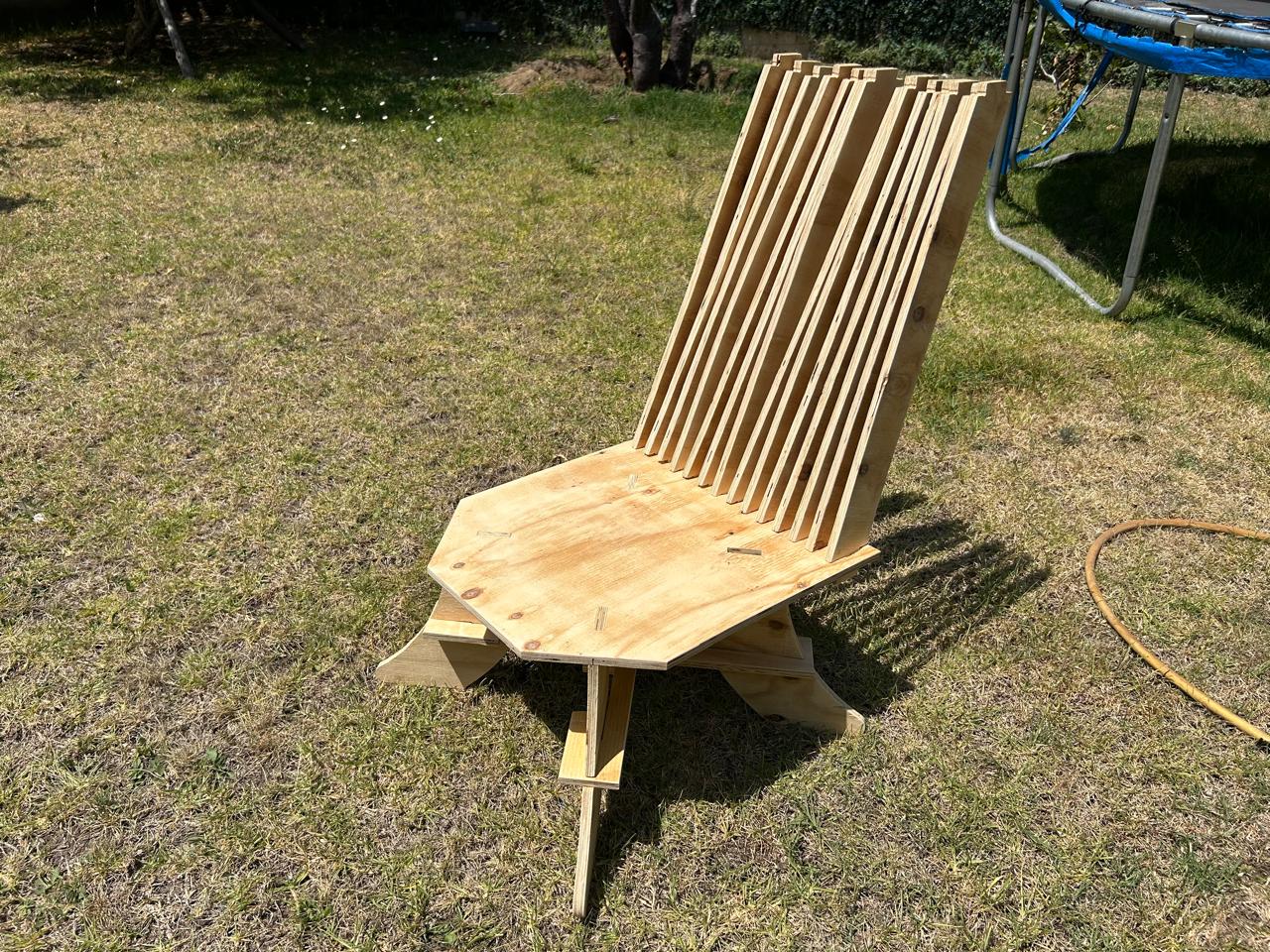
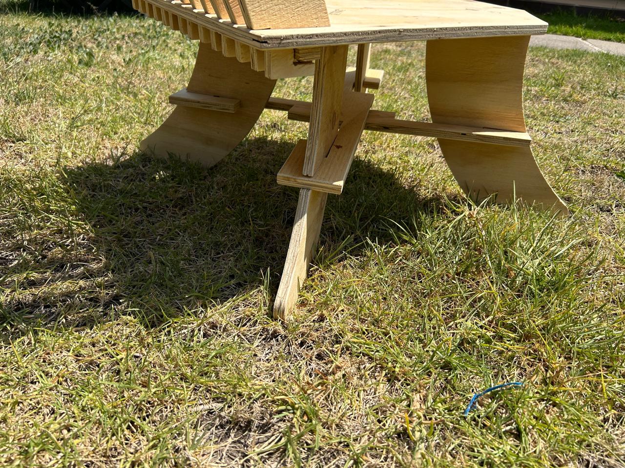
The final product
The files
Here is a .zip with the parts of the chair on DXF
Here is the carve file
Here is the cnc file with all the trajectories
What I learned
First of all, on Vcarve ALWAYS run the preview of the cut, if not, the machine will not do the cuts. So always preview.
Then, as you add cuts to your program on Vcarve there will be appearing layers on the right side of the window, this layers are not the order of the cuts, As on the laser you can set what to do first by placing those layers,
Not here, the process should be, inner cuts and then the edge cuts. And you can set them by exporting the layers on different files and follow the order manually.
Then, ON the machine, As this machine has metal plates to fix the wood on the sides, you have to take that distance into account, I set the origin of the machine very close t the wood edge, and the drill broke because it crashed with the fix plates.
So remember, on the software, set the pieces as close to the origin edge as possible and leave some space on the other side for the plates. Now, on the machine set the origin of the machine
OUT of the margin of the plates, this way everything will be alright. The just keep an eye on the machine if it is getting to close to the edges you can pause it or stop it.
I also had to add, there a design error on the chair, because most of the weight is on the mach side of the chair, so the front part goes a bit up. The solution is add some weight with rocks or anything heavy to bring the center of mass more the center.