Week 4. Embedded programming
Helloooooooooo, still here, this week was about microprocessor programming, I thought it was easier, and it is easy, is just that is different from programming just in python. There are many things to know to run a program. But first...
Before starting
Check this group website for more information
What is a micro controller?
A microcontroller is kind of a head of a machine, is the thing that processes all the given information. This things have 3 main things, the code, the sensors and the actuators, within the physical part (sensors and actuators) there is every electronic component, and this electronic components work according to the given code. The code are the instructions of what to do with every connected component. The code can be written in many languages such as, micropython, arduino, c++, rust, etc. Also, is important to mention that there are many many MANY types of micro controllers, from arduino, raspberry pi pico, tiny, and many many other.
NOTE, is important to read the information sheet of the micro controllers to know what does it offer and pick the one which more adjust to your necessities.
NOTE 2, many micro controllers can be programed with different languages, not using 2 languages at the same time, you have to install the language and if you want to change language you have to desinstall the language and install the new one and so rewrite the hole code.
The micro controller I chose
Well I didn't picked it but is what our fablab will give us: raspberry pi pico
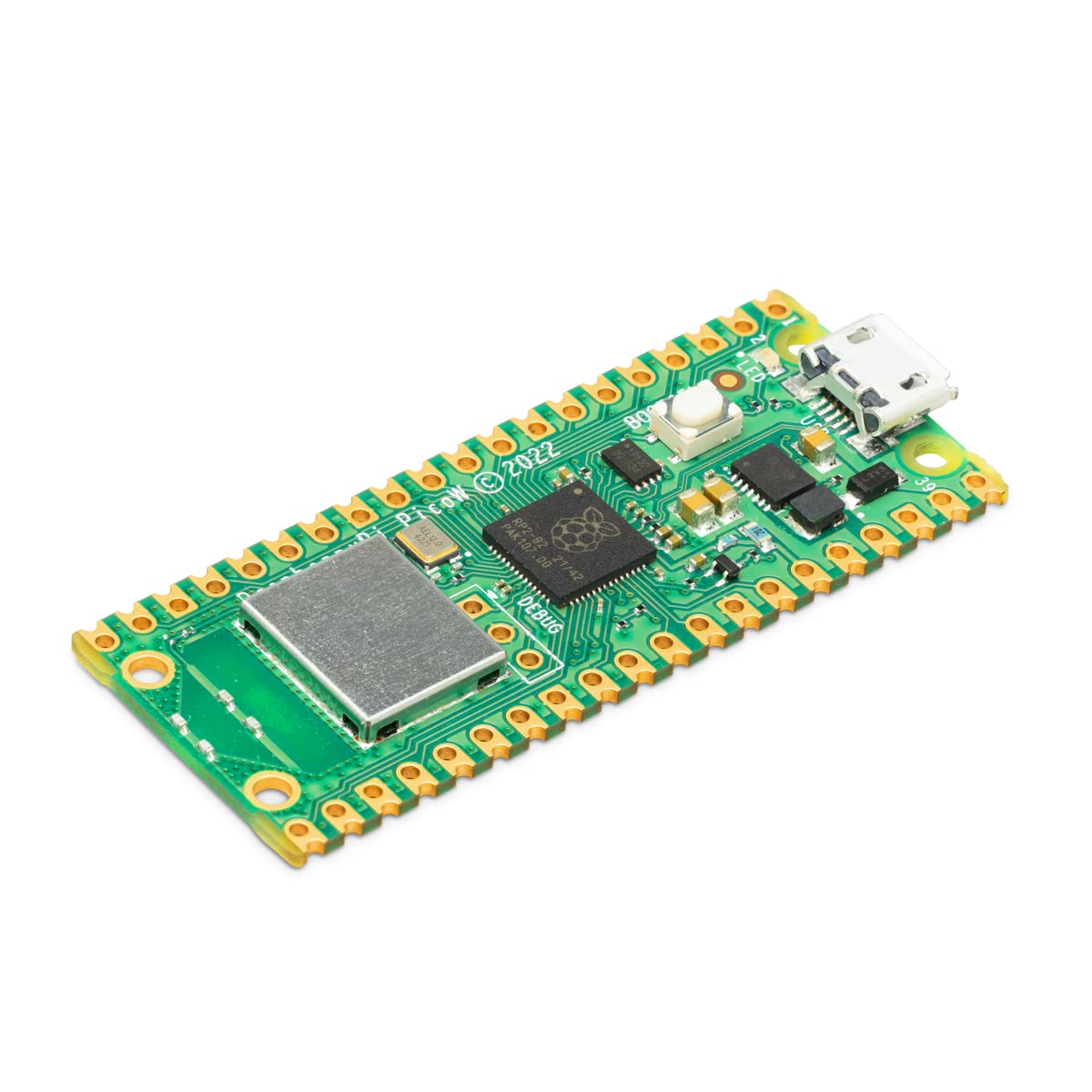
To pick the right micro controller we have to read the data sheet, in this case this link is from the pi pico, some important things to look at are:
- Type of power source
- Number of outputs
- Able memory
- I still don't know that much
This one has a RP2040 micro controller, 2MB of Flash memory, SRAM of 264kB, Operation voltage of 3.3V and 5V, 26 digital Pins, The first steps are:
- Pick the right micro controller
- Install the language on the micro controller
- Select he pins for physical electronic components
- Write the program
- Make the physical circuit
- Test
How to program a micro controller?
Now it's time to start programming, here is very important to keep in mind the libraries, this are like packages of information
that allows you call some predefined commands with specific functions and make the programming process a lot easier.
In my case I just used machine and utime.
machine
- Allows you to call the inner functions of the micro controller like: Pin and timer. Pin means literally to the pins of the micro controller, where the electronic components are plugged. And timer calls for the timer of the micro controller and allows you to make interruptions.
utime
- utime means micro time, this library is mostly used because of sleep this command literally turn "off" the hole micro controller for a specific time.
Once done with the libraries the second step is to declare your variables and pins (which are also a variable). The led is the easiest one to declare because you're just declaring an output at a certain pin.
led = machine.pin(0,Pin.OUT)
This is a led = call the class "pin" form the machine library (led is on pin 1, and this pin is an output)
But for a push button is a different story, you hav to declare it with a push down or push up line. This line will tell the micro controller in which position start the pin, for pull_DOWN it will start on a low position (0) and once pressed the button it will change to UP (1). For example:
boton = machine.Pin(0,machine.Pin.IN, machine.PULL_DOWN)
This is a button = call the "Pin" class of the machine library (this button is on Pin 0, this is an input, and start this button in LOW position)
For example:
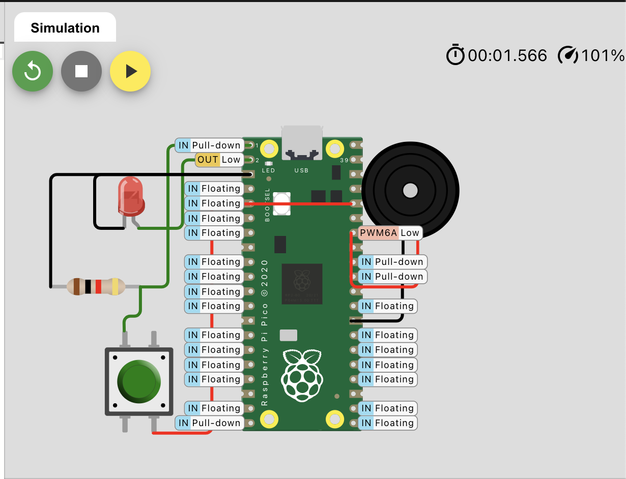
This image shows the state of the pins we declared, the led is an output, the button is an input with pull-down resistor.
Important concept
PWM means "pulse with modulation", and this is basically a way of controlling pulses. Think about it like a every day up and down continuos signal, 0 and 1. Where the amplitude will be the voltage (just off or on), the period is the complete cycle, and a cycle has an up section and a down section.
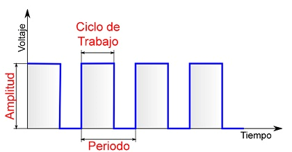
This kind of pulses are defined by the percentage of up time (called "duty" when programming). So for example, if we have a period of 1 second with a max voltage of 5V and a duty of 50% the led will turn on 0.5 seconds and will turn of for 0.5 seconds. A duty of 30%, the led will turn on 0.3 seconds and turn of 0.7 seconds.
What I did
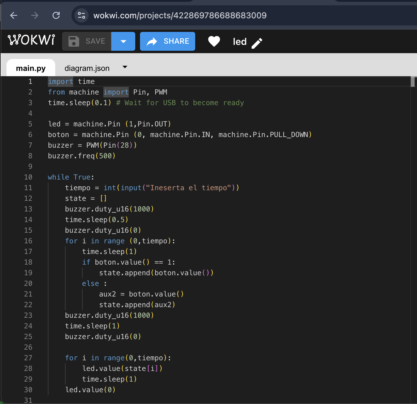
I wanted to do a lot more things but, I couldn't JAJAJA SAD, so I ended up doing a "copy" program. This program asks you for a period of time, activates a buzzer to tell the beginning of the data capture, and you have to press a push button whenever you want within the given time. When the time is over the led will turn on the same time and order you pressed the button.
NOTE I used wokwi to make this simulations, this website has arduino, pico pi, ESP32 micro controllers and many languages like, arduino, micropython, and rust.
NOTE2 I used micropython, I've worked with python before and is one of the easiest programming languages.
The logic behind the code
So, I heard the micro controllers have an integrated timer, and I tried using that to make my program, how ever I couldn't find any tutorial that explains me how exactly that worked. I asked my local instructor and taught me an easier way.
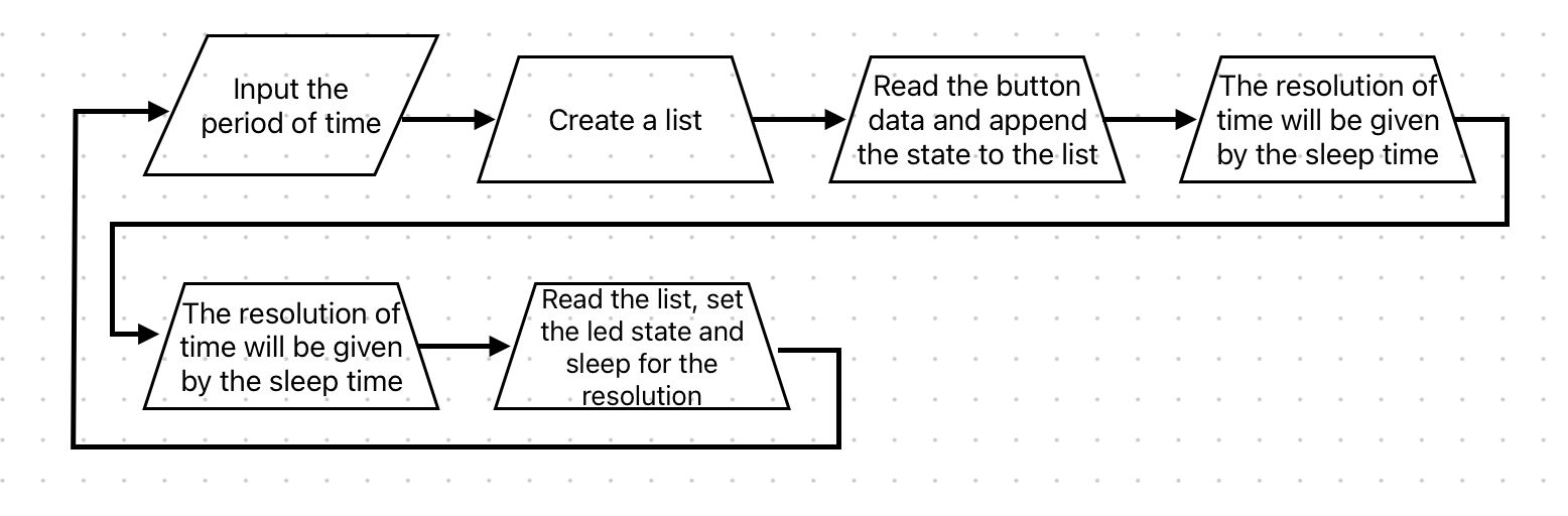
This is what the logic looks like
The program and simulation
What I learned
It seems like I don't know anything about programming, it's not completely different from making it in a code editor, but many things changes, starting with the libraries. and the logic is almost the same but the memory limited space and new libraries makes it a bit harder. And even if I wanted to keep the logic as simple as possible it might not be the better way I learned that arduino is kind of a C+ language and it's quite harder than python. And taking the simulations to the real life is also harder than I thought, I might want to change my final project. I also might want to start knowing where everything this world started to understand this on a better way.