9.Input Devices
This week, I took into account three sensors to understand how proximity sensors function for my final project.🛸🛸
Group Task:
Group taskAnalogic Values (What's beyond 0 and one?)
What is an analog input?
Any component, often some type of sensor, that can provide you with a range of values, not just on and off.
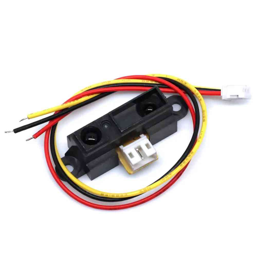
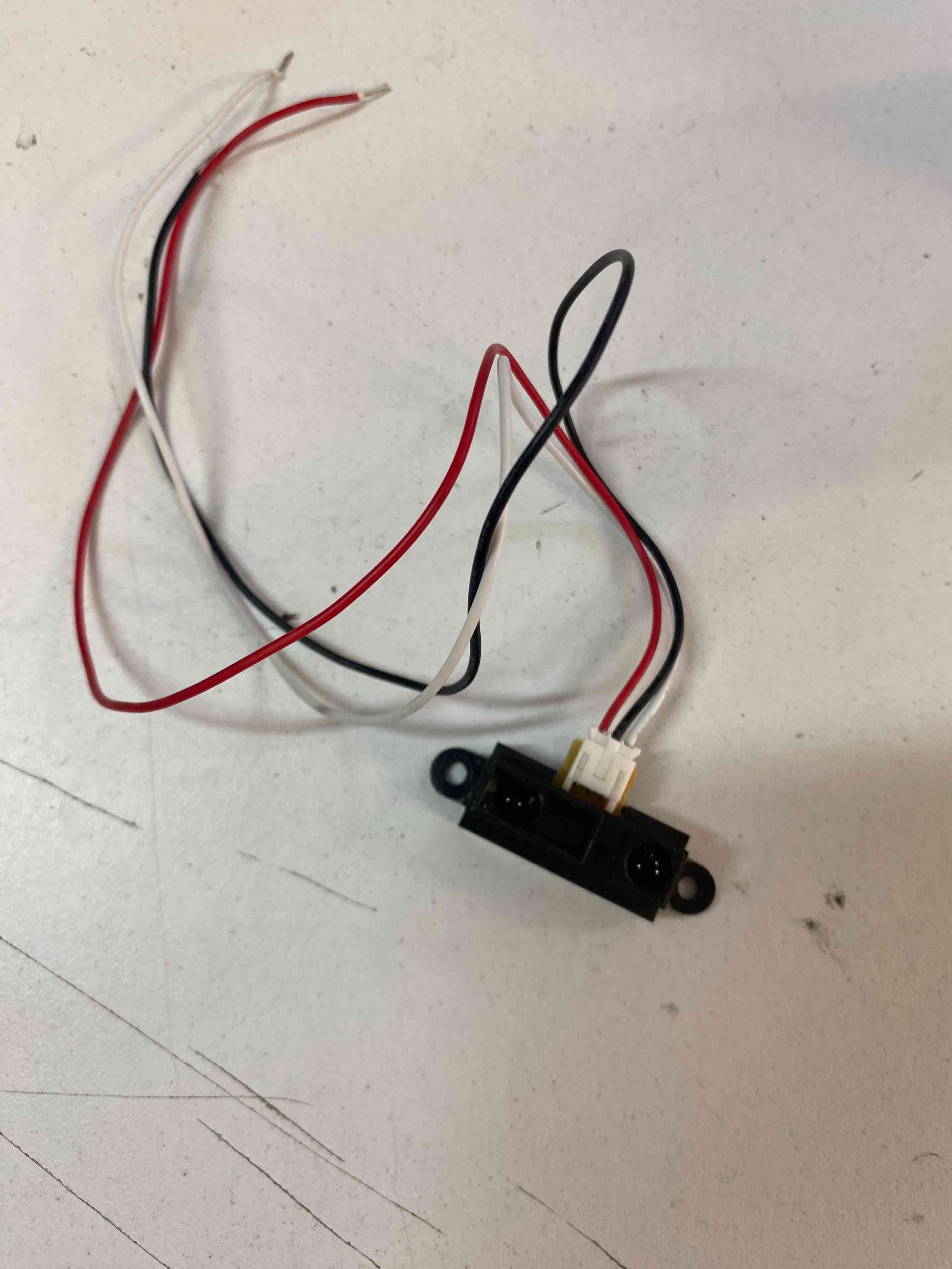
GP2Y0A41SK0F
GP2Y0A41SK0F is a distance measuring sensor unit, composed of an integrated combination of PSD (position sensitive detector), IR-LED (infrared-emitting diode) and (infrared emitting diode) and a signal processing circuit.
To get the formulas in my code I had to analyze the sensor data sheet.
Sensor Data SheetInside this sheet I found important values.
Operating Supply Voltage
| Symbol | Rating | Unit | Remark |
|---|---|---|---|
| Vcc | 4.5 to 5.5 | V | - |
🔹 Electro-optical Characteristics
| Parameter | Symbol | Conditions | MIN. | TYP. | MAX. | Unit |
|---|---|---|---|---|---|---|
| Measuring distance range | ΔL | (Note 1) | 4 | - | 30 | cm |
| Output terminal voltage | Vo | L = 30 cm (Note 1) | 0.25 | 0.4 | 0.55 | V |
| Output voltage difference | ΔVo | Output change at L change (30cm → 4cm) (Note 1) | 1.95 | 2.25 | 2.55 | V |
| Average supply current | Icc | L = 30 cm (Note 1) | - | 12 | 22 | mA |
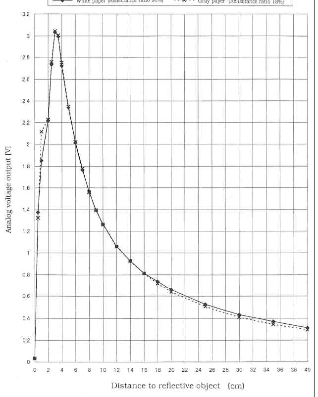
First graph :Shows how the output voltage changes directly with the distance in cm.
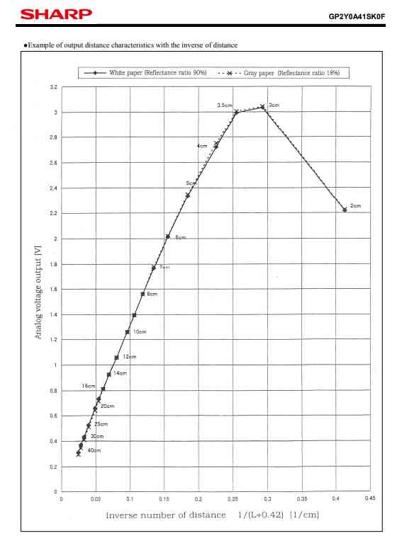
The second graph shows how the output voltage changes as a function of the inverse of the distance, expressed as 1/(L + 0.42) in units of 1/cm.The relationship is reversed because the sensor reacts in reverse (instead of increasing the voltage with distance, it reduces it). At a larger distance, the reflected light is smaller, the number of voltage sends is small. And at a smaller distance, the sensor detects more reflected light and will send a higher voltage.
- Smaller distance - Higher voltage
- Longer distance - Lower voltage
Voltage and Distance Conversion
In this case I relied on the second graph because it is easier and more accurate to convert voltage at a distance.
The XIAO RP2040 has an analog resolution of 12 bits so its values range from 0 to 4095.
Voltage and Distance
Voltage: I am going to take into account the bits that the ADC of the microcontroller has and I am going to pass it to voltage.
To do this I will use a rule of 3 to convert from analog values of 0 to 4095 to 0 to 3.3v.
Formula for Voltage:
The first formula will be:
Actual voltage in volts (VR):
VR = VADC * (3.3 / 4095)
Now I need a formula for the distance.
For this, I will need the value in volts which will be given to me by the sensor.
To do this, I analyzed the second graph and realized that I had to make another rule of three in which I used a value of the real voltage and the distance it gave.
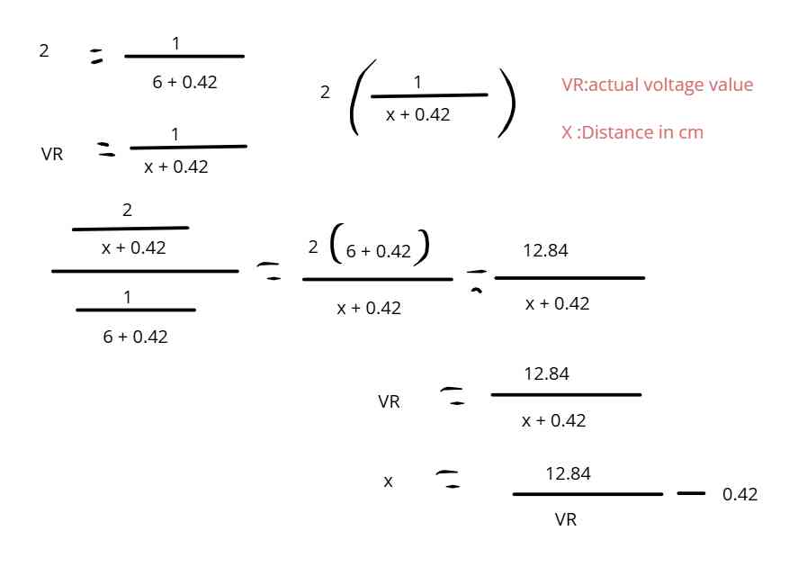
So I obtained this formula that I was going to use for my code:
X = (12.84 / VR) - 0.42
To check, I calculated each voltage and it did match the voltage on the graph.
So I applied these formulas in my code:
			int voltage = SensorValue * (3.3 / 4095);
			int dis = (12.84 / voltage) - 0.42;
programming
Now it's time to program 🛸🛸.
Code
#define pinSensor D2  //Define Sensor Pin
#define pinLeds D0    //Define Leds pin

void setup() {
    Serial.begin(9600);
    pinMode(pinLeds , OUTPUT);  //Define pinLeds as an output
    pinMode(pinSensor , INPUT); //Define pinSensor as an input
}

void loop() {
    delay(500);

    // Read the analog read of pinSensor to calculate the voltage
    float voltaje = analogRead(pinSensor) * (5 / 1023.0);

    // Distance
    float distance = (12.84 / voltaje) - 0.42;

    Serial.print("Distance(cm):");
    Serial.println(distance);

    if (distance < 15 && distance > 4) {
        digitalWrite(pinLeds , HIGH);
    } else {
        digitalWrite(pinLeds , LOW);
    }
}
But when I tried the code, my code didn't give the right distance, so I tried to improve it because I remembered that I only accepted voltages between 4.5V and 5V, but my Xiao only has 3.3V, and that could be the problem. To resolve the problem, I changed the formula in the code: VR = VADC * (5 / 1023.0), as it was originally for a 5V system, and curiously, it gave the correct distance. To check my formula, I tested it on an Arduino, and with this code, it gave the correct distance.The right solution is to use a 5V microcontroller.
The sensor working🛸
Digital Values
I decided to analize 2 sensors : Ultrasonic Sensor and PIR sensor
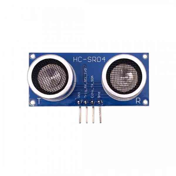
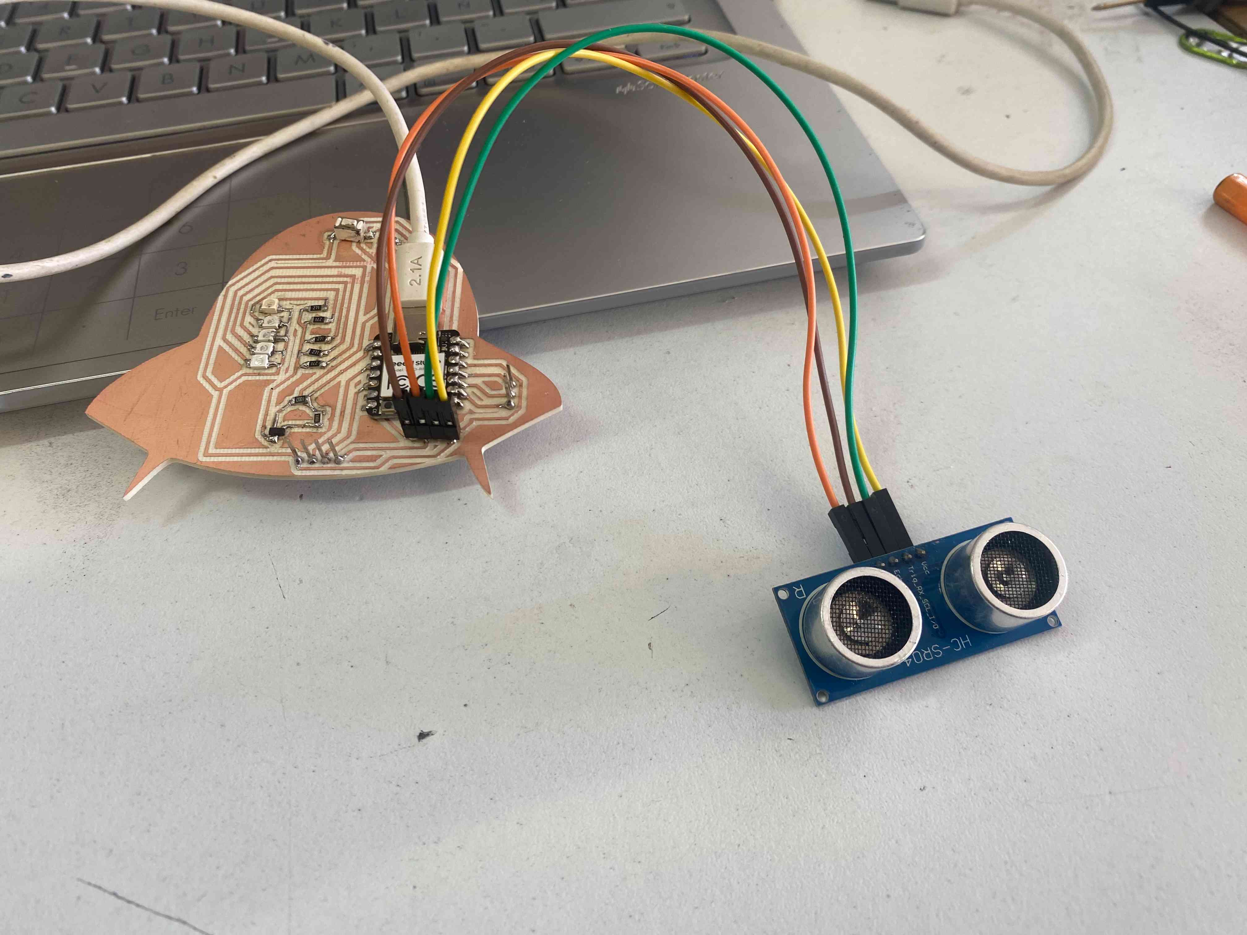
RCWL-9610 Design HC SR 04 Ultrasonic Sensor
An ultrasonic sensor is an instrument that measures the distance to an object using ultrasonic sound waves.
- Supply voltage: 2.8 - 5.5V DC
- Signal voltage: 2.8 - 5.5V (same as supply voltage)
- Detection range: 2-450cm
- Current: < 2mA
- Resolution: 3mm
- Sensor angle: < 15°
- Dimensions: 45 x 20mm
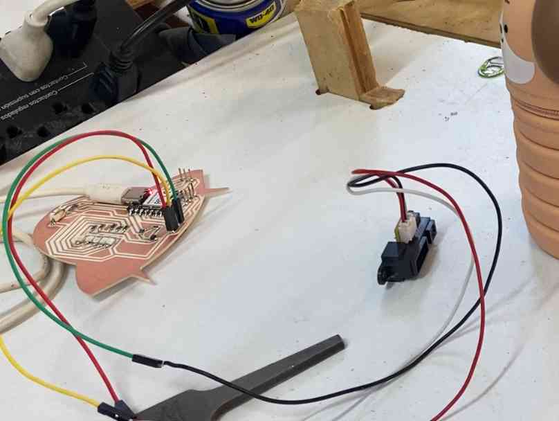
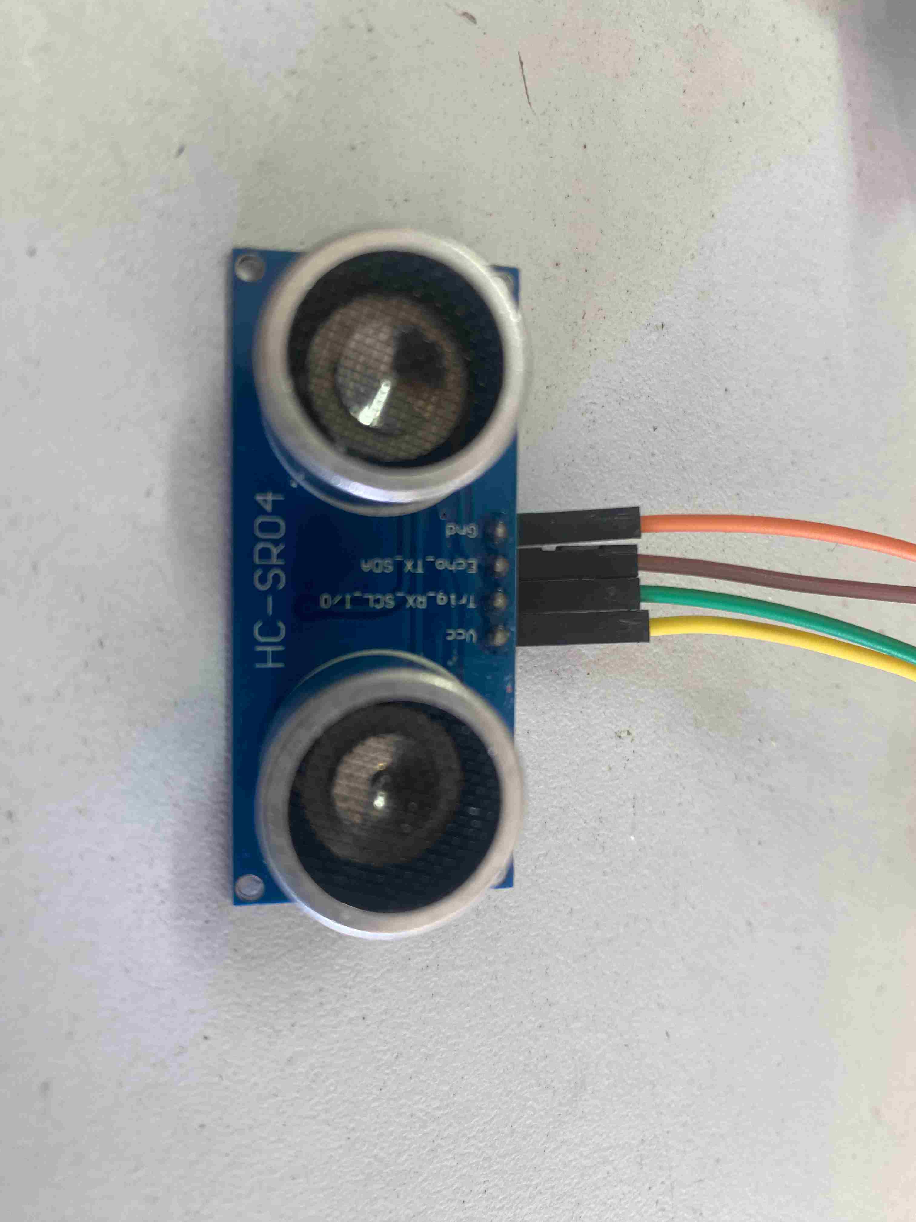
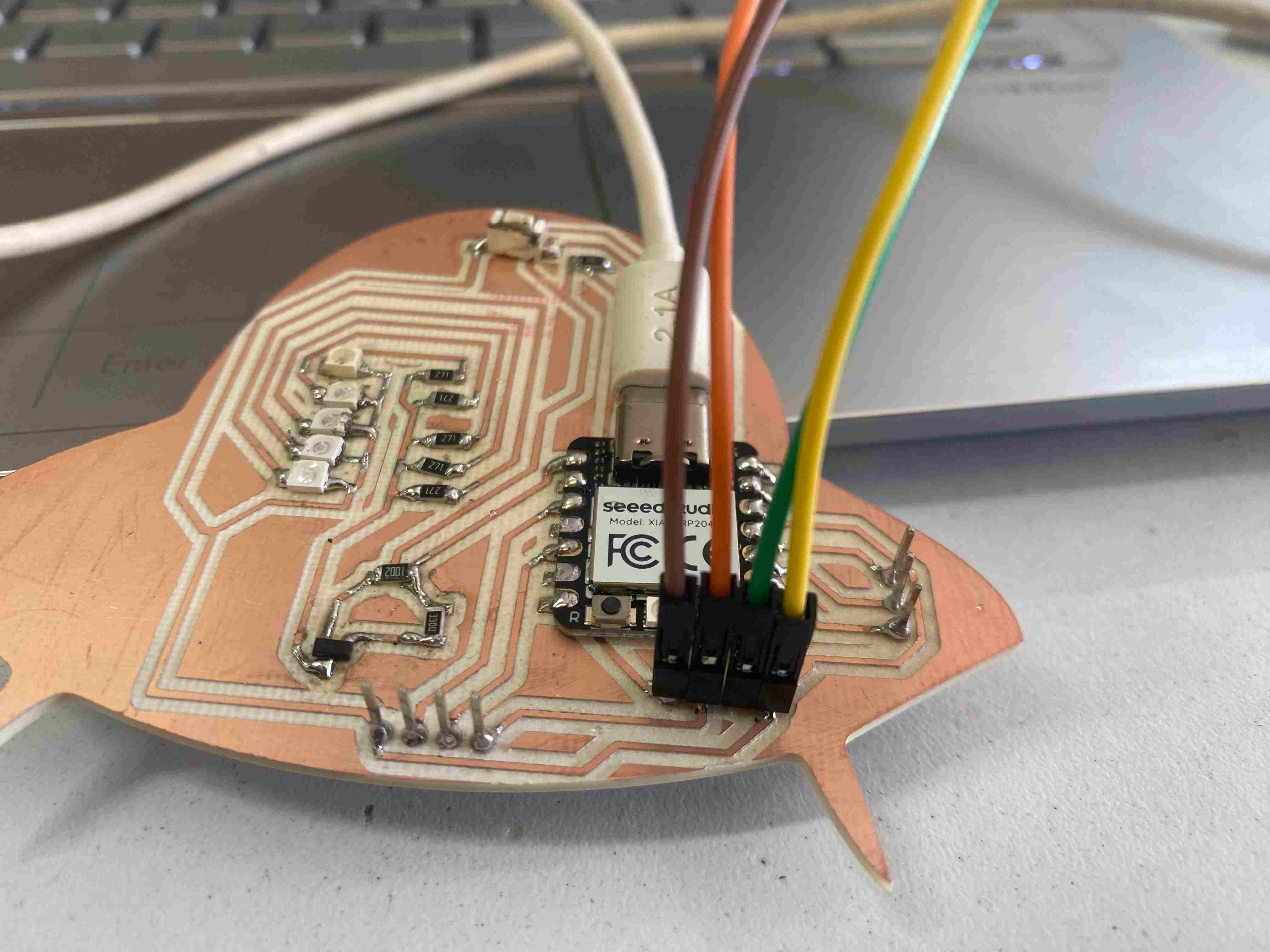
Wiring the Sensor
First, I connected the sensor with the correct pins.
In this case, the sensor has 4 pins:
- Vdc: 5 DC
- Trigger: Input, ultrasonic triggering
- Echo: Output, ultrasound repetition or receiver
- GND: Ground
Formula
In the code, I used the formula:
Distance = speed × time
distance = time * 0.034 / 2;
time=in microseconds0.034=time-to-distance conversion (cm/µs)/ 2=to calculate the one way only
Code
int TRIG = D9;      // pin for the ultrasonic sensor trigger
int ECO = D8;       // pin for the ultrasonic sensor echo
int LED = D0;       // pin that controls the MOSFET for the LED

long time;        // variable to store echo time
int distance;      // variable to store distance

void setup() {
  pinMode(TRIG, OUTPUT);
  pinMode(ECO, INPUT);
  pinMode(LED, OUTPUT);
  Serial.begin(9600);
}

void loop() {
  // Send trigger pulse
  digitalWrite(TRIG, LOW);
  delayMicroseconds(2);
  digitalWrite(TRIG, HIGH);
  delayMicroseconds(10);
  digitalWrite(TRIG, LOW);

  // Read echo time
  time = pulseIn(ECO, HIGH);

  Serial.print("Time: ");
  Serial.println(time);

  // Calculate distance (speed of sound: 340 m/s, divided by 2 and converted to cm)
  distance = time * 0.034 / 2;

  // Show distance on the serial monitor
  Serial.print("Distance: ");
  Serial.print(distance);
  Serial.println(" cm");

  // If the distance is less than 20 cm, turn on the LED
  if (distance < 20) {
    digitalWrite(LED, HIGH);
  } else {
    digitalWrite(LED, LOW);
  }

  delay(500);
}
The sensor working🛸
Pir sensor🛸
I will now analyze the motion sensor(PIR).
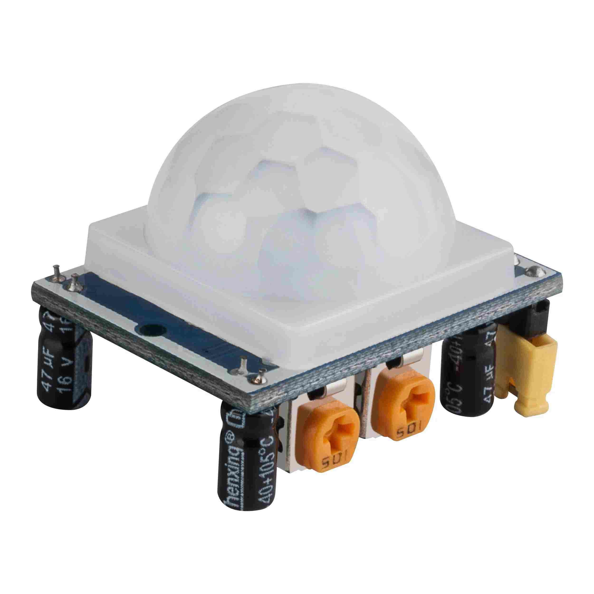
PIR HC-SR501
PIR sensors are optical sensors, they rely on changes in electromagnetic radiation to detect the environment. Specifically, PIR sensors operate in the infrared light range.
Sensor Specifications
- Power supply voltage: 4.5V - 20V DC
- Detection range: 3 to 7 meters (adjustable)
- Detection angle: <100º (cone)
- Delay time: 5-200 seconds (adjustable)
- Working temperature: -20ºC to 80ºC
- The inputs of a PIR sensor (Passive Infrared) are usually the VCC, GND, and OUT pins.5
Code
// Define MOSFET and sensor variables
const int MosfetPin = D0;
const int SensorPin = D4;
int statesensor = 0;

// Define inputs and outputs
void setup() {
  pinMode(SensorPin, INPUT);
  pinMode(MosfetPin, OUTPUT);
  Serial.begin(9600);
}

void loop() {
  statesensor = digitalRead(SensorPin);

  // Condition: if the sensor detects a non-zero value, the LEDs will turn on
  if (statesensor == HIGH) {
    digitalWrite(MosfetPin , HIGH);
  }
  // If the sensor does not detect, the MOSFET will turn off
  else digitalWrite(MosfetPin , LOW);

  delay(300);  // Small delay

  // Print the sensor state (0 or 1)
  Serial.println(statesensor);
}
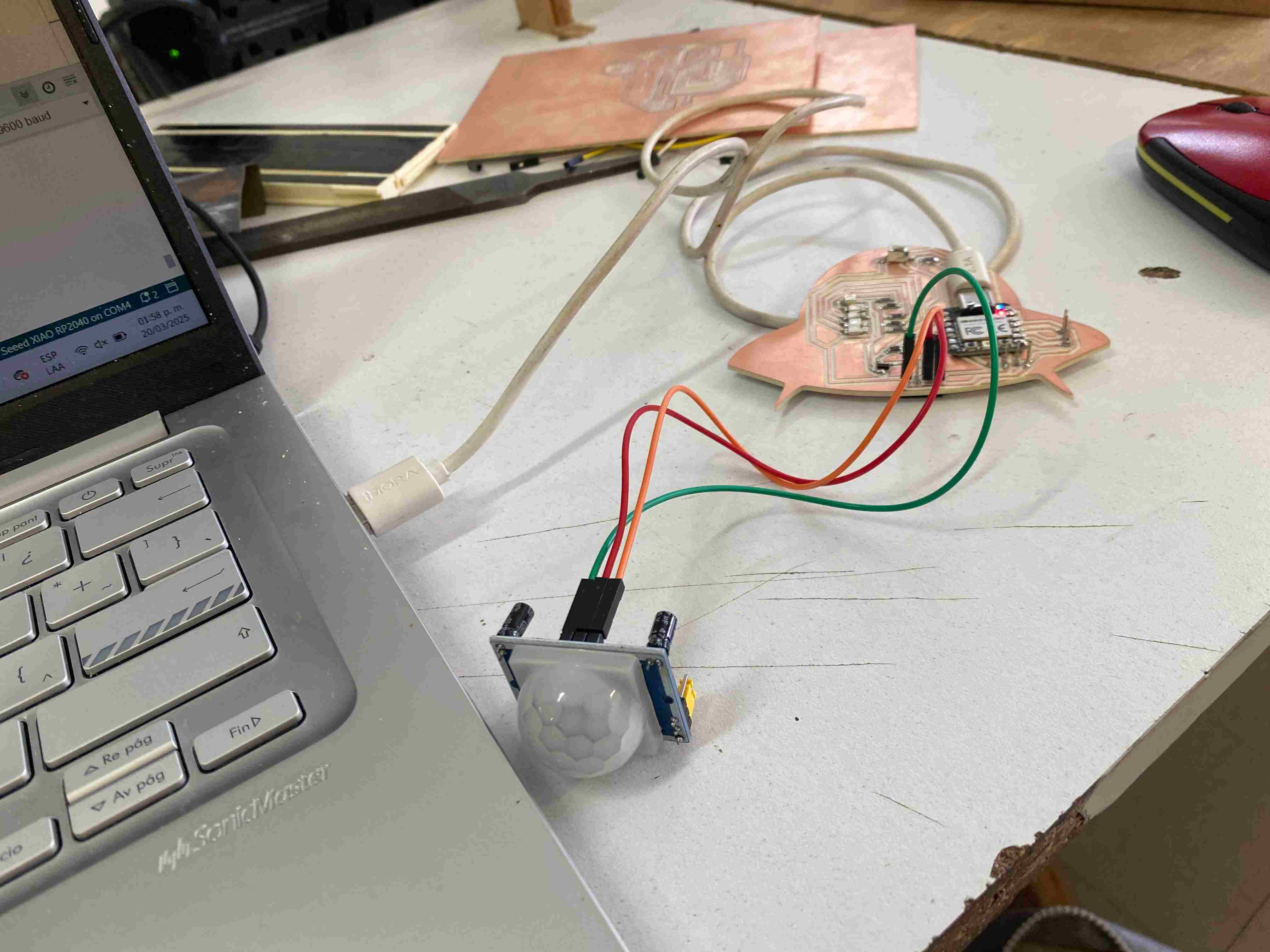
The sensor working🛸
Files
Conclusion🛸🛸
This week was enriching because I learned about analog and digital inputs. It was exciting to see how the sensors could act and provide data.