4.Embedded programming
This week I have started programming.I've been practicing with two programming languages: Python and C++.
Group Task:
Group taskMy first steps in programming
I will start first with Python because I have been told it is more intuitive for beginners. The first thing I did was to understand variables, functions, conditionals and loops. I did some exercises in Python in general to then move on to MicroPython and C++ .
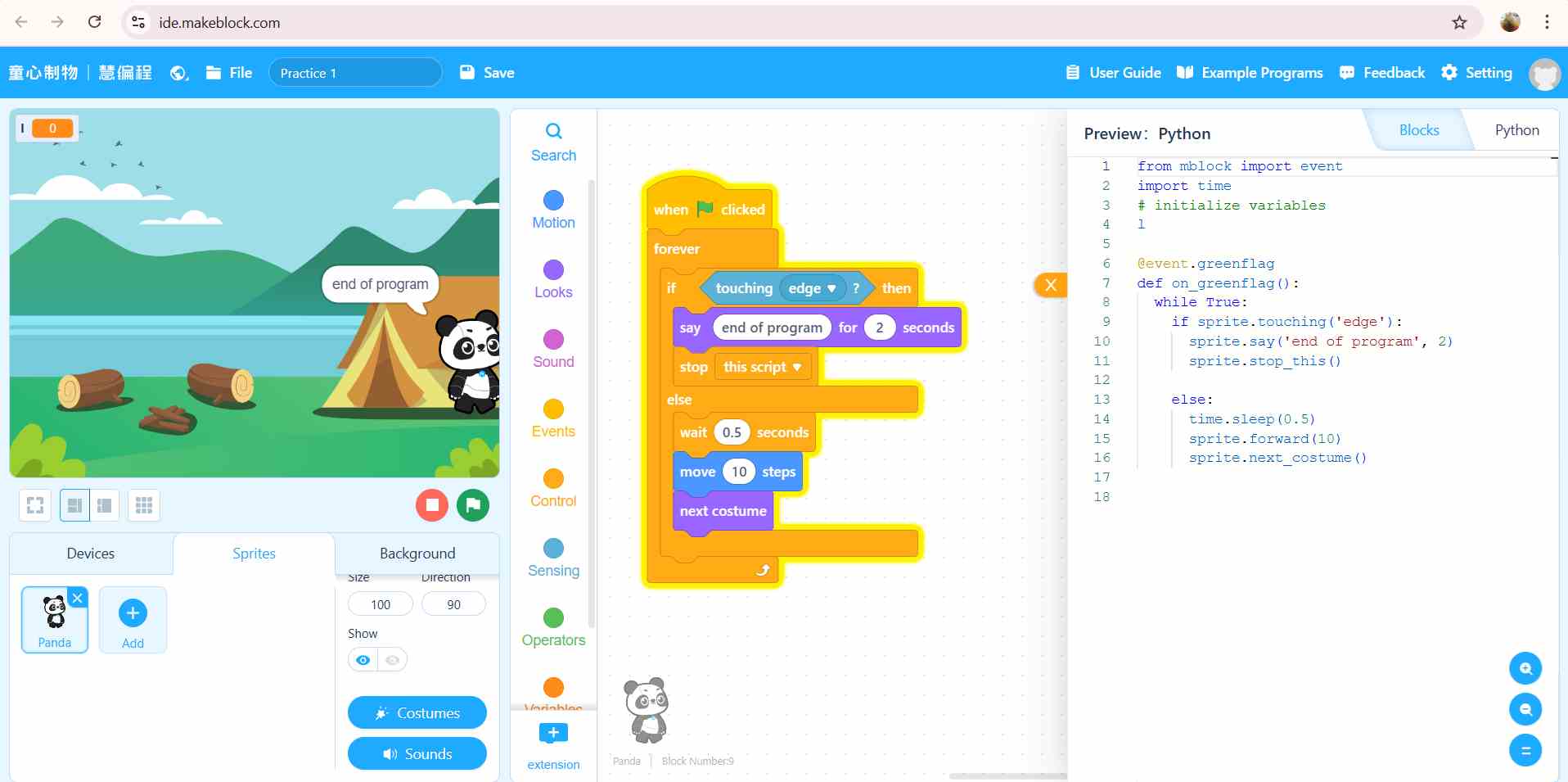
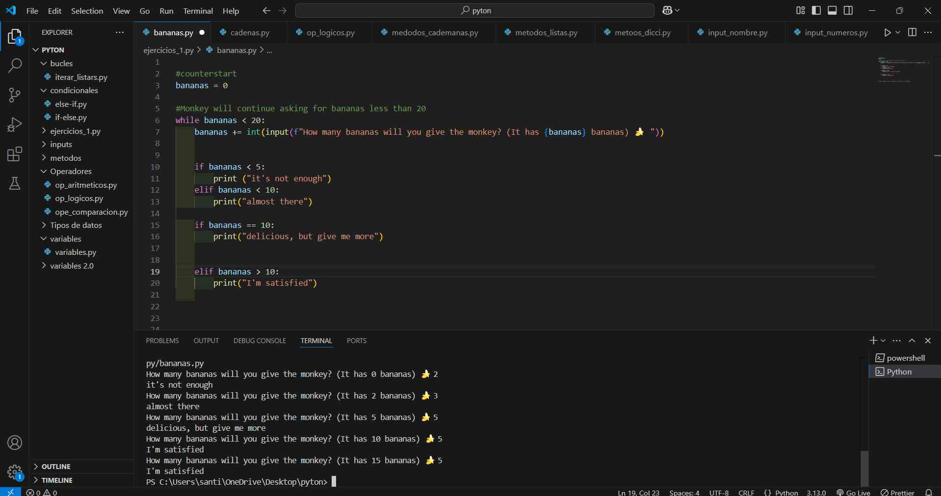
I used two programs. The first was a web page called mBlock to understand the logic through blocks and images.The second was programming in visual studio code.
Study of Circuits and Microcontroller Components
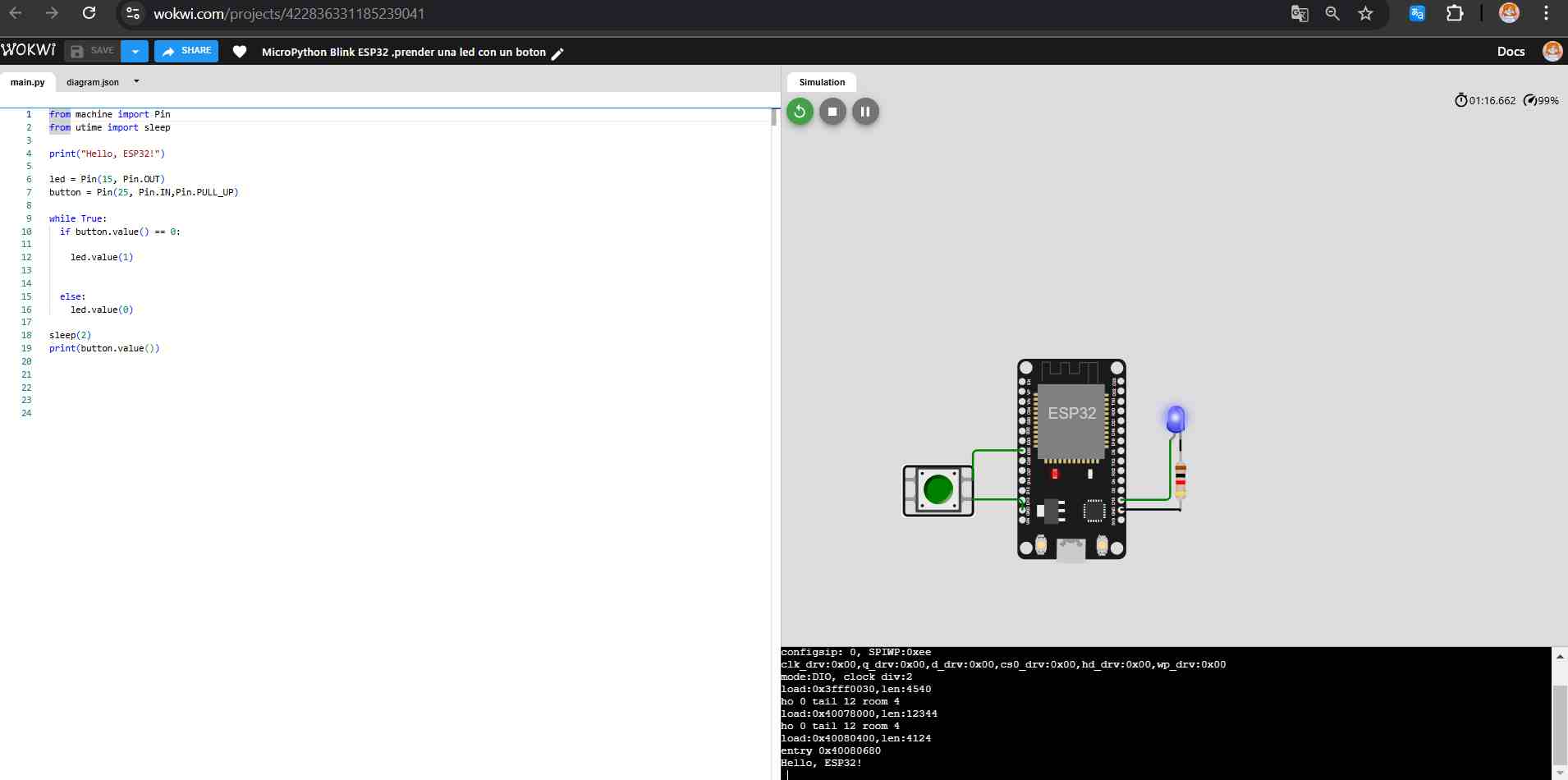
To start programming I used the Wokwi simulator.
Then, I started analizing at some circuits with the microcontroller and the function of each component inside the circuit.
To understand these things, I started with MicroPython. Here I had to choose which microcontroller to use for my simulation.
Definition of microcontroller:
A microcontroller unit (MCU) is essentially a small computer on a single chip. It is designed to handle specific tasks within an embedded system without the need for a complex operating system.
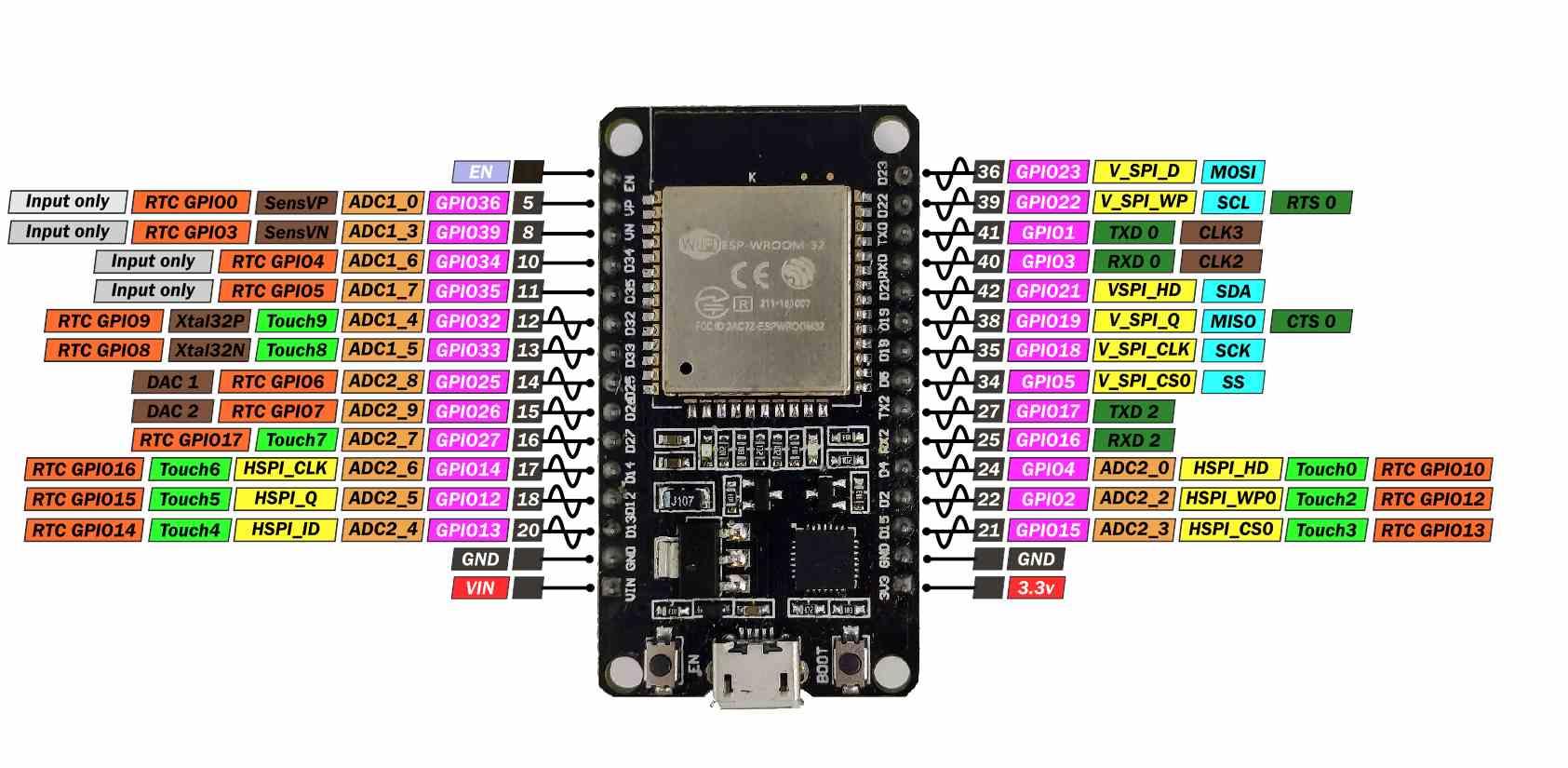
I explored some microcontrollers and found the ESP32 microcontroller for its features.
ESP32 DevKit V4 Hardware Specifications
- Microcontroller: ESP32-WROOM-32D with dual-core processor at 240 MHz.
- Memory: 4 MB flash memory and 520 KB SRAM.
- Wireless Connectivity: Wi-Fi 802.11 b/g/n/e/i, Bluetooth v4.2 BR/EDR and BLE.
- I/O Interfaces: 36 GPIO pins (including analog input and PWM pins), UART, SPI, I2C, I2S, ADC, and DAC.
- Power Supply: 5V input via micro-USB connector or 3.3V via GPIO pins.
- LEDs: Power indicator LED.
- Antenna: Integrated PCB antenna.
- MicroSD Card Slot: Supports cards up to 4 GB.
- Dimensions: 53 mm x 28.5 mm x 14.2 mm.
- programmable in: C++, MicroPython, CircuitPython, ESP-IDF, JavaScript (Espruino), Lua (NodeMCU), Rust, and TinyGo.
To understand the pins, I imagined that the ESP32 was a robot and the pins were the arms of the robot. Each leg has a different function. For example: GPIO pins are like normal legs; they can activate LEDs and receive information. GND is the return path; it is called “ground”. ADC helps with things like controlling light brightness and is useful for light and temperature sensors. DAC can apply force to a variable, for example, to increase brightness or volume slowly.2 And so on with the other pins.
MicroPython
Now, for the code, I started with MicroPython.
First, I began with basic tasks, like turning on a light with a button. a Then, I used a PIR sensor for my final project and turned on the lights with this sensor.
| Concept | Description |
|---|---|
| Variables | Store data (integers, floats, strings) for use in the program. |
| Pins | Digital or analog input/output pins used for hardware interaction. |
| Functions | Blocks of code that perform a specific task, defined using def. |
| Control Structures | Control the program flow, such as if, for, while. |
| Libraries | Pre-written code to interact with hardware, like machine for GPIO. |
| UART | Used for serial communication between devices. |
| Timers | Used to run functions periodically with the Timer class. |
| Interrupts | Allows response to specific events (e.g., button presses) without polling. |
| I2C and SPI | Protocols for communication with sensors and devices (machine.I2C or machine.SPI). |
| Exceptions | Handles errors using try, except blocks. |
(This table was created by ChatGPT). Promt: “Give me a short table of MicroPython concepts”.
- First, I import the library to control the pins with these functions: from machine import Pin: Then, I configure my pins with their locations, like LEDs on the microcontroller.
- I configured everything as output pins and also configured the sensor: sensor = Pin(26, [Pin.IN])
- Then, I added a condition that says that as long as the sensor detects motion (value 1), the LEDs will have a value of 1, and the console will print the sentence “A motion was detected”. Otherwise, if the sensor does not detect motion (value 0), the LEDs will have a value of 0.
- I added the function time.sleep(), which pauses the program to allow the LEDs to turn on.
Code in Micropython
from machine import Pin

sensor = Pin(26, Pin.IN)

#location of the LEDs on the microcontroller
led1 = Pin(15, Pin.OUT)
led2 = Pin(2, Pin.OUT)
led3 = Pin(4, Pin.OUT)

print("If it detects movement, the LEDs will turn on")
#Location of the sensor
sensor = Pin(26, Pin.IN)


while True:
  if sensor.value() == 1:

    led1.value(1)
    led2.value(1)
    led3.value(1)
    print("a movement was detected")

  else:
    led1.value(0)
    led2.value(0)
    led3.value(0)
time.sleep(0.5)
This is my video in Wokwi with microphyton with MQTT connection, but later I will explain how I did it.
Programming in C++ (Arduino)
Next, I tried the same thing in C++.
- First I start defining my pins.
- Then I set void setup() is used to do the initialization tasks. Serial.begin()is to start the serial communication between the microcontroller and a computer. Serial.println is to print a message to the "Serial Monitor".
- Then configure the sensor pin as input and the light pins as output.
- I used the void loop() function that keeps the program running continuously. To set the conditional, I put if the pir status is high, the light is also high and they turn on but if the pir status is low, the light is also low.
- To print the messages I use the Serial.println() function.
First, here is a table with the most important concepts in Arduino C++:
| Concept | Description |
|---|---|
| Variables | Store data (integers, floats, strings) for use in the program. |
| Pins | Digital or analog input/output pins on the Arduino board. |
| Functions | Blocks of code that perform a specific task, such as setup() and loop(). |
| Control Structures | Control the program flow, such as if, for, while. |
| Libraries | Pre-written code that adds functionality, such as controlling sensors or motors. |
| Serial Communication | Allows sending and receiving data between Arduino and a computer using Serial.begin(). |
| Analog vs Digital | Analog signals (continuous values) and digital signals (high/low). |
| I/O Functions | Interacts with pins, such as pinMode(), digitalWrite(), digitalRead(). |
| Delays | Pause the program execution, e.g., delay(1000) for 1 second. |
(This table was created by ChatGPT). Promt: “Give me a short table of Arduino C++ concepts”.
I began with basic tasks, like turning on lights following a sequence.
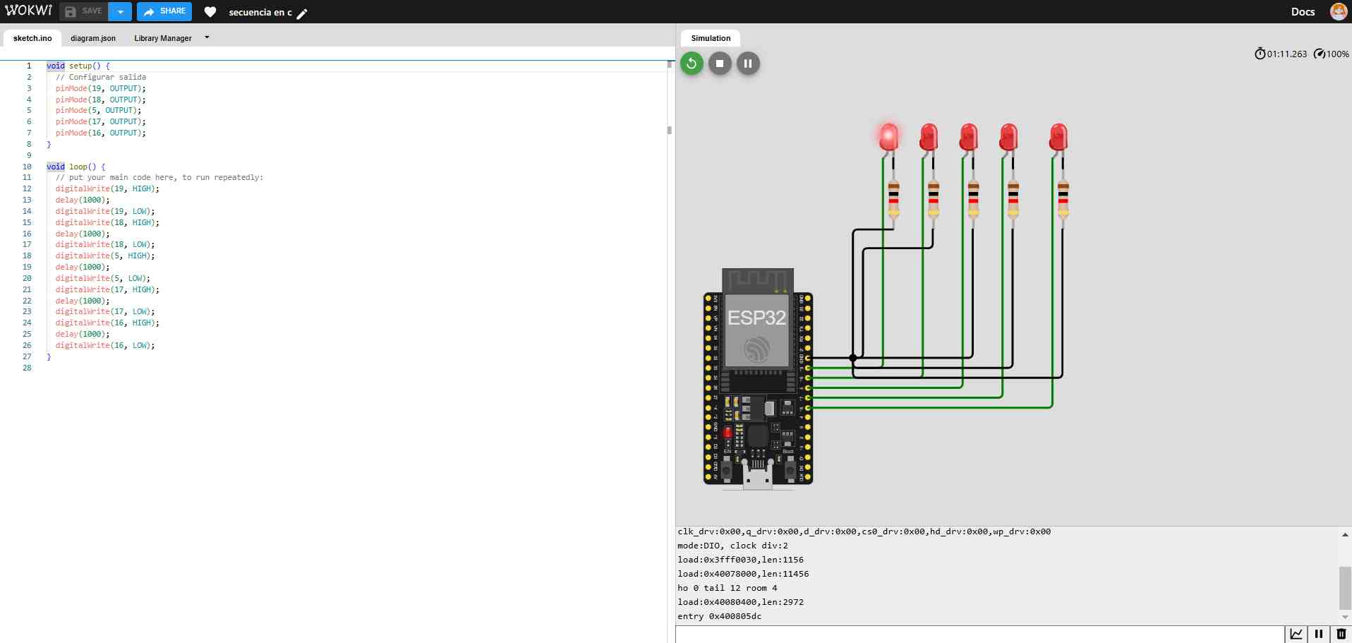
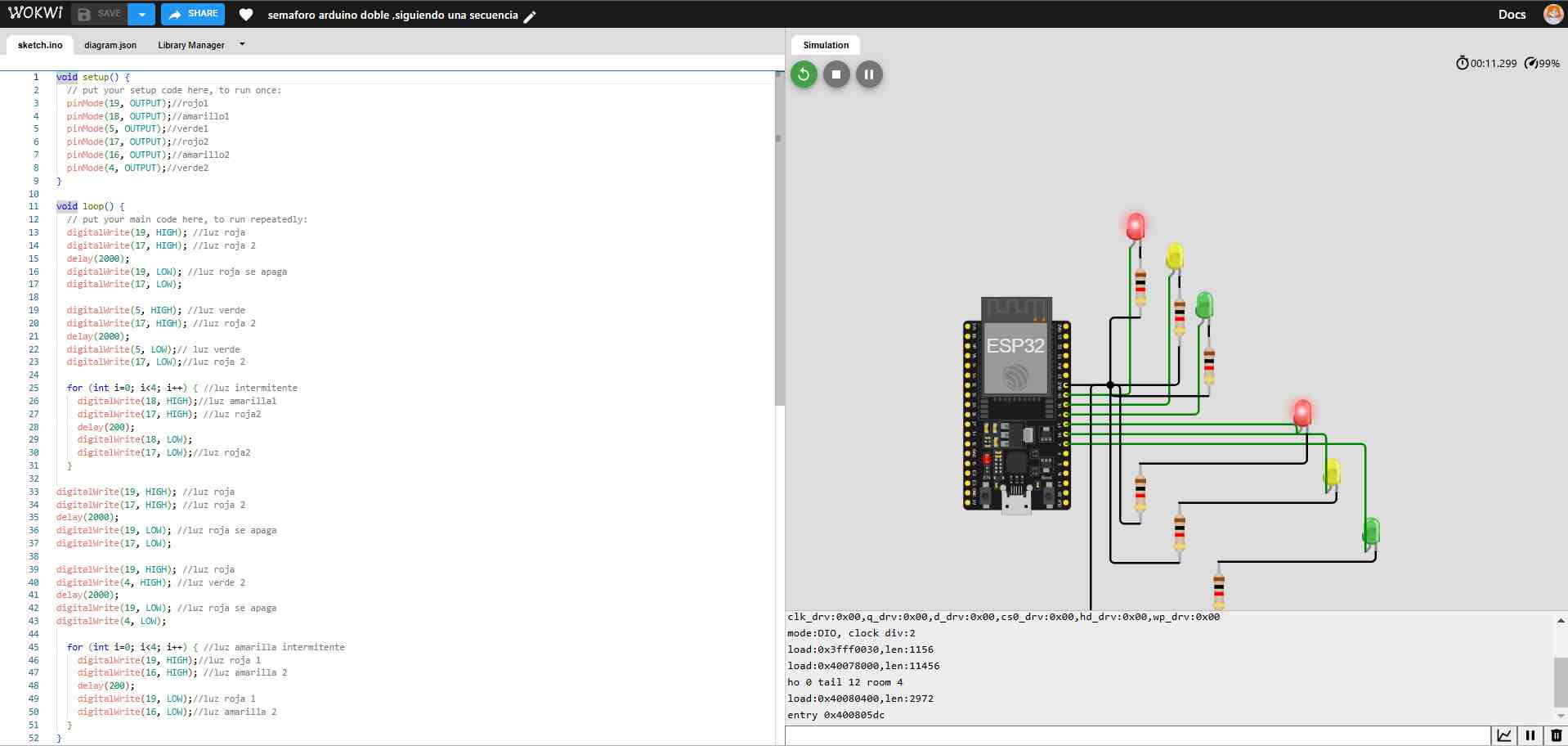
Code in Arduino C++
#define PIR_PIN 12
#define Led1 18
#define Led2 5
#define Led3 17


void setup() {
  // put your setup code here, to run once:
  Serial.begin(115200);
  Serial.println("Hello, ESP32!");
  pinMode(PIR_PIN, INPUT);
  pinMode(Led1, OUTPUT);
  pinMode(Led2, OUTPUT);
  pinMode(Led3, OUTPUT);


}

void loop() {
  // put your main code here, to run repeatedly:
  int estadoPIR = digitalRead(PIR_PIN);
  delay(10);

  if (estadoPIR == HIGH) {  // if there are movements
        digitalWrite(Led1, HIGH);
        digitalWrite(Led2, HIGH);
        digitalWrite(Led3, HIGH);
        Serial.println("Motion detected! LEDs on.");
  } else {                 // if there aren't movements
        digitalWrite(Led1, LOW);
        digitalWrite(Led2, LOW);
        digitalWrite(Led3, LOW);
        Serial.println("No movement. LEDs off.");
  }

}
Comunication with internet
To create a communication, I decided to use the wireless connection, in this case the Internet. I used MQTT to send messages with the sensor and saw an example of a temperature sensor.
Example extracted from Wokwi
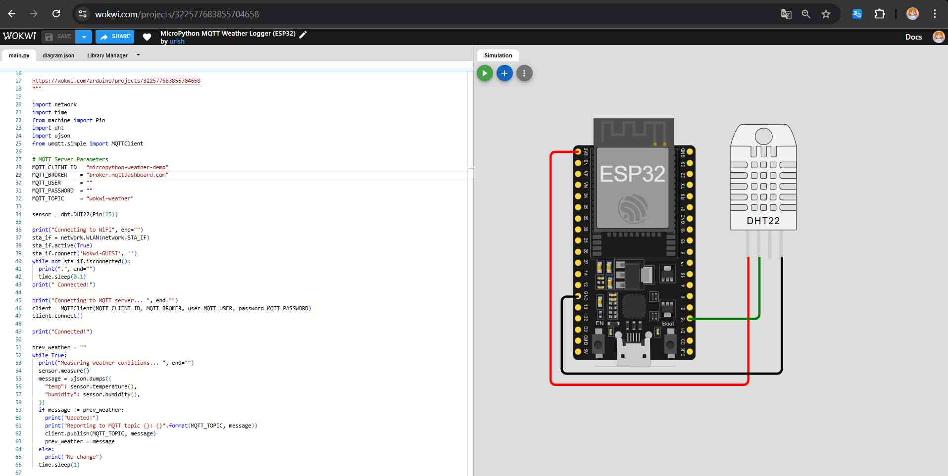
I tried to do the same with my PIR sensor.
- First, I had to understand some basic concepts:
- What is MQTT? MQTT (Message Queuing Telemetry Transport) is a messaging protocol that allows devices to communicate over bandwidth-limited networks. It is a key part of the Internet of Things (IoT) and is used in many applications, including smart devices and industrial automation.
- from umqtt.simple import MQTTClient This imports the MQTT client library to connect to an MQTT broker.
- MQTT_CLIENT_ID: Sets a unique identifier for the MQTT client.
- MQTT_BROKER: Defines the address of the MQTT server to connect to.
- MQTT_USER: Defines the user name for the MQTT connection (empty if not required).
- MQTT_PASSWORD: Defines the password for the MQTT connection (empty if not required).
- MQTT_TOPIC: Defines the topic for sending or receiving messages.
- To connect to the internet in Python, I have to set the pin of the sensor that MQTT is going to read.
- Next, I print the Internet connection messages, and it is important to use end=“” to print a message without going to the next line.
- network.WLAN(network.STA_IF): This prepares the chip to use Wi-Fi in client mode (STA_IF).
- sta_if.active(True): This activates the Wi-Fi interface to start scanning for networks.
- Then, I set the Wi-Fi network in this case to the simulator:
- sta_if.connect('Wokwi-GUEST', '').
- When connected, the print statement sends “connected” to the console.
.png)
These lines set the connection parameters for the MQTT client:
MQTT conection program with Pir sensor
import network
import time
from machine import Pin
from umqtt.simple import MQTTClient

# MQTT Server Parameters
MQTT_CLIENT_ID = "micropython-movment-demo"
MQTT_BROKER    = "broker.mqttdashboard.com"
MQTT_USER      = ""
MQTT_PASSWORD  = ""
MQTT_TOPIC     = "wokwi-movement"

sensor = Pin(26, Pin.IN)
print("Connecting to WiFi", end="")
sta_if = network.WLAN(network.STA_IF)
sta_if.active(True)
sta_if.connect('Wokwi-GUEST', '')
while not sta_if.isconnected():
  print(".", end="")
  time.sleep(0.1)
print(" Connected!")

print("Connecting to MQTT server... ", end="")
client = MQTTClient(MQTT_CLIENT_ID, MQTT_BROKER, user=MQTT_USER, password=MQTT_PASSWORD)
client.connect()

print("Connected!")
#location of the LEDs on the microcontroller
led1 = Pin(15, Pin.OUT)
led2 = Pin(2, Pin.OUT)
led3 = Pin(4, Pin.OUT)

print("If it detects movement, the LEDs will turn on")
#Location of the sensor
sensor = Pin(26, Pin.IN)


while True:
  if sensor.value() == 1:

    led1.value(1)
    led2.value(1)
    led3.value(1)
    print("a movement was detected")
    client.publish(MQTT_TOPIC, "Detected movement")

  else:
    led1.value(0)
    led2.value(0)
    led3.value(0)
time.sleep(0.5)
Conclusion
This week has been a challenge because I had to research how each function of each component works in order to program, and then I had to learn how to program in two languages I didn't know. Although I have only programmed basic things, Now i understand how to do it. Between the two languages: MicroPython and Arduino C++, I prefer MicroPython because it is very intuitive, but I would also like to continue with Arduino C++. In the case of this, although it has been a bit more difficult because its syntax is more structured. I would like to continue learning how to optimize code in Arduino and better understand the handling of libraries and control structures. I liked this week because I learned things I didn't understand before and I think I'm progressing well.