17. Wildcard Week
For Wildcard Week, I decided to create a compact smart plant monitoring device that combines
embedded electronics,environmental sensing, packaging design, and digital fabrication techniques.
The system will use a Seeed Studio XIAO RP2040 microcontroller together with a Capacitive Analog
Soil Moisture Sensor to monitor soil moisture levels and visually communicate plant conditions
using three LED indicators.
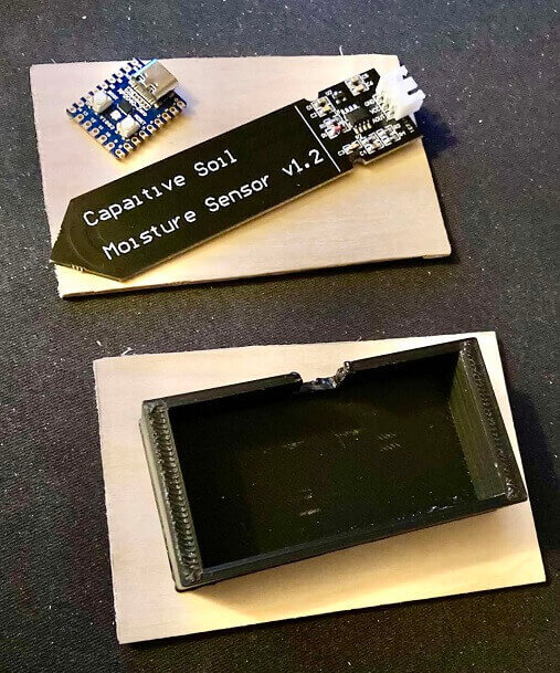
An older unused enclosure from a previous project will be repurposed as the internal electronics
and wiring compartment for this build. The enclosure was originally 3D printed using PLA filament
and will now function as the structural center section of the device. To improve the overall
appearance and create a more finished product aesthetic, the outer visible housing will be
redesigned using thin wooden panels mounted to the front and back of the black PLA enclosure.
The wooden outer panels will be fabricated from 1/16-inch thick wood pieces measuring approximately
3 3/4 inches by 2 3/8 inches. Since I was working from home and not inside a lab or woodshop environment,
I used scissors to cut the wooden pieces by hand. Fortunately, because the wood was only 1/16-inch thick,
it was soft and flexible enough to cut relatively easily without requiring larger woodworking equipment.
This became part of the fabrication process and demonstrated how lightweight materials could still be
shaped and customized using simple household tools.
One wooden panel will serve as the front face of the device and will contain three LED mounting
holes representing different moisture conditions:
* green LED = healthy moisture level
* blue LED = soil becoming dry
* red LED = dry soil requiring water
The front wooden panel will also include a decorative wood-burned design, possibly featuring a plant
leaf or water droplet graphic to reinforce the environmental monitoring theme of the project.
The capacitive soil moisture sensor will be mounted internally using hot glue and attached to the
non-visible inner wooden support panel facing the internal electronics compartment. This approach
helps keep the external appearance cleaner while also securely positioning the sensor and wiring
inside the enclosure.
The moisture sensor will continuously collect analog soil readings and send the data to the XIAO
RP2040. Based on programmed threshold values, the microcontroller will activate the appropriate
LED indicator to visually display the current soil condition.
This project combines additive fabrication, subtractive fabrication, embedded programming, sensor
interfacing, electronics integration, packaging design, enclosure refinement, and material reuse
into a compact smart plant monitoring device for Wildcard Week.
2D Sketch & a few 3D Renders
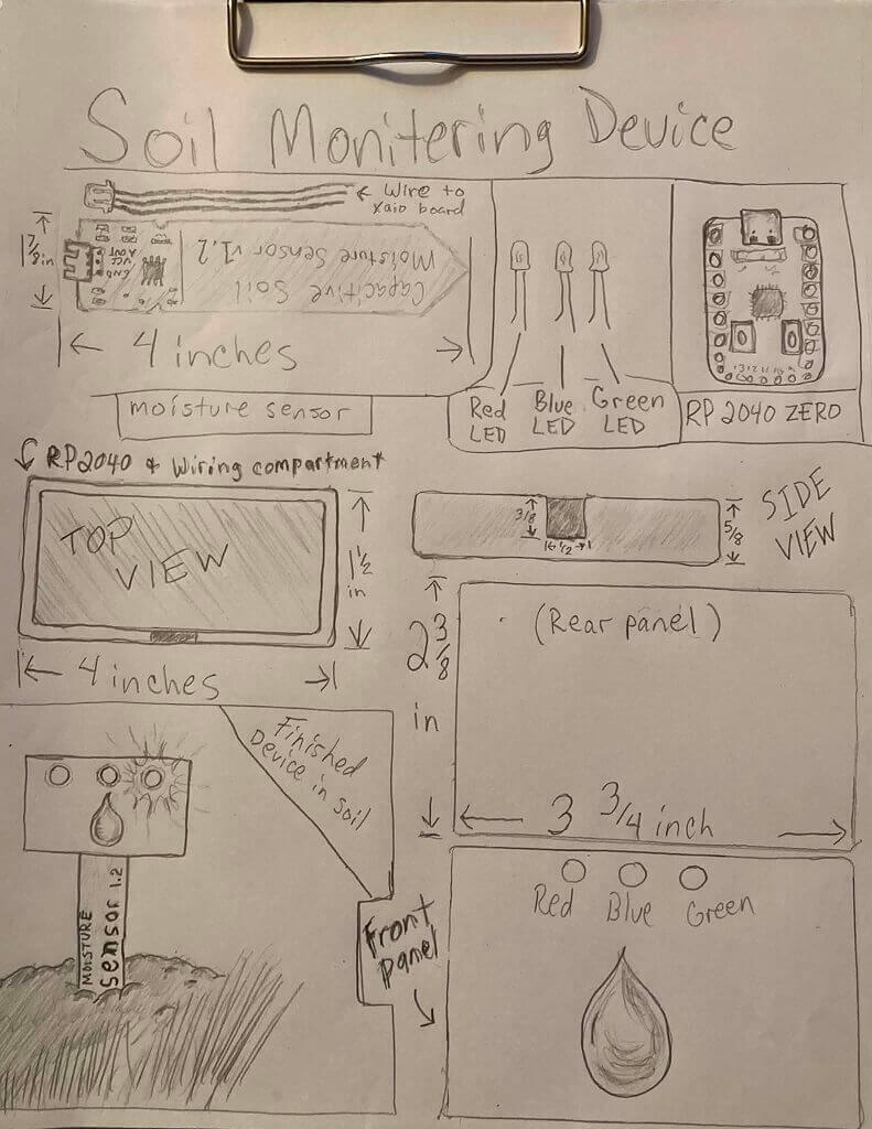
Ideas on paper
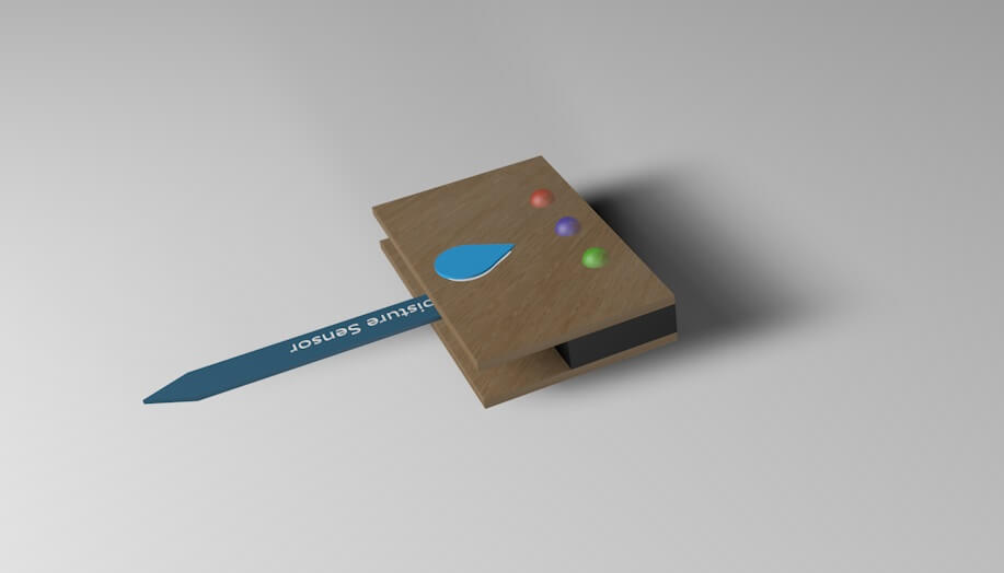
1st render of moisture sensor device
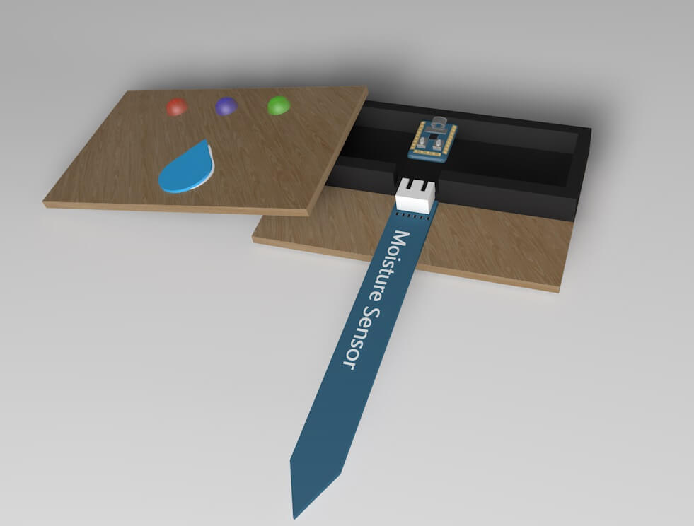
Front cover removed
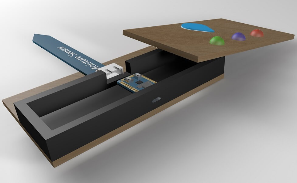
Another angle
A few of the tools I will be using
Checklist
- - Demonstrate workflows used in the chosen process
- - Select and apply suitable processes (and materials) to do your assignment
- - Document the workflows and processes used
- - explain how your process is not used in other assignments
- - describe problems you encountered (if any) and how you fixed them
- - include design files and source code
- - Included hero shot(s)
Select and apply suitable processes (and materials) to do your assignment
Several fabrication methods and materials were selected based on simplicity,
availability, compactness, and overall project goals.
- PLA 3D printed enclosure
- 1/16-inch wood panels
- hot glue
- jumper wires
- LEDs
- resistors
- USB power cable
Electronics Used
- Seeed Studio XIAO RP2040
- Capacitive Analog Soil Moisture Sensor
The PLA enclosure was reused to reduce waste while also serving as a lightweight internal
electronics compartment. Thin wooden panels were selected because they were easy to shape,
lightweight, and visually improved the overall appearance of the device. Hot glue was used
for quick internal mounting and packaging during assembly.
Demonstrate workflows used in the chosen process:
For this Wildcard Week assignment, I combined multiple fabrication and embedded systems
workflows into a single compact smart plant monitoring device. The project workflow included
digital planning, additive fabrication reuse, subtractive fabrication, embedded electronics
integration, packaging design, and microcontroller programming.
The project workflow began with concept sketches and layout planning to determine enclosure
dimensions, LED placement, sensor positioning, and internal wiring organization. Existing 3D
printed components from a previous unfinished project were repurposed as the internal electronics
housing. Additional wooden front and rear panels were then fabricated and customized to improve
the visual appearance and packaging quality of the device.
After enclosure planning and fabrication, the electronics integration workflow included wiring the
capacitive soil moisture sensor, LEDs, resistors, and XIAO RP2040 microcontroller. Embedded programming
was then used to interpret analog soil moisture values and visually display soil conditions using
color-coded LED indicators.
Document the Workflows and Processes Used
Design Workflow- hand sketches
- 3D concept renders
- dimension planning
- LED placement planning
Fabrication Workflow
- cutting wood panels
- drilling LED holes
- mounting sensor
- assembling enclosure
Electronics Workflow
- wiring LEDs
- wiring sensor
- connecting XIAO RP2040
- testing analog values
Programming Workflow
- reading analog moisture values
- creating threshold ranges
- controlling LEDs
- troubleshooting sensor readings
Packaging Workflow
- organizing internal wiring
- mounting electronics
- enclosing components
- improving visual appearance
Explain How This Process Was Not Used in Other Assignments
This workflow differed from my previous assignments because it focused more heavily on packagingdesign, enclosure refinement, material reuse, and hybrid fabrication methods rather than only electronics
functionality. Previous assignments primarily focused on sensor operation, microcontroller programming,
and basic prototyping.
For this assignment, I combined additive fabrication reuse with subtractive fabrication by integrating
an older PLA 3D printed enclosure together with newly fabricated wooden exterior panels. The project
also placed greater emphasis on creating a compact finished product aesthetic instead of a temporary
prototype or breadboard-based system.
Problems Encountered
I didn't have any cutting tools for the original wood pieces that I were originally going to use.
That wood was 1/8 thick, but the wood that I ended up going with is 1/16 thick. So as a result I
Used a pair of heavy duty scissors to cut the very thin 1/16 wood pieces to the desired spec.
The .stl file for download
Moisture sensor deviceI designed the 3D file in Cinema 4D. I thought about using
Fusion 360 or Tinkercad but I have beenusing Cinema 4D
for so long, alot of things are easier to generate in less time.
Setting up and testing code in Arduino Ide
When I first connected moisture sensor, I had arduino ide seriol moniter running.
When the sensor was not touching anything and was completely dry, I got a return value
that fluctuated between 385-450. So I already had a starting base value pool that was in
the mid lower 400's and even as low as 385.
Next I fully submerged the sensor in a glass of water and the return values fluctuated from
190 - 215. So now that I had my wet and dry values. So I tested and made sure that the
sensor could accurately read values. The next thing to do is solder a few single led's.
I use 220 ohm resisters with 3/5mm led's.
After the led's are made, I will connect them to the rp 2040 xaio to make sure they are
functioning properly and upon doing so. Code them so that they react the way the program
commands them to. Wet = green led, Dry = red led. Transition gets no led
Transition is the time in between getting the correct values not with a certain threshold.
Video of moisture sensor test
I wrapped a damp paper towel over the sensor, to start the video. The status
returned a "damp" value. These are tests I ran in arduino ide serial monitor.
To test for wet sample I just filled a small glass jar with water. It worked
just fine.
Let the testing begin...
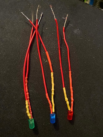
Led's ready to be tested
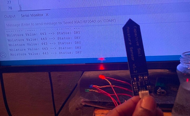
Sensor is dry, so red led is illuminated
Are we missing an LED.....no
So as you may have noticed. The original concept had 3 leds and the final product only has 2.
Well, a last minute decision was made to test initial wetness only. I have ideas down the line
to add on to this device and extend the code to allow the device to do more. But at the moment
there are larger project that I am diving into. As arsult I decided to go with a wet/dry test only
for this project. I thought about other features, but those ideas can be implemented at a later date.
I'm happy to get this project completed.
Pronounced as Soil-T....a play on words like loyalty. A loyal moisture tester.
Hero Shot
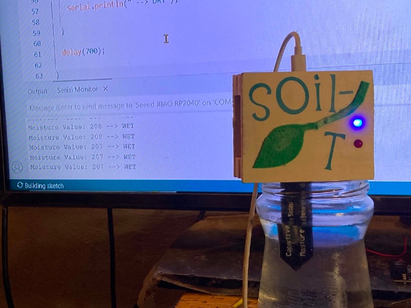
It works !!!!!!!!!!!
Video of the device functioning properly