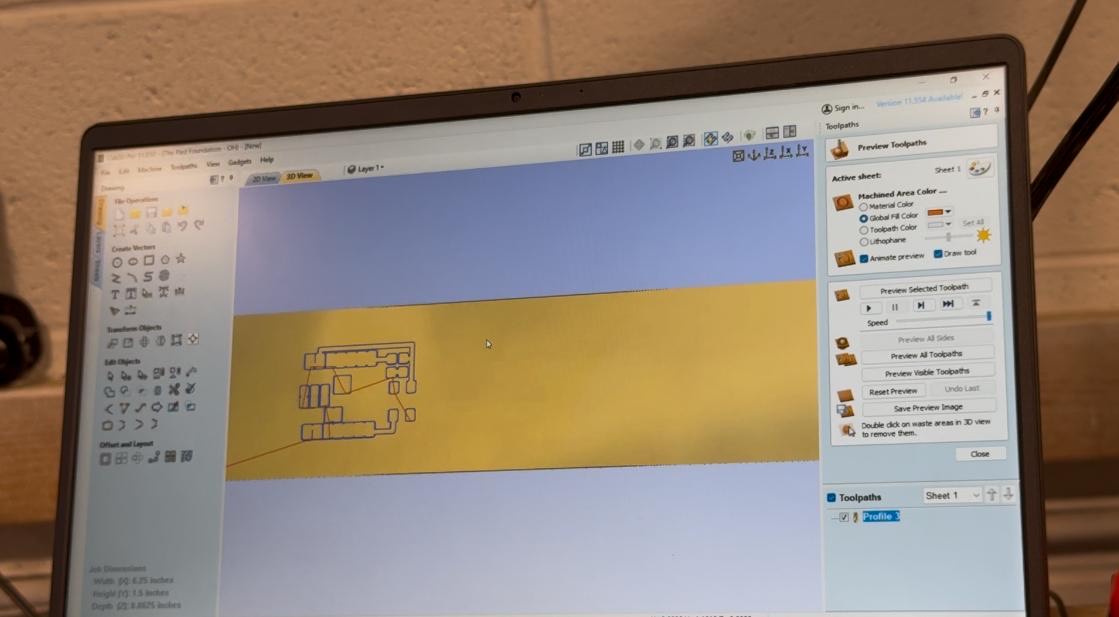
Using CNC Milling for PCB Fabrication
Due to the limitations of laser cutting, CNC milling was used to create the PCB. We opted for the Forest Scientific ATC (auto tool changer) to assist us with this process.
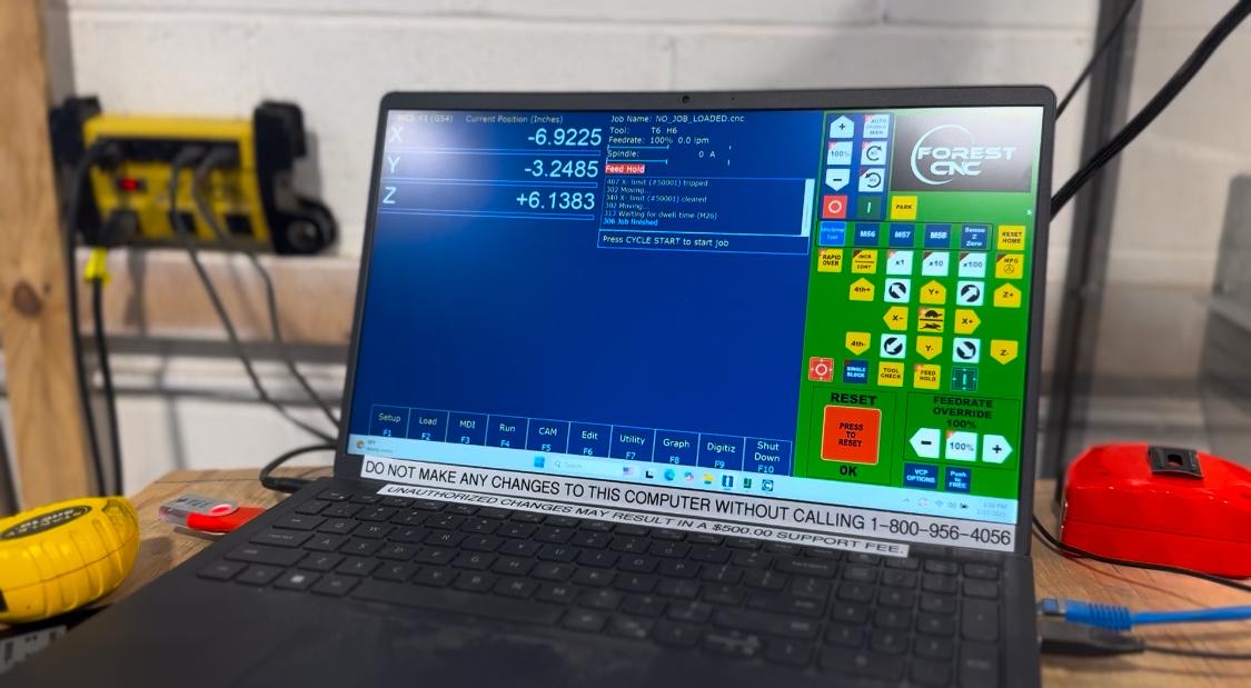
Zeroing the X, Y, and Z Axes in CNC Milling
When using CNC milling, it was crucial to properly zero the X, Y, and Z axes before starting the milling process. Zeroing ensures that the machine knows the exact starting point, preventing misalignment and material wastage. The X and Y axes were set to define the origin of the PCB layout, while the Z-axis was carefully adjusted to control the cutting depth. Incorrect zeroing can lead to shallow cuts, which may not fully engrave the traces, or deep cuts, which can damage the board. By accurately zeroing all three axes, we ensured precise milling and a functional PCB.
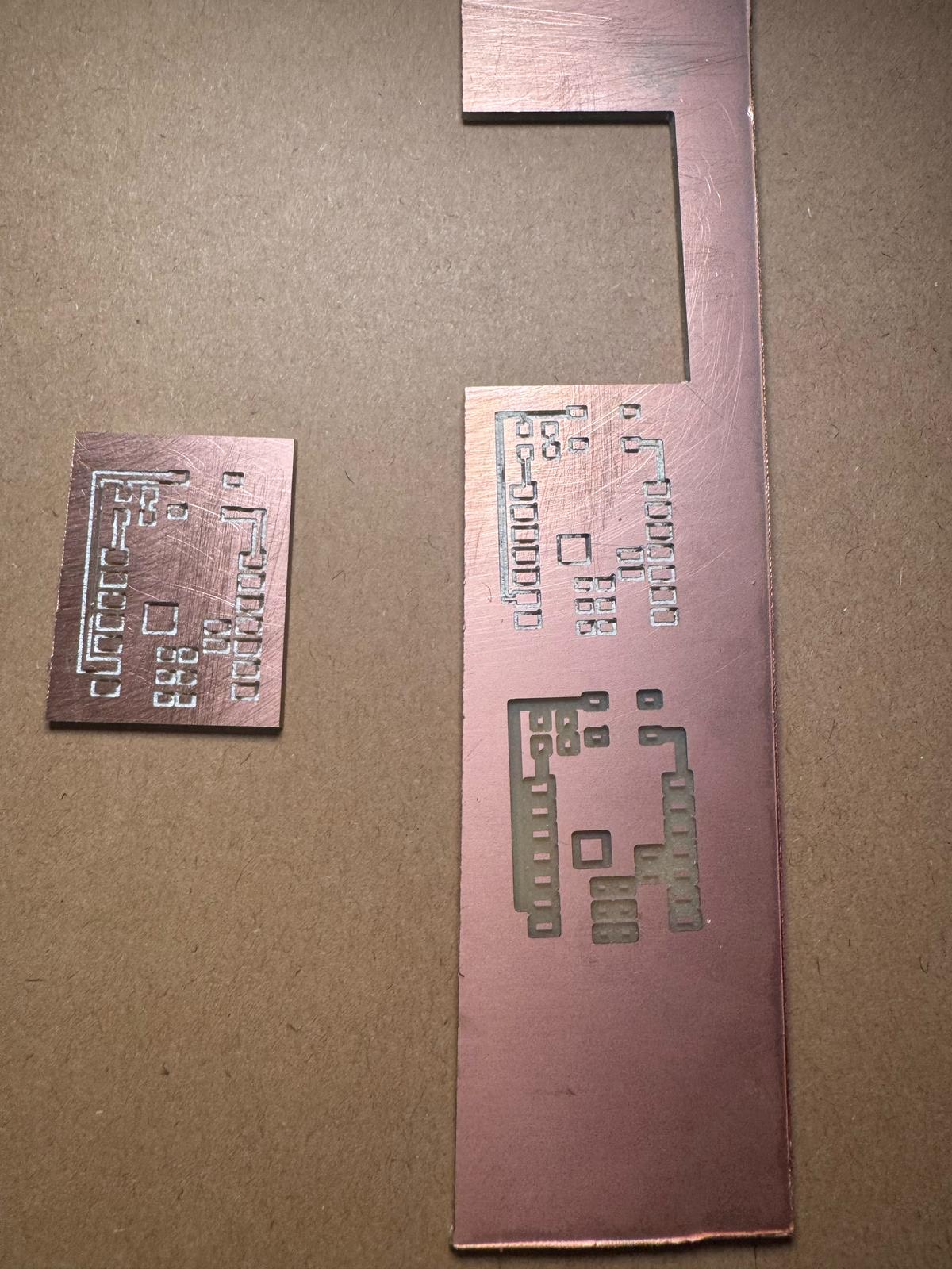
- First Iteration: The drill bit did not ptovide ample penetration, resulting in incomplete traces.
- Second Iteration: The drill bit was set too deep, causing overcut traces that compromised the circuit.
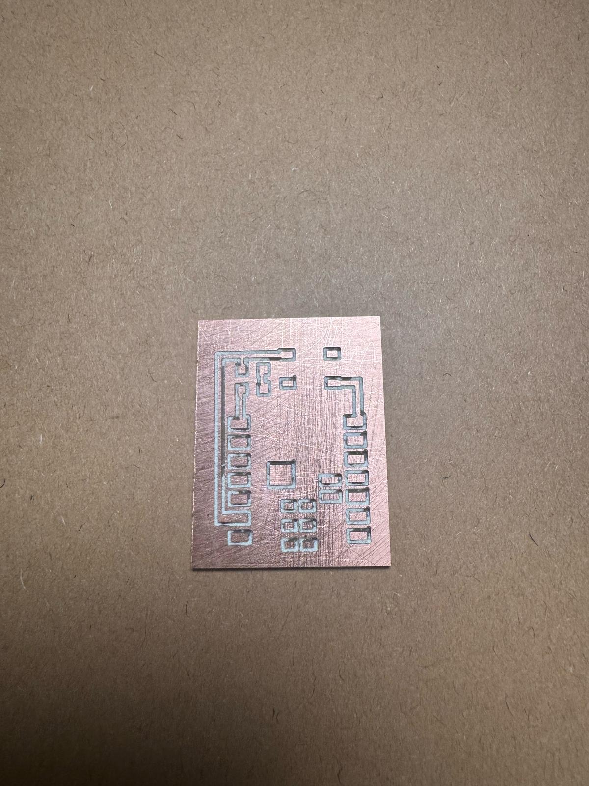
- Third Iteration: A finer-tipped drill bit was used, and the schematics were updated. This resulted in a successful PCB with well-defined traces.
- Finalize PCB assembly once components arrive and/or locate electronics store.
- Solder the button and other necessary components onto the PCB.
- Test the microcontroller’s interaction with input/output components.
- Program the microcontroller to establish remote communication.
- Document the results, including challenges faced and solutions implemented.
Component Availability and Testing
For testing, a button needs to be soldered onto the PCB. However, the lab currently does not have buttons or sensors in stock. Orders have been placed for the necessary components, and testing will be finalized as soon as the parts arrive.
Conclusion
Research
This is where I will be documenting my work as I progress through the FabAcademy and the weekly projects. amet, E.
"Lorem ipsum dolor sit amet, consectetur adipiscing elit, sed do eiusmod tempor incididunt ut labore et dolore magna aliqua. Ut enim ad minim veniam, quis nostrud exercitation ullamco laboris nisi ut aliquip ex ea commodo consequat. Duis aute irure dolor in reprehenderit in voluptate velit esse cillum dolore eu fugiat nulla pariatur. Excepteur sint occaecat cupidatat non proident, sunt in culpa qui officia deserunt mollit anim id est laborum.documentation
Useful links
Code Example
  // the setup function runs once when you press reset or power the board
  void setup() {
    // initialize digital pin LED_BUILTIN as an output.
    pinMode(LED_BUILTIN, OUTPUT);
  }

  // the loop function runs over and over again forever
  void loop() {
    digitalWrite(LED_BUILTIN, HIGH);   // turn the LED on (HIGH is the voltage level)
    delay(1000);                       // wait for a second
    digitalWrite(LED_BUILTIN, LOW);    // turn the LED off by making the voltage LOW
    delay(1000);                       // wait for a second
  }
Gallery

Video
From Vimeo
Sound Waves from George Gally (Radarboy) on Vimeo.
From Youtube