Embedded Programming
Individual Assignment
Comparison: ESP32 vs. RP2040 vs. SAMD21
Similarities
- All three microcontrollers support programming with Arduino and MicroPython.
- They are widely used in embedded systems, IoT applications, and low-power designs.
- Each microcontroller has GPIOs for interfacing with sensors and peripherals.
Differences
- Processing Power:
- ESP32 has a dual-core Xtensa LX6 processor running up to 240 MHz.
- RP2040 has a dual-core Cortex-M0+ running at 133 MHz.
- SAMD21 has a single-core Cortex-M0+ running at 48 MHz.
- Memory:
- ESP32 has 520KB SRAM and supports external flash.
- RP2040 has 264KB SRAM and 2MB onboard flash.
- SAMD21 has 32KB SRAM and 256KB flash storage.
- Connectivity:
- ESP32 has built-in Wi-Fi and Bluetooth.
- RP2040 and SAMD21 lack native wireless connectivity.
- Power Consumption:
- ESP32 consumes more power due to its Wi-Fi and Bluetooth capabilities.
- RP2040 is more power-efficient but does not have built-in connectivity.
- SAMD21 is optimized for ultra-low power consumption.
- USB Support:
- ESP32 has native USB-to-serial communication.
- RP2040 supports USB device and host modes.
- SAMD21 has built-in USB support.
Research
Using WOKWI to Program a Microntroller
Create an Account
- Go to Wokwi.com
- Create an account if needed
- Click “New Project”
- Select Arduino Uno
Components Used:
- Wokwi Online Simulator
- Arduino Uno
- Pushbutton (digital input)
- Built-in LED (digital output)
Step-by-Step Instructions
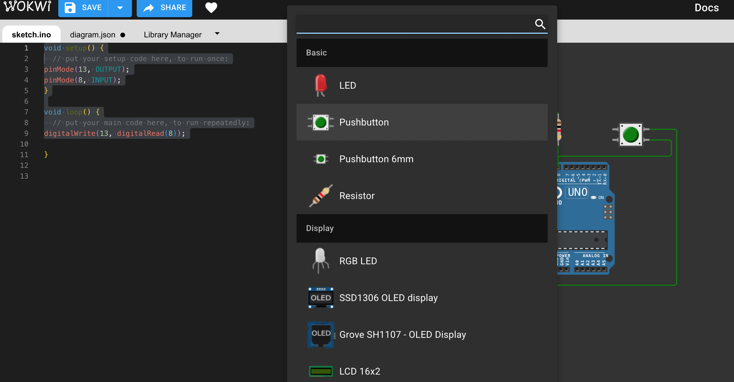
2. Add a Pushbutton
- Click the purple ➕ button
- Search and select Pushbutton
- Drag it into the workspace
3. Connect the Button
- Left leg of the button → GND
- Right leg of the button → D8 on Arduino
- (Optional) Add a pull-up resistor, or rely on Arduino’s internal pull-up (code handles it)
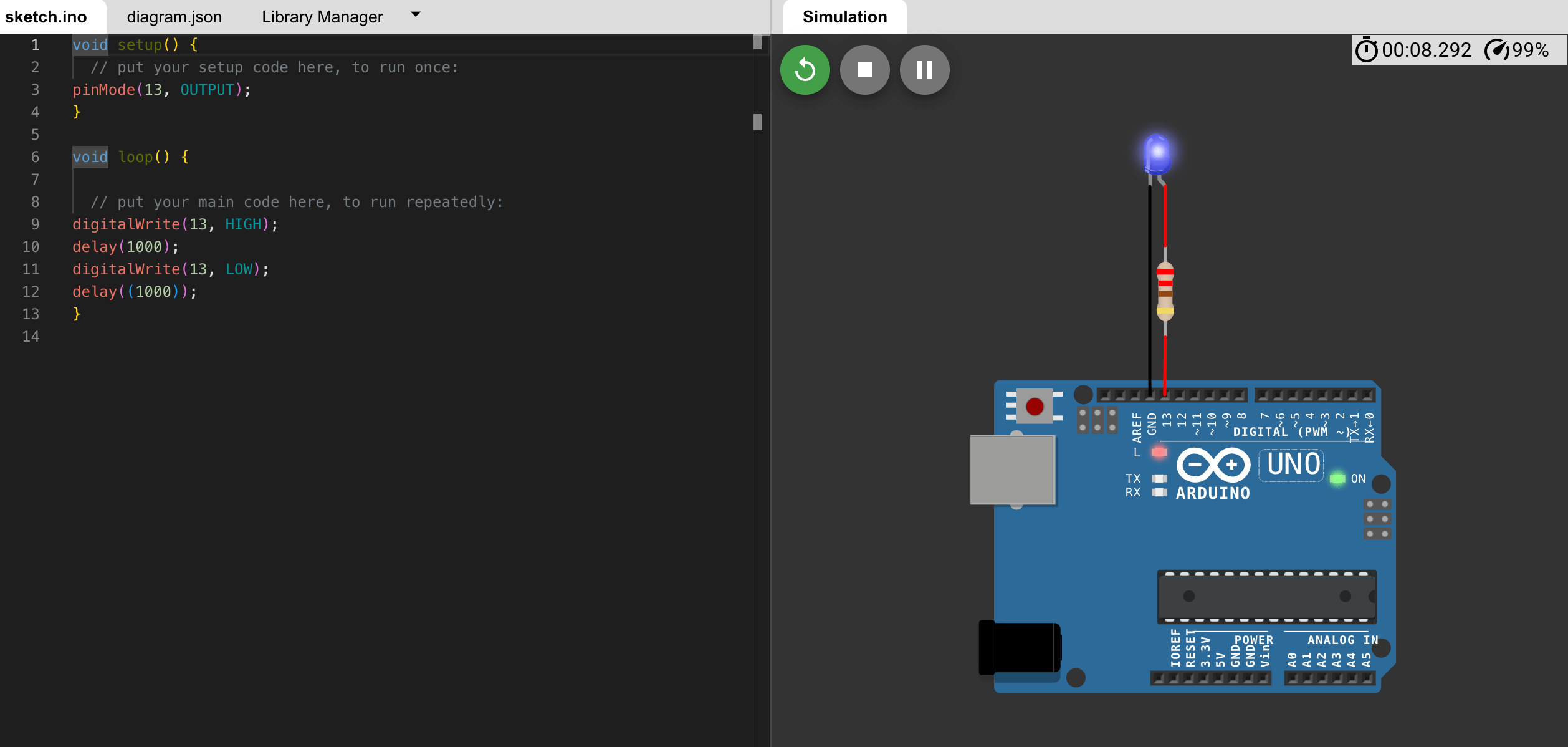
How it Works:
- The Arduino continuously reads the input from pin 8 (pushbutton).
- It mirrors that state to pin 13.
- When the button is pressed, pin 8 reads HIGH, and the LED on pin 13 turns ON.
- When not pressed, pin 8 reads LOW, and the LED turns OFF.
Project Files:
xyzReflection on Group Assignment:
Prompt: Demonstrate and compare the toolchains and development workflows for available embedded architectures.
This project helped me understand how digital pins work as inputs and outputs. It also showed me how to directly mirror an input pin to an output pin using basic embedded programming logic.
Comparison:
- Arduino Uno: Easy to use, great for beginners, lots of community support
- RP2040: Faster, more powerful, flexible with MicroPython or C/C++
- ??? (Insert third platform of your choice to compare)