Week 4 - Embedded programming
This week, Toni gave us a clarifying tutorial on embedded devices and programming. For our group work with Stanley and Shahmeer, our task was to demonstrate and compare the toolchains and development workflows for different embedded architectures. The main programming language options are:
- MicroPython – A version of Python optimized for microcontrollers. It's less efficient than C/C++ but easier to use as a high-level language. Python is real-time and interactive, making it easier to test and retrieve data instantly. For example, if a temperature sensor is connected to a microcontroller, you can immediately read its value in Thonny without needing to compile or upload code.
- Arduino - Uses a C/C++-based language, which results in faster execution because it is compiled, whereas MicroPython is interpreted. Compared to standard C/C++, Arduino sacrifices some flexibility and control for ease of use. It's still more complex than MicroPython and not a real-time system, but it offers excellent documentation and many online examples. Unlike the above example, when using Arduino, you must write code to read the temperature, compile it, and upload it to the microcontroller for execution.
Considering my final project, it seems that a C++-based microcontroller is the better choice. My final project is a fast-paced game, requiring the embedded software to be as responsive as possible. If a Python-based microcontroller were too slow for my needs, switching to C++ later would mean rewriting the entire code.
To determine which microcontroller to use, I started with one of the most popular choices: the Raspberry Pi Pico. It features the RP2040 chip, a dual-core Arm Cortex-M0+ processor running at 133 MHz, with 264kB internal RAM and support for up to 16MB of off-chip flash memory. The RP2040 itself costs less than €1, while the Raspberry Pi Pico board is available for under €10, offering impressive capabilities for its price.
In my final project, I plan to have the following outputs from the microcontroller: fan speed control, baseball bat servo motor control, target angle servo control and several 8-segment displays. On the input side, I plan to include four simple inputs: start button, two game buttons and one sensor from the target.
The Pi Pico provides 30 GPIO pins, four of which can be used as analog inputs. This should be sufficient for my application.To check for better alternatives, I asked ChatGPT: "Which microcontroller is best for a simple pinball-like game with four buttons, 12 8-segment displays, and two servo motors, where the game score needs to be saved in non-volatile memory?" the ESP32 was recommended over the Raspberry Pi Pico. The main advantages mentioned were: Built-in WiFi & Bluetooth (which could allow me to create a histogram of game scores on this web page), better support for TM1637 and MAX7219 (which allow multiple 8-segment displays to be controlled with fewer data lines, making wiring easier) and support for EEPROM emulation and SD cards (good for storing game scores).
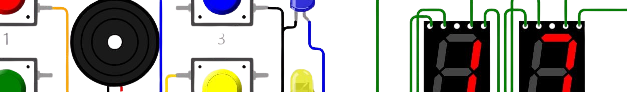
Despite this, I first attempted to simulate the basic game performance on wokwi.com using the Pi Pico. My initial goal was simply to display a number that increases with each button press. Eventually, I plan to replace the button with a sensor from the target in my game project. I found examples similar to what I was trying to achieve, but for some reason, the following code did not work. This is likely what ChatGPT was referring to earlier - using a TM1637-based display with a Pi Pico is not entirely straightforward, adding TM1637Display.h library was unsuccessful. Troubleshooting this was difficult due to the slowness of the Wokwi online simulator.
The unworking Wokwi simulation circuit:
Unworking code for Pi Pico:
			//almost the same as https://wokwi.com/projects/312696687190606401
			//Copyright (C) 2021, Uri Shaked. Released under the MIT License.
			#include "pitches.h"
			#include "TM1637Display.h" //required for the TM1637 seven segment display
			#include  //needed for OLED and Graphical LCD Displays (I2C/SPI)

			#define CLK 10  // Clock pin
			#define DIO 9   // Data pin

			TM1637Display display(CLK, DIO);

			#define SPEAKER_PIN 8

			#define gameStart 0
			#define gameEnd 1
			#define gamePlaying 2

			volatile int gameStatus = gameStart;

			const uint8_t start_button = 4;
			const uint8_t button1 = 5;
			const uint8_t button2 = 6;
			const uint8_t score_button = 7;
			uint8_t MyScore = 1;

			const int buttonTones[] = {
			NOTE_C4, NOTE_D4, NOTE_E4, NOTE_F4,
			NOTE_G4, NOTE_A4, NOTE_B4, NOTE_C5
			};

			void setup() {
			Serial.begin(9600);
			pinMode(start_button, INPUT_PULLUP);
			pinMode(button1, INPUT_PULLUP);
			pinMode(button2, INPUT_PULLUP);
			pinMode(score_button, INPUT_PULLUP);
			pinMode(SPEAKER_PIN, OUTPUT);
			}

			// Display the score on the 7-segment display
			void ShowScore() {
			display.showNumberDecEx(MyScore, 0b01000000, true);
			}

			void loop() {
			ShowScore();

			if (digitalRead(score_button) == LOW) {
			MyScore += 1;
			int pitch = buttonTones[MyScore % 8];
			tone(SPEAKER_PIN, pitch, 200);
			delay(300);
			}

			delay(10);
			}
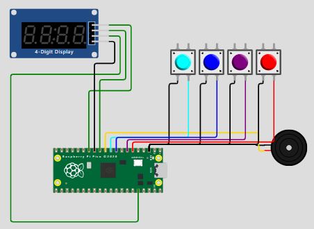
I decided to try with the ESP32. Again, I found a useful example on Wokwi.com, which I modified just slightly to get the bare minimum operation I was looking for. This is the Wokwi simulation result:
Working code for the ESP32:
			// Based on https://wokwi.com/projects/372153001566564353

			// Removed: playSequence(), gameOver(), checkUserSequence(), playLevelUpSound()
			// Simplified the code to function as a basic counter
			// Serves as a starting point for implementing my project

			// Copyright (C) 2023, Uri Shaked. Released under the MIT License.

			#include "pitches.h"

			/* Define pin numbers for LEDs, buttons and speaker: */
			const uint8_t buttonPins[] = {0, 1, 2, 3};
			const uint8_t ledPins[] = {8, 7, 6, 5};
			#define SPEAKER_PIN 10

			// These are connected to 74HC595 shift register (used to show game score):
			const int LATCH_PIN = 18;  // 74HC595 pin 12
			const int DATA_PIN = 19;   // 74HC595 pin 14
			const int CLOCK_PIN = 9;  // 74HC595 pin 11

			#define MAX_GAME_LENGTH 100

			const int gameTones[] = { NOTE_G3, NOTE_C4, NOTE_E4, NOTE_G5};

			/* Global variables - store the game state */
			uint8_t gameSequence[MAX_GAME_LENGTH] = {0};
			uint8_t gameIndex = 0;

			/**
				Set up the Arduino board and initialize Serial communication
			*/
			void setup() {
				Serial.begin(9600);
				for (byte i = 0; i < 4; i++) {
				pinMode(ledPins[i], OUTPUT);
				pinMode(buttonPins[i], INPUT_PULLUP);
				}
				pinMode(SPEAKER_PIN, OUTPUT);
				pinMode(LATCH_PIN, OUTPUT);
				pinMode(CLOCK_PIN, OUTPUT);
				pinMode(DATA_PIN, OUTPUT);
			}

			/* Digit table for the 7-segment display */
			const uint8_t digitTable[] = {
				0b11000000,
				0b11111001,
				0b10100100,
				0b10110000,
				0b10011001,
				0b10010010,
				0b10000010,
				0b11111000,
				0b10000000,
				0b10010000,
			};
			const uint8_t DASH = 0b10111111;

			void sendScore(uint8_t high, uint8_t low) {
				digitalWrite(LATCH_PIN, LOW);
				shiftOut(DATA_PIN, CLOCK_PIN, MSBFIRST, low);
				shiftOut(DATA_PIN, CLOCK_PIN, MSBFIRST, high);
				digitalWrite(LATCH_PIN, HIGH);
			}

			void displayScore() {
				int high = gameIndex % 100 / 10;
				int low = gameIndex % 10;
				sendScore(high ? digitTable[high] : 0xff, digitTable[low]);
			}


			void lightLedAndPlayTone(byte ledIndex) {
				digitalWrite(ledPins[ledIndex], HIGH);
				tone(SPEAKER_PIN, gameTones[ledIndex]);
				delay(300);
				digitalWrite(ledPins[ledIndex], LOW);
				noTone(SPEAKER_PIN);
			}


			/**
				Waits until the user presses one of the buttons,
				then lights up corresponding LED, plays sound and increases variable gameIndex
			*/
			void read_buttons() {
				for (byte i = 0; i < 4; i++) {  // Loop through all buttons
				if (digitalRead(buttonPins[i]) == LOW) {  // If any button is pressed
					lightLedAndPlayTone(i); // different functions are not yet defined for different buttons
					gameIndex += 1;  // Increase the score
					Serial.println("Score!");
					delay(200);  // Debounce delay to avoid multiple counts from one press
					return;  // Exit the function after the first button press
				}
				}
			}


	/**
		The main game loop, made this much simpler
	*/
	void loop() {
		displayScore();
		read_buttons();
	}
Update after week 4
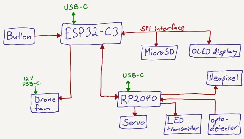
For my final project, I decided to use two Seeed Studio XIAO ESP32-C3 mini development boards, which are based on the Espressif ESP32-C3. This ultra-low-power SoC features a single-core RISC-V CPU running at up to 160 MHz, 400 kB of SRAM, built-in Wi-Fi and Bluetooth 5 support, and advanced peripheral interfaces. The development board provides 11 PWM-capable digital pins and 3 analog input/output pins. This setup gives me a sufficient number of I/O pins and enables a modular system design: board #1 handles most of the game logic, as shown in the diagram below, while board #2 controls the target loop mechanism.
I relied heavily on the help of ChatGPT to write the code for the game. I first coded the different subsystems and then combined them to make the whole game operate, and iterated to make it better. Below are the various subsystems, each accompanied by the ChatGPT prompts that helped me produce functional code.
1. Button and Fan (PWM Control, Game Input)
In my final project, I used a drone motor that requires a PWM signal with a 1 ms pulse width and a frequency of 50 Hz to initialize. Once this signal is received, the motor beeps in a specific sequence and becomes operational, with its RPM controlled by the pulse width. I successfully implemented this using the following prompts, where the pulse width gradually increases when a button is pressed and slowly decreases back to 1.2 ms (corresponding to 0 RPM) when the button is released.
- I need an Arduino IDE program for an ESP32-C3. There is just one button... (includes countdown timer, score pulses, PWM control, servo angle)
- I want to drive an ESC drone. Create Arduino IDE for simple PWM control, low PWM output
- The fan pulseWidth should be 1000 ms and then go to 1200 ms and not go below 1200 after that
- OK now this works almost perfect, but when the timer goes to 0 the fan PWM also goes to 0 for some time.
- Could there be a 50 Hz pulsing with 1 ms width for a duration of one second in the beginning so the ESC starts up?
- On now the servo angle works as it's supposed to! But the 50 Hz signal pulse width should be 1 ms first to start up the ESC and then when the button is pressed, the pulse width increases slowly from 1.2 ms up to a maximum of 1.5 ms, and decreases back when not pressed.
2. Optical Gate (Input Detection, Board 2)
I used synchronous detection to ensure reliable operation of the optical loop. An LED on one side of the target loop rapidly turns on and off, while a phototransistor on the opposite side detects the light signal along with any ambient light. By measuring the phototransistor’s output when the LED is off, I can determine the ambient light level. This value is then subtracted from the signal measured when the LED is on, effectively filtering out background light and preventing false detections caused by changes in ambient lighting. ChatGPT prompts:
- I need to detect when a ping pong ball goes through a loop. Can I make it digital or is analog better?
- Xiao ESP32-C3 #2 is sending a pulse every time a ball has gone through a loop with the following: (code included)
- Working really nicely except not getting all the score pulses? Should the pulse be wider or what could help?
- No, now the score just keeps rapidly growing
- Still score just keeps increasing with these: (code included)
- I changed main board to #define PULSE_PIN 6 // Input pin to receive pulse (must support interrupts)
- So I am using just one GPIO from board #2 to send a pulse to board #1. Could board #1 communicate via this same GPIO towards board #2 that the game has ended?
3. Servo Motor (Scoring Animation)
The servo motor starts at an angle of 90°, which corresponds to the upright position of the target loop. Each time a score is made, the angle decreases toward 0°, then returns to 90°, and this cycle repeats with each subsequent score. The following ChatGPT prompts were used to implement this behavior.
- How about driving a servo?
- I have a servo connected to ESP32-C3. Is it easy to make a program that controls the servo angle?
- Can the servo turn slower?
- The servo should start from 90, and when there is a score it moves slowly to 80 and stays there until there is another score, then goes to 70 and so forth.
- No, starts from 90, then moves slowly to 80 → 70 (down by 10° each time), then up again
- The screen stops working when the servo moves. Could it be drawing too much current from the 5 V?
- At the end of the game the servo should go back to 90
- Is there a command to read the servo angle?
4. OLED Display (Visual Feedback)
I wanted to orient the screen vertically so that the timer, score, ranking, and total number of games could be displayed as large numbers stacked vertically. To achieve this layout, I manually adjusted the coordinates of each element through trial and error until they appeared in the desired positions. Below are the ChatGPT prompts I used to implement this setup.
- How about to drive a simple OLED screen?
- How do I use Hailege 2.42" SSD1309 OLED display SPI with ESP32-C3?
- Compilation error: U8g2lib.h: No such file or directory
- Font size alternatives u8g2_font_ncenB48_tr
- Loop write from 0 to 99 every 0.2 s: u8g2.drawStr(0, 54, "0");
- Maybe every 1 second the screen jitters
- So what's the best way to improve this: [includes u8g2 loop code with number display]
- Stopped working, just showing empty OLED?
- At the end of the game: the OLED screen Last game points x, Ranking x, Press to start
5. MicroSD (Score Tracking, Game History)
I decided to store the scores on the microSD card as a simple histogram, where each score increments the corresponding bin. For example, a score of 5 increases the count in bin 5. This makes it easy to calculate the ranking and total number of games in real-time during gameplay. These are the prompts I used with ChatGPT.
- Where should I store game scores?
- At the end of each game the score is written in memory
- I would like a histogram of scores on the microSD. Range of scores is from 0 to 100.
- The display shows real-time ranking: x / y, where y is total number of games
- So if 5 games have been played, the next game starts with rank 6 and updates
- If the ranking is a tie, the lowest of equal scores is used
6. NeoPixel (Visual Feedback, Board 2)
Each time the ball passes through the gate, a NeoPixel embedded inside the target loop lights up briefly. Through trial and error, I found an appealing pattern of colors with adjusted durations and brightness levels.
- I have an ESP32-C3 and I want to drive NeoPixels with it.
- Shared full Arduino sketch using NeoPixels and IR LED sensor
- This always flashes about five times?
- I am using code in board #2 to light up the target green at each score and send a pulse to board #1. Could I turn the light red when the game ends?
7. Communication Between Boards
I decided to have a very simple communication between the two boards so that board #2 simply transmits a pulse to board #1 each time a score is detected.
- I have two ESP32-C3s in my project. The second one sends a signal to the first. How should I transmit the signal? a
- Can I have an ESP32-C3 connected to SPI displays and MicroSD through routed pins?
- Is it easy to do SPI communication between two ESP32-C3s?
8. Complete Code Integration / Final Project Logic
Once the subsystems were functional, I used ChatGPT to help integrate them efficiently into a unified program.
- Can you integrate this into the main code?
- When the timer goes to 0 the PWM also goes to 0 briefly
- On button press, the servo moves through 90° → 80° → 70° and so forth
- Real-time ranking and total number of games should show on display
- At the end, wait for button press to restart the game
Below is a video of the display working as expected. More display and software operation can be seen in the final project video.
Design files
Final project board #1 code: button input, drone fan PWM modulation, servo PWM output, SPI communication with MicroSD and OLED display, input pulse from board 2.
Final project board #2 code: Optogate, neopixel output, pulse output to board 1.