Week 2 - Computer aided design
This week’s assignment was to model a possible final project using various techniques such as raster and vector graphics, 2D and 3D modeling, rendering, animation, and simulation. Below, I document my progress and learnings.
2D raster graphics
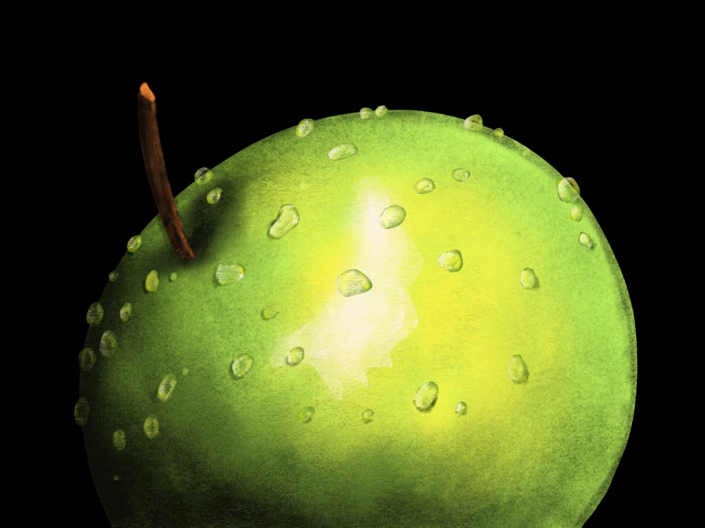
For raster graphics, there are several alternatives, including GIMP (free) and Photoshop. Recently, I watched several YouTube tutorials on Procreate for iPad, such as this one. Below is my output based on the tutorial, along with a few key takeaways:
- Fill with color by dragging in the color circle.
- Warp tool is in the arrow menu.
- Add layers from the top-right menu (+ sign).
- Shading, highlighting, and smudging tools are in the brush menu (upper-right corner).
- Brush size is adjusted using the upper slider on the left side.
- Selection tool (S-looking icon in the top left) lets you select regions.
- Color picker: Press and hold a finger on the screen.
- Editing water droplets is easier when they are on their own layer.
- Shading can be applied by choosing the layer of the apple.
2D vector graphics
Unlike raster graphics, vector graphics use lines instead of pixels, making them ideal for laser cutting. While I am proficient in MS Visio, I will use Inkscape for this course, as it is a widely used, free vector graphics software.
I watched a basic tutorial on Inkscape. Here are some useful, non-obvious takeaways I gathered from the video:
- The Bézier curve tool works by long-pressing the mouse button to create curved vector line edges.
- Text boxes can be created with the "A" tool by long-pressing the mouse button.
- Hold the space bar to pan around.
- Snap modes can be toggled on/off using the button in the upper-right corner that looks like a magnet.
- Rectangle edges can be curved by double-clicking the rectangle, then clicking and dragging an edge point downward.
- Shapes like text or stars can be converted to paths via Object > Convert to Path, removing shape limitations.
- Use Path > Trace Bitmap to convert an image into a vector (single or multicolor options available).
- In Layers and Objects, the order of objects in a layer determines which color object appears on top.
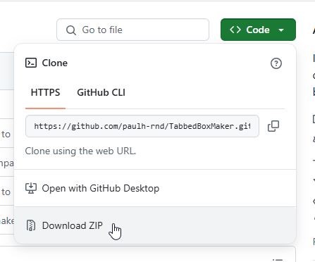
I also tried TabbedBoxMaker, a free Inkscape extension for generating tab-jointed box patterns. It accounts for kerf (the width of material removed by the laser cutter) and allows for dividing sections within the box if needed. The zip file download link on the main page does not work, but this one does:
The extension was installed by first locating the Inkscape extensions directory in Inkscape > Edit > Preferences > System. The extension files were then copied into that directory. After this, Inkscape needed to be restarted for the extension to appear under Extensions > CNC Tools.
I then had to significantly increase the default canvas size to accommodate the tab-jointed box edges for my intended final project, which measures 800 mm × 400 mm × 600 mm (more on the reasoning for this size later). This was adjusted in File > Document Properties.
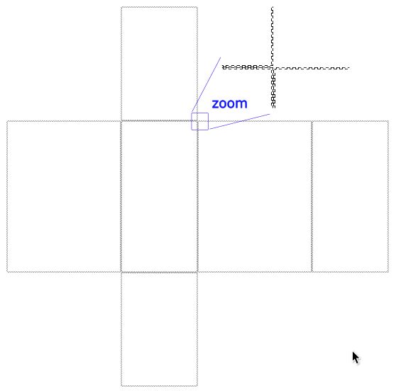
After this, generating the tab-jointed box patterns was straightforward, resulting in the following outcome:
3D modeling & rendering
For 3D modeling, the main alternatives are:
- Fusion 360 (free, except for large-scale commercial production)
- FreeCAD (free, but not as intuitive as Fusion 360)
- Onshape (simple, browser-based, but all designs are public)
Blender
For 3D rendering and animation, Blender is a nice free option. After modeling in Fusion 360, FreeCAD, or Onshape, Blender can be used to create high-quality visuals.
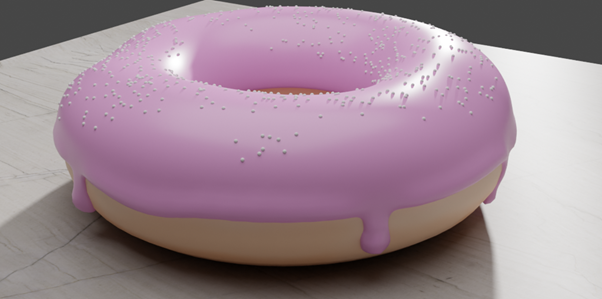
Previously, I followed along with the well-known Blender Donut Tutorial and produced the following result, which is not as refined as it could be. The process was quite extensive, with too many steps to document here.
Fusion 360
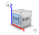
For 3D modeling my final product, I’m using Fusion 360, for which I had a nice tutorial from Gleb. In the program, we mainly work in the Design tab. The 3D view can be rotated with Shift + middle mouse button and panned with the middle mouse button alone. The scroll wheel zooms into the area where the cursor is positioned. The following cube is also useful for selecting different perspectives, such as viewing exactly along the X-plane. The home button next to the cube is good if you get lost spinning and zooming.
Free Orbit was chosen and Camera Pivot disabled in the preferences (the icon that looks like a face in the upper right corner).
In the lower-left corner, we have the Timeline, which is more powerful than the usual undo command. Instead of just undoing steps, you can go back in the design history, make changes (e.g., adjust a dimension), and then "go back to the future" - where the past changes automatically update in the present. You can also double-click on a feature in the Timeline to easily select and modify it
I started my 3D model of the final project in Fusion 360 by first considering the physical size of the game. Since a ping pong ball has a diameter of 40 mm, I estimated that the game could fit within a space of 800 mm (width) × 400 mm (depth) × 600 mm (height). As a base, I created a solid board with a height of -5 mm by drawing a box in Fusion 360.
I'll probably use a computer fan to float the ball. A common standard size for these is 120 × 120 × 25 mm, so I initially modeled it as a simple box with a hole through it. This component will be shown in later images. I created this by:
- Sketching a 120 × 120 mm square in Sketch Mode.
- Extruding it by 25 mm in the Z-direction to form a box.
- Drawing a circle on the top surface using the sketching tool.
- Extruding the circle downwards to cut a hole through the box.
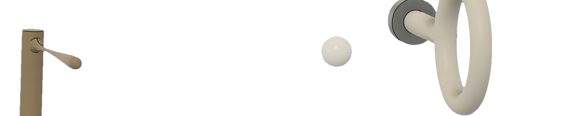
Next, to create a 3D baseball bat, I first sketched a 2D closed profile of the bat:
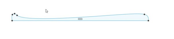
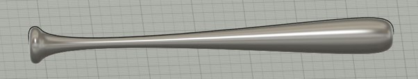
Next, in the Solid tab, I used the Create → Revolve tool to turn the 2D bat profile into a 3D object. I selected the closed sketch profile of the bat as the shape and defined the center axis for the revolution. By revolving it 360 degrees, the bat took its final 3D form:
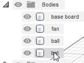
I'm renaming all these bodies as I create them to maintain clarity and make the model easier to manage:
I decided to create a separate component for the plastic part that will sit on top of the fan (shown from above and below in the next image). This allows me to 3D-print just this component first to test whether the ping pong ball floats as expected. If the floating mechanism doesn't work well, I can later modify this component accordingly. According to ChatGPT, a ping pong ball stays on top of a fan due to aerodynamic forces, primarily the Bernoulli principle and the Coandă effect.

To create the above component, I first selected a plane for sketching. If the sketch wasn't on the default X, Y, or Z planes relative to the origin, I used a floating offset plane to position it correctly.
I then sketched the shape—usually a square or a circle—added constraints to control its position (e.g., centering it or ensuring it remains tangent to another sketch or component), and finally used extrusion to either add or remove 3D mass. I encountered more difficulty than expected when trying to create constraints.
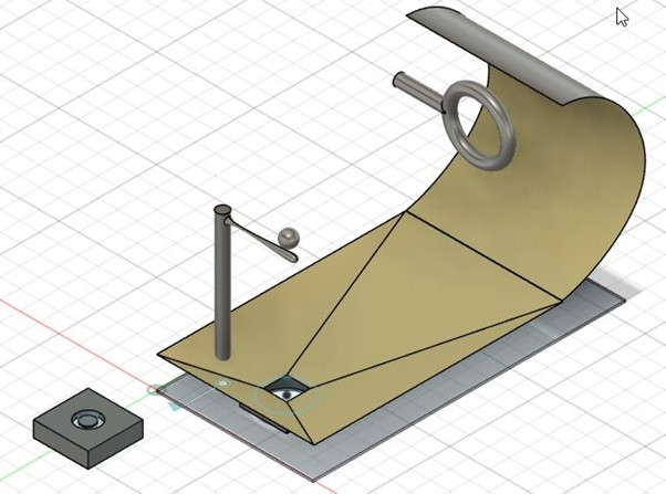
For the ping pong ball target, I combined a torus and a cylinder. For the ball return, I first sketched its shape on the Y-Z plane (shown in the following image) and then extruded this sketch along the X-direction. The resulting gold-colored 3D model can be seen in the image after this.
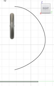
For the ball to return nicely to the ball launching tray nicely, there needs to be a downward hill from all sides. For this, I created a small blue square sketch above the launching tray, and a large blue square sketch above this:
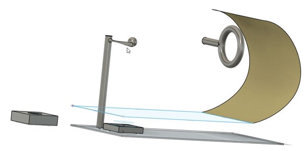
Next, I used the Loft tool in the Surface tab to smoothly connect these squares in three dimensions.
Next, I created a revolving joint between the bat body and the base body. Here is a timeline video of the design:
I then animated the intended game operation using the Animation tab in Fusion 360. The animation was built step by step by adjusting the time frame, transforming components (moving and rotating) using the M key shortcut, and confirming each movement by pressing OK.
Image and video compression
Since our total repository limit is 500 MB, we need to heavily compress videos and use small images on our web pages. To reduce the videos on this page to 400 pixel width and to use H.264 (good compression, widely supported) I downloaded ffmpeg and used the following command in the terminal to reduce the file sizes to just a few hundred kilobytes. For example, the size of the video with the green apple went down from 3.9 MB to 356 kB.
ffmpeg -i input_video -vcodec libx264 -crf 25 -preset medium -vf scale=400:-2 -acodec libmp3lame -q:a 4 -ar 48000 -ac 2 output_video.mp4
As explained in Week 1 description, I used Microsoft PowerToys (available on the Microsoft Store) to resize images.