8. Electronics Production
group assignment:
- characterize the design rules for your in-house PCB production process
- submit a PCB design to a board house
individual assignment:
- make and test a microcontroller development board that you designed
- extra credit: make it with another process
group assignment:
1.Learn about PCB
This week we are learning to make circuit boards, and we are using the Roland SRM-20 CNC machine. The SRM-20 is a compact subtractive manufacturing machine that transforms a digital model directly into a solid part using Computer Numerical Control (CNC) technology, supporting a wide range of materials such as ABS, acrylic, wood, and soft metals, making it suitable for making high-precision prototypes or functional assemblies. The software we use is VPanel for SRM-20.

We use 1.7MM thickness copper plate, we use 0.4MM milling head for engraving the plate, and we use 0.8mm milling head for cutting the outer contour.

2.Preparing files for cutting
Next my teacher Saverio and I started to test the cutting results of the CNC machine, we found the test file on this website .

3. Set processing parameters using mods
-
Setting up images on the modsproject.org designed by Neil. Right click —— Programs —— Open Program —— SRM-20 mi11/mi11 2D PCB

-
Select png and traces, set the image, and finally output the .rml file.

-
Select png and outline, set the image, and finally output the .rml file.

4.Machine settings
-
Install the 0.4mm milling cutter, hold the cutter with your hand to prevent damage to the milling cutter head when it falls. Replace the milling cutter head by loosening the screws with a hexagonal wrench, without securing it very tightly for the time being.

-
Move the milling head to just above the center of the cutting area. Click on set origin point_XY in the software to determine the xy coordinate origin.

-
Move the milling head so that it is as close to the copper plate as possible. Hold the milling head with your left hand and use a wrench to loosen the milling head slightly. Next, while tightening the milling head with your right hand, gently push down with your left hand to prevent the milling head from moving upward while you tighten the drill bit with your right hand. Next move the milling head up and over to the area to be engraved and click on Set Z Home in the software.
(When moving down the Z-axis, be sure to move very carefully and slightly as you approach the platform.)
-
If you finish engraving the traces and next change the milling head to 0.8mm to cut the outline, you don’t need to reset the XY , but you do need to reset the Z origin.
5. CNC cutting and post-processing
-
Click on cut, clear all the old files, import test-traces.rml, next click on OUTLINE. quickly reduce the speed and watch the milling head work, then slowly increase the speed to about 80%.

-
Suck up the debris with a vacuum cleaner, wiggle the thin tool to loosen the copper, gently remove it, and then use a magnifying glass to look at your beautiful circuit board.

Congratulations, you’ve completed your first PCB.

individual assignment:
- make and test a microcontroller development board that you designed
- extra credit: make it with another process
Three steps are needed for the CNC machine to process the file
 first use the 0.4MM milling head to remove the copper around the wires,
 then use the 0.8mm milling head to cut the internal holes,
 lastly, use the 0.8mm milling head to cut the outline.

1. Convert the PCB file to *.png file
-
Add a border to the PCB file to ensure that the 3 later processed files are the same size.Only the top layer, panelized layers and multiple layers are shown.

-
Export PDF file of PCB from EASYEDA. Edit the top layer of the assembly drawing to export the same layer as in the PCB, formatted as white on black with 0 transparency.
PCB.PDF
-
Convert PDF to PNG in PS with 1000 resolution. Next in PS, select Image - Mode - Grayscale - Bitmap - Grayscale, then Fill Pattern. Converted the PCB PNG into 3 kinds of processed files in PS (traces, holes, outline), exported *.png.


-
Finally, import the 3 png images into PS and check them in layers to make sure the 3 files are machined to the correct size.
I found another way to convert PCB files into three types of images! Super efficient! (This was RICO’s suggestion—thanks a lot to him!)
- Export the PCB fabrication files (Gerber) from LCEDA website, then unzip all the files.

-
Open the GERBER2PNG website, import all the compressed files you just created, then click “Open”.

-
Quick Setup—Top Trace—Generate PNG.You can preview the image effect in the central workspace.

-
Similarly, select “Top Drill/Top Cut,” then download and save the image on the right.

2. making circuit boards with a CNC machine
-
Setting up CNC machines. A detailed description of how to commission a CNC machine is given in Teamwork, which can be viewed by clicking on group assignment.
-
Take the 3 .PNG files you just made and set them to the correct .rml format at the mods site.
traces_002_.rml
holes_pcb.rml
outline_pcb.rml -
Processing 3 times in order to create a PCB, first do the surface treatment, process the traces file, then make the internal holes, and finally cut the external outlines.
-
Use a tool with a flat top to loosen the PCB, and after carefully removing it, use a knife or other tool to make the copper wires smooth and clean, avoiding contact with neighboring wires.
3.Solder the circuit board.
-
Export material Bom,Confirm the specifications of the component. You can determine the resistance value of a chip resistor by the number on top of it. A resistor with a number of 100n is 100×10^(n), so you can calculate the resistance of 1002 is 100×10^(2)=10000Ω, and the resistance of 100Ω is 1000.

-
Apply a little bit of solder on the PCB, use the tweezers in your left hand to fix the correct component in the soldering position, and hold the heated soldering iron in your right hand to solder the tiny component.
(Remember to solder the smaller components first and the larger components last.)


4.Upload the program and test the PCB
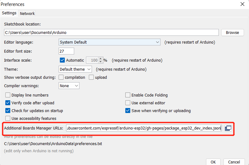
- Find File > Preferences and populate the Additional Boards Manager URLs with the following URL:https://raw.githubusercontent.com/espressif/arduino-esp32/gh-pages/package_esp32_index.json
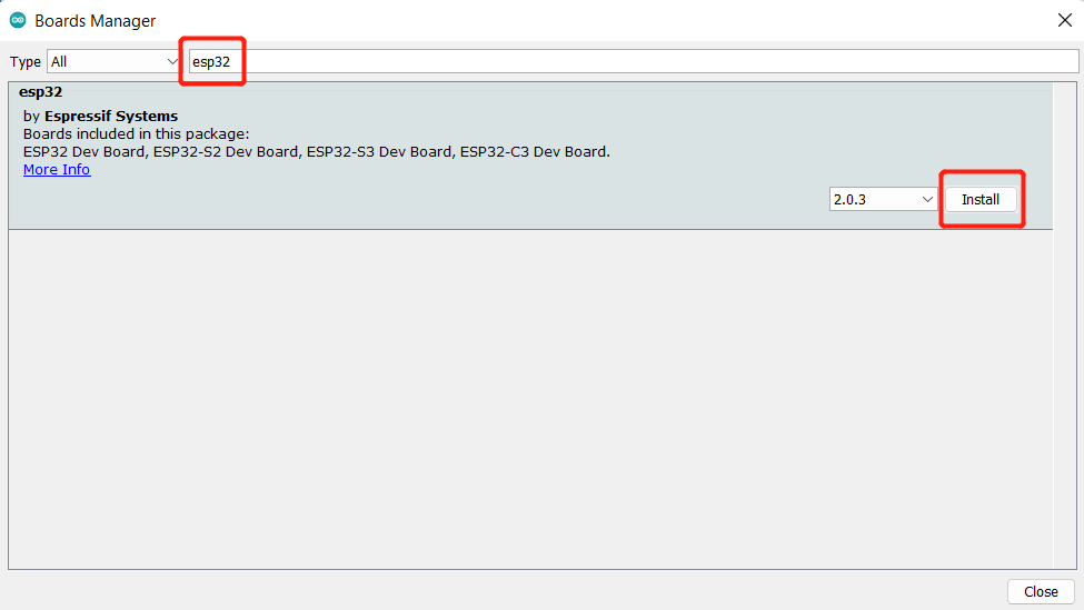
- Find Tools > Board > Boards Manager… , enter the keyword “esp32” in the search box and select the latest version of esp32 and install it , enter the keyword “esp32” in the search box, select the latest version of esp32 and install it.
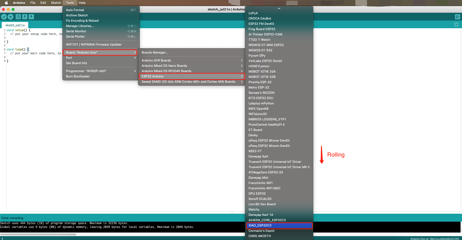
- Select your board and serial port, find Tools > Board > ESP32 Arduino and select “XIAO_ESP32C3”. The list of boards is a bit long and you need to scroll to the bottom to reach it.
-
Connect the XIAO ESP32C3 to your computer via a USB Type-C cable.Switch to Tools > Port and select the name of the connected XIAO ESP32C3 serial port. This may be COM3 or higher [My device displays: COM12 (esp32 family device)].

-
Uploading the program to the board
-
This is a simple program to blink 3 LEDs. The LEDs will turn on for 1 second and off for 1 second, repeating in a continuous loop. Through this program, it is possible to verify whether the three LED lights are functioning properly. (After verification, all three LED lights are correct)
 int led1 = D1;
 int led2 = D2;
 int led3 = D3;

 void setup() {
  pinMode(led1, OUTPUT);
  pinMode(led2, OUTPUT);
  pinMode(led3, OUTPUT);
 }

 void loop() {
  digitalWrite(led1, HIGH);
  digitalWrite(led2, HIGH);
  digitalWrite(led3, HIGH);
  delay(1000);
  digitalWrite(led1, LOW);
  digitalWrite(led2, LOW);
  digitalWrite(led3, LOW);
  delay(1000);
 }
- This is the result of my circuit board.
- Next, I designed a new program incorporating push buttons. When buttons D4/D5/D6 are pressed, LEDs D1/D2/D3 will light up accordingly. Releasing the buttons turns the LEDs off. This program verifies that both the button and LED pins are correctly configured.
// Pin Definitions
const int ledPins[] = {3, 4, 5};  // D1, D2, D3 (adjust GPIOs as needed)
const int buttonPins[] = {6, 7, 21}; // D4, D5, D6 (adjust GPIOs as needed)

void setup() {
  // Initialize LEDs as OUTPUT
  for (int i = 0; i < 3; i++) {
    pinMode(ledPins[i], OUTPUT);
  }
  // Initialize buttons as INPUT_PULLUP (active LOW)
  for (int i = 0; i < 3; i++) {
    pinMode(buttonPins[i], INPUT_PULLUP);
  }
}

void loop() {
  // Check each button and control corresponding LED
  for (int i = 0; i < 3; i++) {
    if (digitalRead(buttonPins[i]) == LOW) { // Button pressed (LOW due to pull-up)
      digitalWrite(ledPins[i], LOW); // Turn LED on
    } else {
      digitalWrite(ledPins[i], HIGH); // Turn LED off
    }
  }
  delay(10); // Debounce delay
}
- Based on my final project, I need to design a new program: one of the three LED lights will randomly light up, and if the corresponding button is pressed, the LED light will turn off. This program is a bit difficult, and in order to complete it, I relied on the help of AI.
/*
 * LED-Button Controller for XIAO-ESP32-C3
 * Features:
 * - Randomly lights one LED (D1/D2/D3) for 1 second
 * - Immediate turn-off when corresponding button is pressed
 * - Continuous cycle with only one LED active at any time
 */

// Pin Definitions
const int ledPins[] = {3, 4, 5};    // GPIO pins for LEDs D1, D2, D3
const int buttonPins[] = {6, 7, 21}; // GPIO pins for buttons D4, D5, D6

// Control Variables
int activeLedIndex = -1;             // Index of currently lit LED (-1 means none)
unsigned long lightStartTime = 0;    // Timestamp when LED was turned on
const int LED_ON_DURATION = 1000;    // Duration LED stays lit (ms)

void setup() {
  // Initialize all LED pins as OUTPUT and turn OFF
  for (int i = 0; i < 3; i++) {
    pinMode(ledPins[i], OUTPUT);
    digitalWrite(ledPins[i], LOW);   // Ensure all LEDs start OFF
  }

  // Initialize button pins as INPUT (using external pull-down resistors)
  for (int i = 0; i < 3; i++) {
    pinMode(buttonPins[i], INPUT);
  }

  randomSeed(analogRead(0));         // Seed the random number generator
}

void loop() {
  // If no LED is currently lit, select and light a random one
  if (activeLedIndex == -1) {
    turnOffAllLeds();                // Ensure all LEDs are OFF first
    activeLedIndex = random(0, 3);   // Randomly select LED (0-2)
    digitalWrite(ledPins[activeLedIndex], HIGH); // Turn ON selected LED
    lightStartTime = millis();       // Record turn-on time
  }

  // Check if active LED has been lit for the full duration
  if (activeLedIndex != -1 && millis() - lightStartTime >= LED_ON_DURATION) {
    turnOffAllLeds();                // Turn OFF when time elapses
  }

  // Check all buttons for press events
  for (int i = 0; i < 3; i++) {
    // If button is pressed (HIGH) and corresponds to the active LED
    if (digitalRead(buttonPins[i]) == HIGH && activeLedIndex == i) {
      turnOffAllLeds();              // Immediately turn OFF the LED
      break;                         // Exit button check loop
    }
  }
}

/**
 * Turns OFF all LEDs and resets the active LED index
 */
void turnOffAllLeds() {
  for (int i = 0; i < 3; i++) {
    digitalWrite(ledPins[i], LOW);   // Turn OFF each LED
  }
  activeLedIndex = -1;               // Mark no LED as active
}
Summary:
Learning to fabricate PCBs using CNC machines is an immensely powerful skill. While mastering and fabricating PCBs yourself poses significant challenges, the excitement becomes evident when you rapidly complete the design, production, and testing of a project controller at a FabLab—no need to endure the 10-day factory turnaround!
FILE
traces_002_.rml
holes_pcb.rml
outline_pcb.rml
PCB_pony_GERBER.zip