WEEK 3: Computer Controlled Cutting
Assignment
Cut something on the vinyl cutter - design, lasercut, and document a parametric construction kit, accounting for the laser cutter kerf, which can be assembled in multiple ways, and for extra credit include elements that aren't flat.
Laser Cutting Machine
A laser cutting machine is a computer-controlled device that uses a high-powered laser beam to cut, engrave, or mark materials with precision. It works by directing the laser through a lens, which focuses the beam to melt, burn, or vaporize the material. Laser cutters are widely used in manufacturing, prototyping, and digital fabrication due to their ability to cut complex shapes with high accuracy. Common materials for laser cutting include wood, acrylic, MDF, paper, fabric, and metals (with specialized lasers). Key parameters such as power, speed, and kerf adjustment play a crucial role in achieving the desired cut quality.
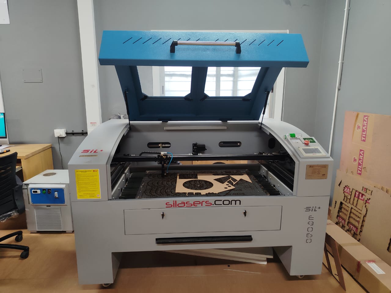
In our Nellai lab, we are using Sill Laser Cutting Machine. Sill laser cutting machines are high-precision tools used for cutting or engraving materials using a focused laser beam. The term “Sill” may refer to a specific brand or a model, but generally, these machines operate on the principles of laser cutting technology, often used in industries such as automotive, aerospace, construction, electronics, and signage.
Working Principle
A SIL E9060 laser cutting machine uses a focused laser beam to cut through materials by melting or vaporizing them. The laser beam, guided by mirrors and lenses, is directed at the workpiece, causing localized heating and melting or vaporization of the material. Assist gases, like oxygen or nitrogen, may be used to blow away the molten or vaporized material, resulting in a clean cut.
Reference Link
Sil Laser Cutting MachienMaterials Compatible with Laser Cutting
-> Wood like Plywood, MDF, and solid wood.
-> Acrylic & Plastics.
-> Leather & Fabrics
>
-> Paper & Cardboard
-> Glass & Ceramics
-> Rubber
Applications of Laser Cutting Machines
2. Signage & Engraving
3. Textile & Leather Industry
4. Architecture & Model Making
5. Personalized Products
Video Tutorial - Laser Cutter
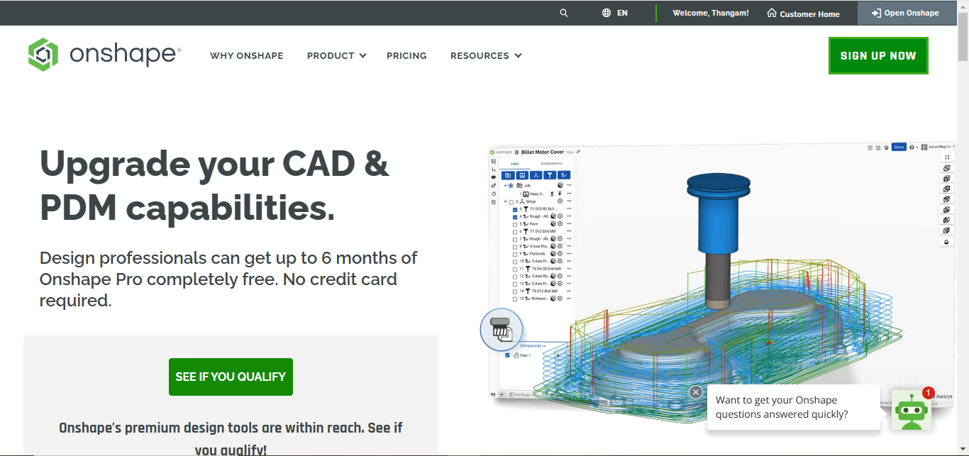
ONSHAPE
Onshape is a cloud-based CAD (Computer-Aided Design) software used for 3D modeling, product design, and engineering. Unlike traditional CAD programs, Onshape runs entirely in a web browser, allowing real-time collaboration, version control, and access from any device. It is widely used in mechanical design, prototyping, digital fabrication, and education.
Application
2D Drawings - Generate technical drawings for manufacturing.
Collaboration - Multiple users can edit designs in real-time.
Version Control - Track design history and restore previous versions.
Simulation & Analysis - Perform stress analysis and motion studies.
Integration with CAM & Laser Cutting - Export DXF/DWG files for fabrication.
Assignment
Group AssignmentIndividual Assignment
Digital Fabrication - Vinyl Cutting & Parametric Construction Kit
-> Cut something on the vinylcutter.
-> Design, lasercut, and document a parametric construction kit,
accounting for the lasercutter kerf,
which can be assembled in multiple ways,
Objective
This assignment focuses on utilizing computer-controlled cutting techniques, specifically through the use of vinyl cutters and laser cutters. The objective is to design and fabricate a parametric construction kit, considering factors such as laser cutter kerf and the ability to assemble the kit in multiple configurations. Additionally, the assignment explores incorporating non-flat elements to enhance the complexity and functionality of the design.
Vinyl Cutting
Vinyl cutting is a precise process that uses a computer-controlled cutter to cut designs, letters, or patterns from sheets of adhesive vinyl or other thin materials. It is commonly used in sign-making, custom decals, t-shirt graphics, and sticker production. The cutter operates by moving a small blade along programmed paths, cutting only the top layer of the vinyl while keeping the backing intact for easy application. Vinyl cutting is widely used in industries such as advertising, fashion, and home decor, offering a cost-effective and efficient method for creating durable and customizable designs.
Processes Involved in Using the Vinyl CutterVinyl cutting is a subtractive manufacturing process where a computer-controlled blade cuts designs from adhesive vinyl sheets. Below are the key steps involved:
1. Design Preparation -> Software: Create or import vector-based designs (e.g., SVG, DXF, AI) into vinyl-cutting software (e.g.,
LaserCut).
-> Vector Paths: Ensure all design elements are closed paths with no gaps for clean cuts.
-> Scaling: Adjust dimensions to match the intended application (e.g., stickers, decals).
-> Material Selection: Choose adhesive vinyl sheets (e.g., permanent, removable, heat-transfer vinyl) based
on the application.
-> Loading Vinyl: Place the vinyl sheet onto the cutter's sticky backing mat (if required) or feed it
directly into the machine, ensuring proper alignment.
-> Blade Depth and Pressure: Adjust settings based on vinyl thickness (e.g., 0.1-0.5 mm). Test cuts help
fine-tune these parameters.
-> Cutting Speed: Slower speeds for intricate designs; faster for simple shapes.
-> Send Design: Upload the file to the cutter via USB or software interface.
-> Cut Execution: The blade follows the vector paths precisely, cutting only the vinyl layer while leaving
the backing intact.
5. Weeding
-> Remove Excess: Use tweezers or a weeding tool to peel away unwanted vinyl ("negative space"), leaving
only the desired design.
-> Transfer Tape: Apply adhesive transfer tape over the design to lift it from the backing for precise
placement.
-> Alignment: Position the design using transfer tape, then press firmly to adhere. Peel off the tape slowly to avoid lifting the vinyl. Key Considerations
-> Kerf Compensation: Unlike laser cutting, vinyl cutters typically don’t require kerf adjustments due to
the thin material and blade precision.
-> Multi-Layer Designs: For layered colors, cut each layer separately, align, and apply sequentially.
Laser Cutting Machine
A CO2 laser cutting machine is a powerful tool used for precise cutting, engraving, and marking of various materials. It operates using a high-energy CO2 laser beam that vaporizes or melts the material to create intricate designs with high accuracy.
Design
The parametric construction kit was designed using Onshape. I defined key parameters such as material thickness, slot depth, and tab length using Onshape’s variable feature. These parameters controlled the geometry of each part, ensuring a tight and adjustable fit, especially accounting for laser kerf. By adjusting a single variable (e.g., material thickness), I could generate new sets of parts suitable for different materials without redrawing the model.
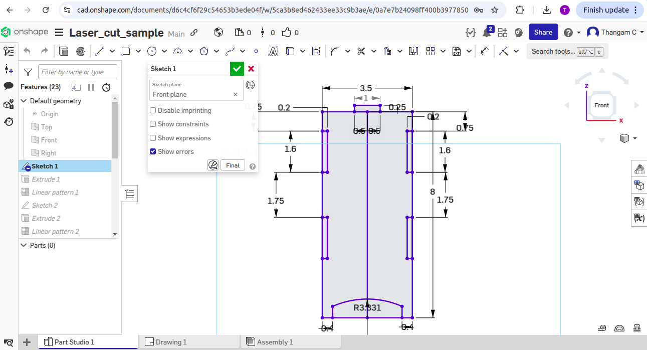
Parametric 2D Design
The design incorporates various features, including Sketch, Extrude, Linear Pattern, and Boolean operations, to ensure flexibility and adaptability. The parametric approach allows for easy modification of dimensions and features.
Step by step design procedure
-> small rectangles were added as tabs with dimensions linked to thickness(0.2 inches).
-> constraints like equal length and spacing between tabs were used.
-> Mirrorring is used to set the tabs about a centerline for symmetry.
-> A recess and a tab were added for the lid, all dimensioned parametrically.
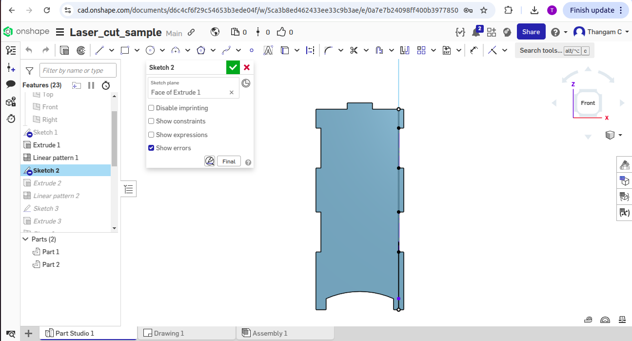
-> Extrudes the 2D sketch to create the side piece of the lamp.
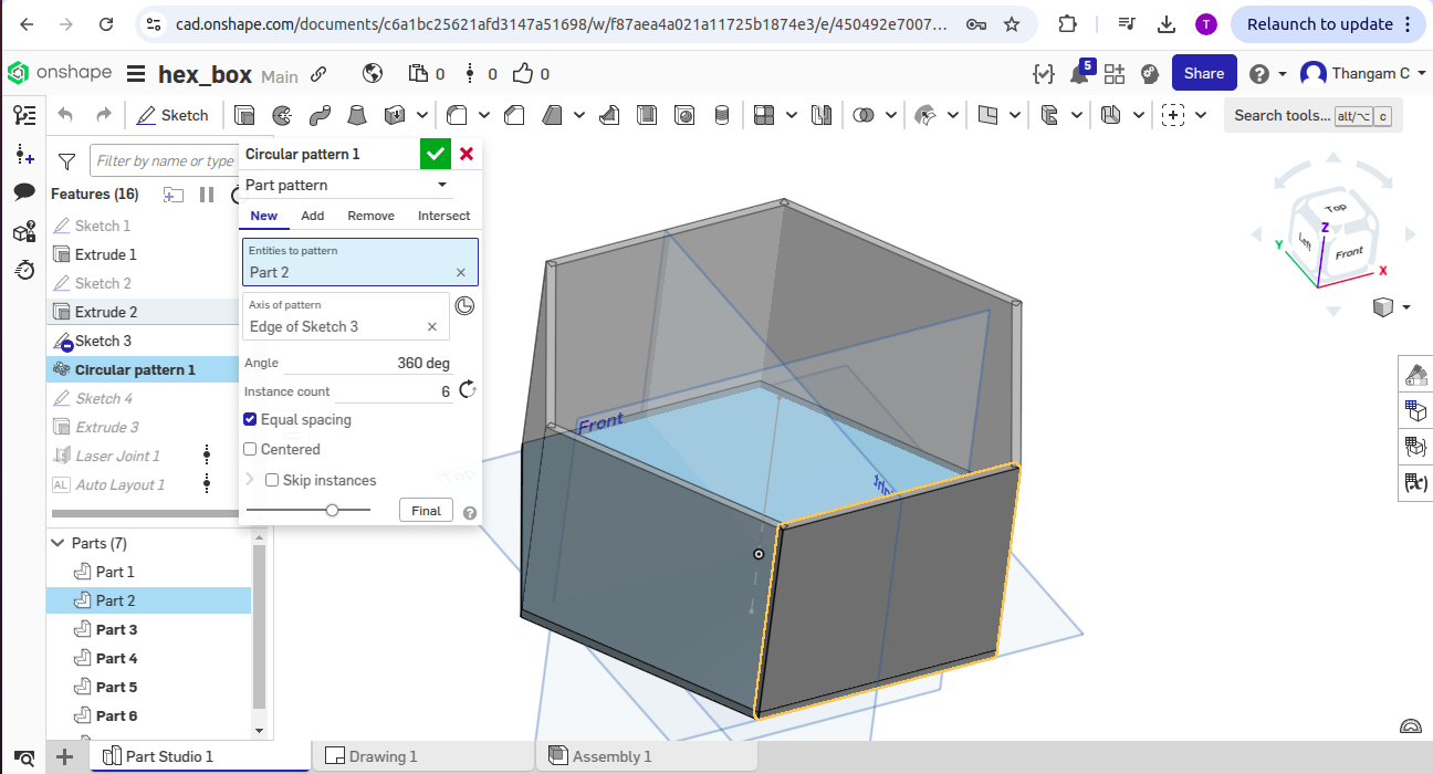
-> Copies and patterns the side piece for the other parts of the box was done by using mirroring/patterning features.
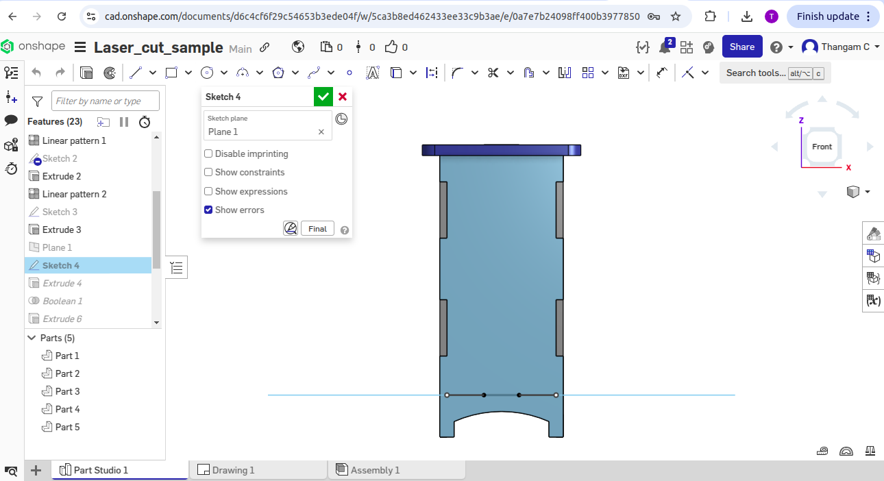
-> A rectangle on the top surface was created to outline the lid's boundary as a guide.
-> An offset distance was set (0.5 inches) to define how much the lid sticks out beyond the base.
-> A fillet feature was applied (rounded corner) to the offset rectangle corners for a smooth edge.
-> Extrudes the 2D sketch to add thickness and form the lid piece.
-> A new offset plane was created below the top surface to sketch the bottom piece at the correct depth(0.118inches).
-> The bottom piece on the new plane was drawn by copying key corners and tab spots from existing parts.
-> The bottom piece was made slightly smaller than the tabs to ensure it fits inside the box.
-> Extrudes the bottom piece upwards to give it thickness.
-> A boolean subtract feature was used to cut holes or remove overlapping parts for proper fitting.
-> Now all the the assembly parts are checked for fittness by hiding construction planes and showing all parts together.
Dimensions Used to design this sketch
-> Width and Depth: 3.5 inches and 0.118 inches.
-> Tab height: Height divided by 5 (which is 8 inches / 5 = 1.6 inches).
-> Tab spacing from top edge: 0.75 inches.
-> Distance between tabs: 1.75 inches (approximate, made up by the designer).
-> Tab thickness: 0.2 inches.
-> Top tab size: 0.5 inches.
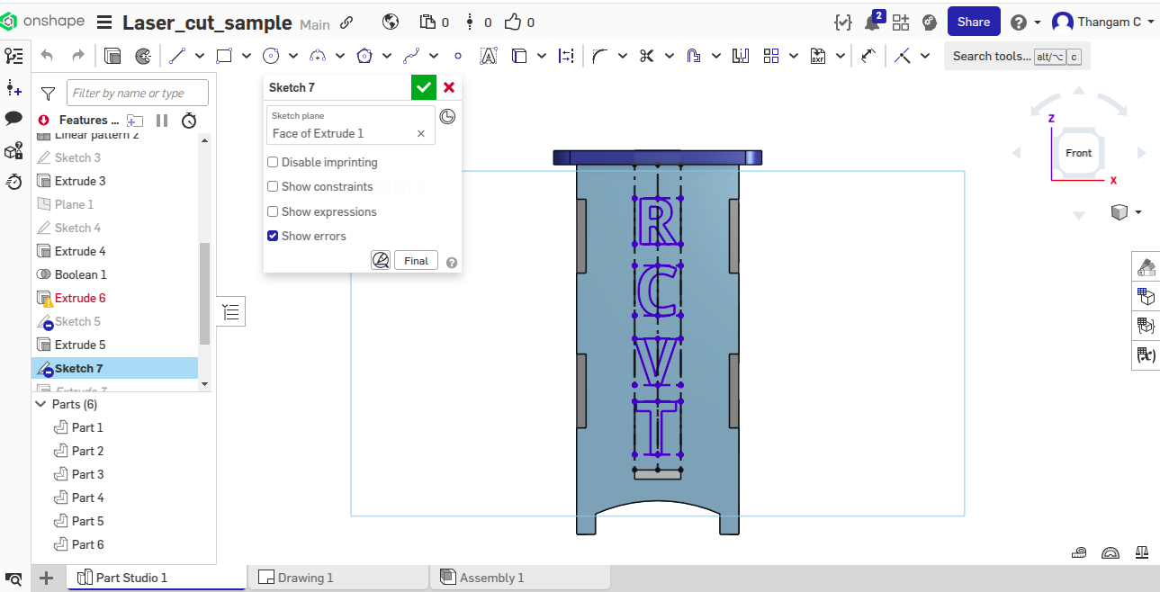
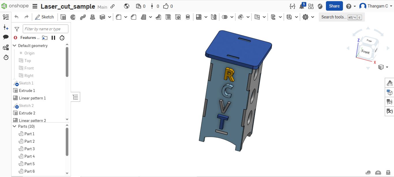
3D View screenshots
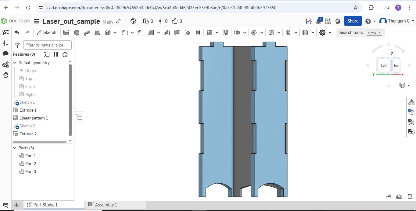
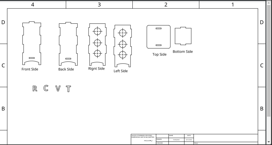
2D View
Download Original Design Files
Click on the links below to download the original design files:
Design Preparation
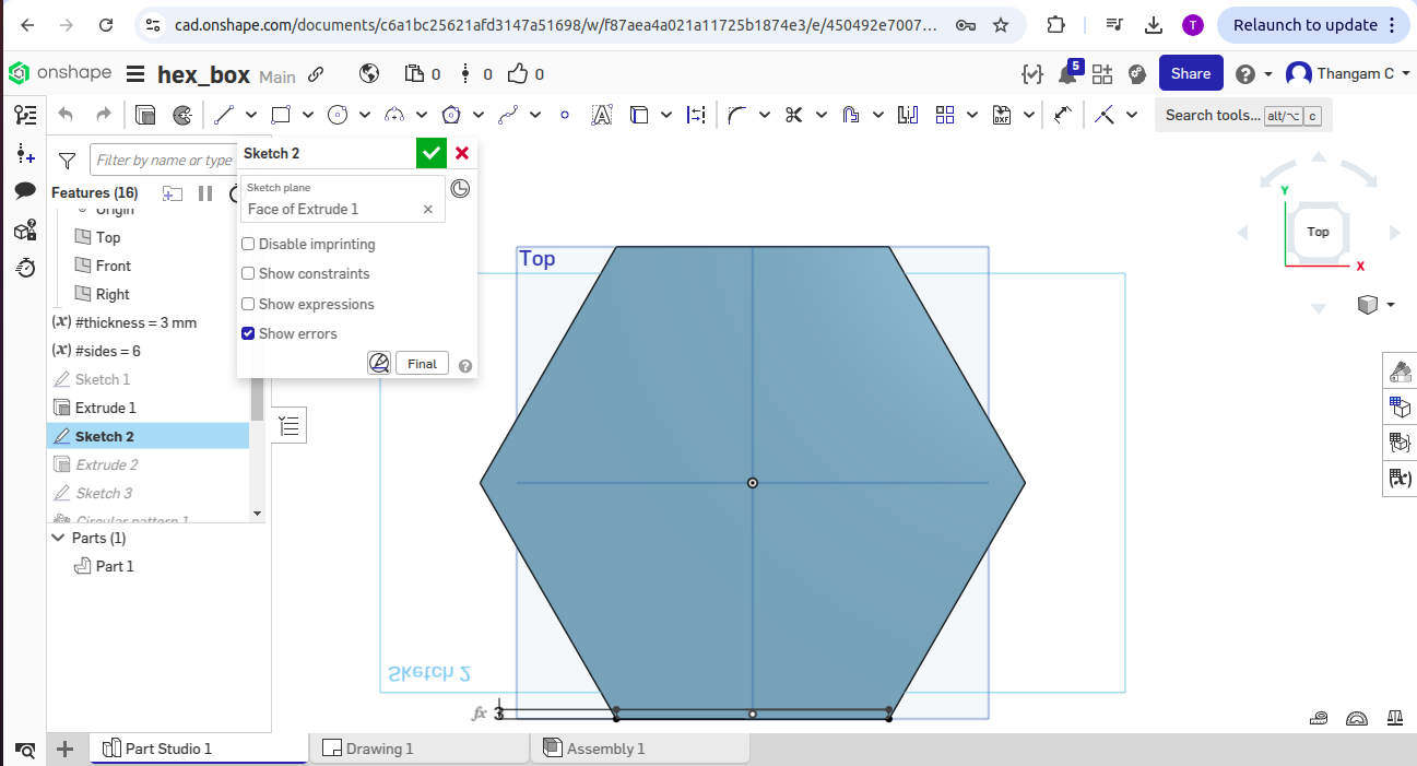
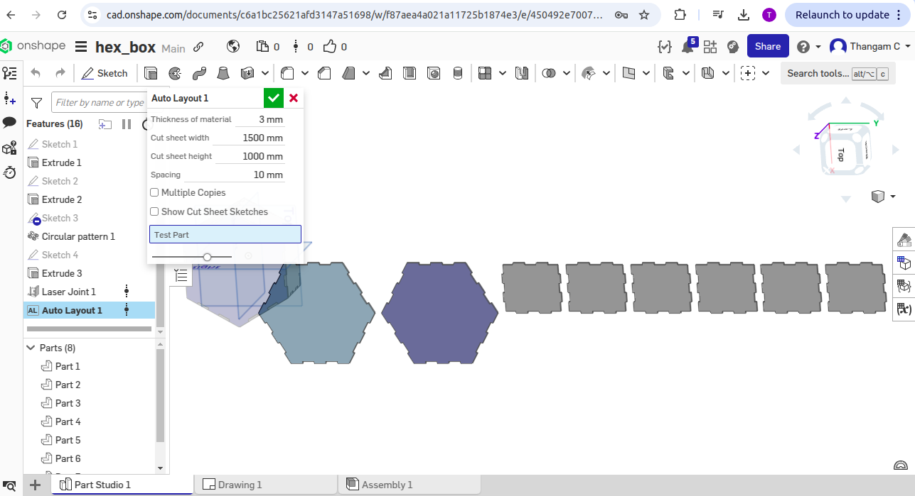
I designed a lamp structure and a hexagon box using Onshape, a cloud-based 3D CAD modeling platform. After completing the designs, I exported the individual parts in both PDF and DXF file formats—commonly used for laser cutting because they preserve precise 2D vector outlines necessary for accurate cutting and engraving.
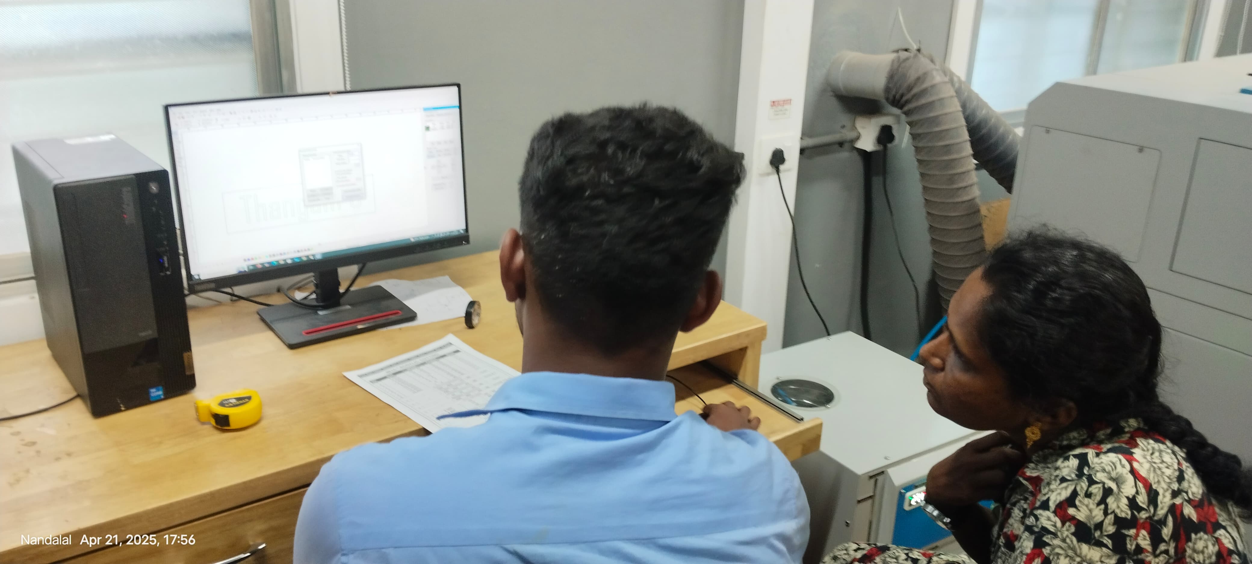
These files were then imported into the laser cutting software (such as RDWorks or LightBurn), which serves as the interface between the design and the laser cutting machine. This software allows users to define which elements of the design should be cut and which should be engraved. Different colors or layers are used to assign cutting and engraving operations, and it provides the tools to adjust settings like power, speed, number of passes, and focus height.
Detailed Steps-> Imported DXF/PDF files into the laser cutting software.
-> Assigned cut paths for outer shapes and engraving paths for text and patterns.
-> Configured laser parameters:
         Cutting Power:  ~80% (suitable for 3mm MDF)


         Cutting Speed: ~10-15 mm/s


         Engraving Power/Speed: ~40% power and 200 mm/s


         Focus: Calibrated using the focus tool for clean cuts
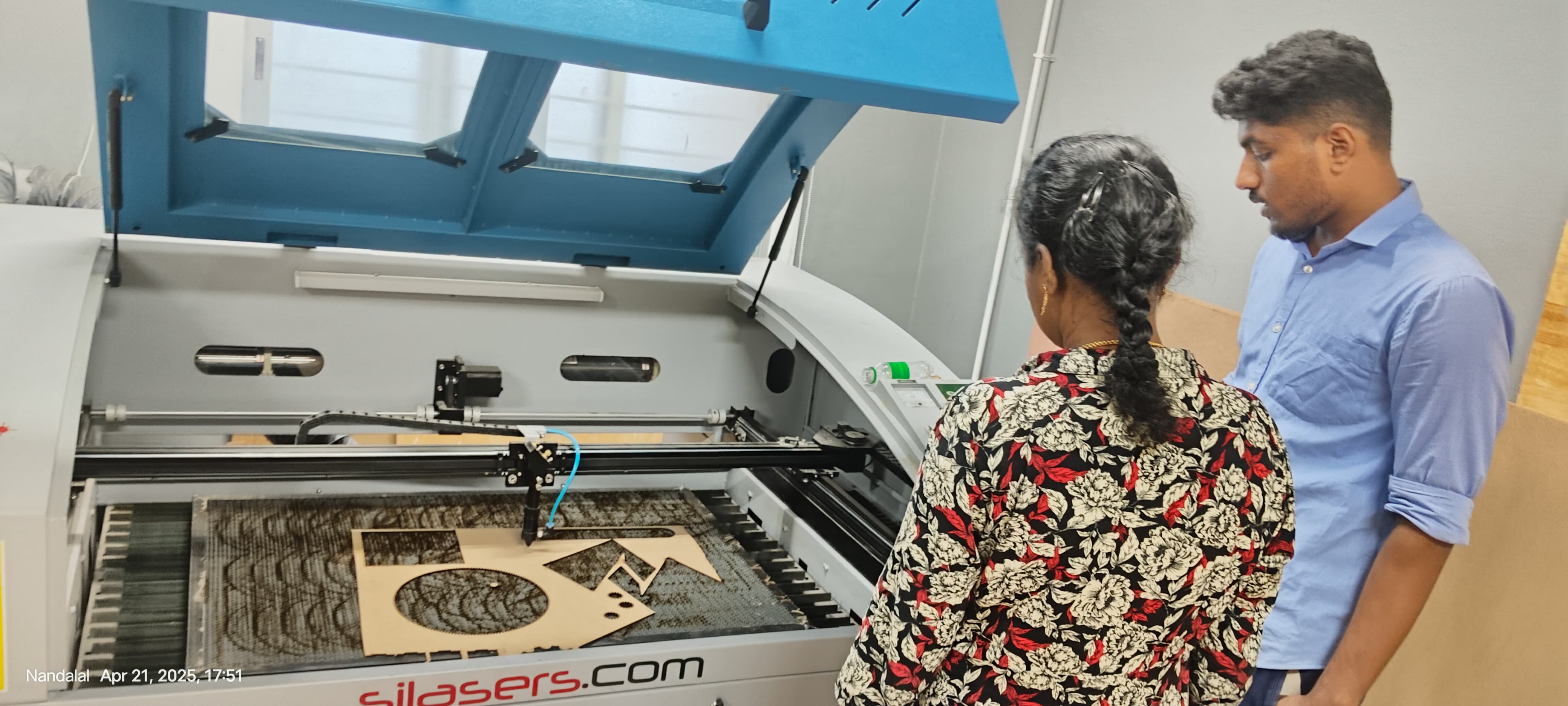
Once the setup was verified, I sent the file to the SIL E9060 laser cutter. The MDF sheet was properly placed and secured, and the exhaust system was activated for safety. The machine completed the cutting and engraving tasks without error.
While printing the lamp structure, I encountered some issues. The original lamp design had a thickness of only 0.2 mm, while the MDF sheets available in our lab were 3 mm thick. Additionally, the overall dimensions of the lamp parts were too small, resulting in a very tiny printed object that was not practical for use.
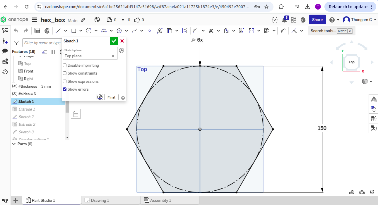
To address this, I redesigned a new object-a hexagon box-with standard and practical dimensions suitable for 3mm MDF. After re-exporting and preparing the new file in the laser cutting software, the hexagon box was successfully printed with clean cuts and proper fitting parts.
This process helped me understand the importance of matching design dimensions with material specifications and using the correct software settings to achieve accurate and clean results.
Hero shots for Hexagon Box
Download Original Design Files
Click on the links below to download the original design files: