- Individual Assignment
- Design and document the system integration for your final project
Manuel Ayala-Chauvin
Institution: Fablab - Universidad Tecnológica Indoamérica
Year: 2025
Manuel Ayala-Chauvin
Institution: Fablab - Universidad Tecnológica Indoamérica
Year: 2025
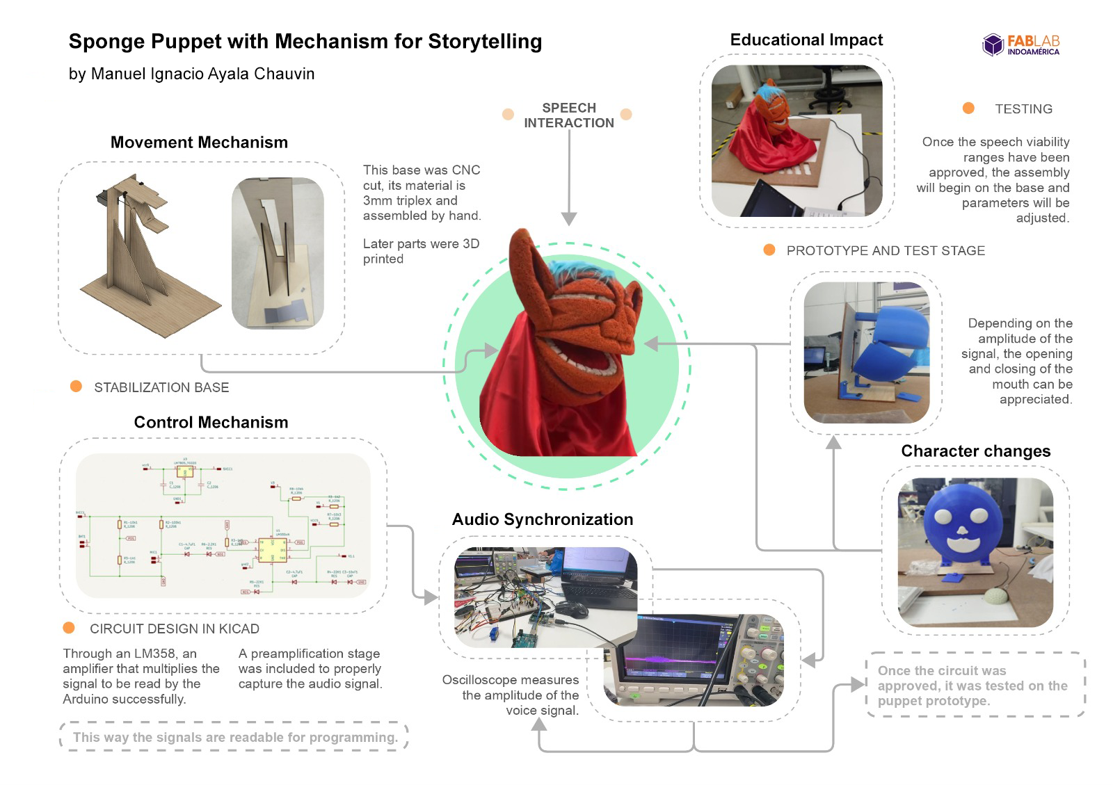
The final project, "Puppet of the 21st Century", is an expressive storytelling puppet that uses mechanical articulation, audio synchronization, and character modularity to enhance educational storytelling. The puppet is designed to interact with children in an engaging and dynamic way by syncing its mouth and face movements with audio narration, offering visual expressiveness and educational support through a mobile application.
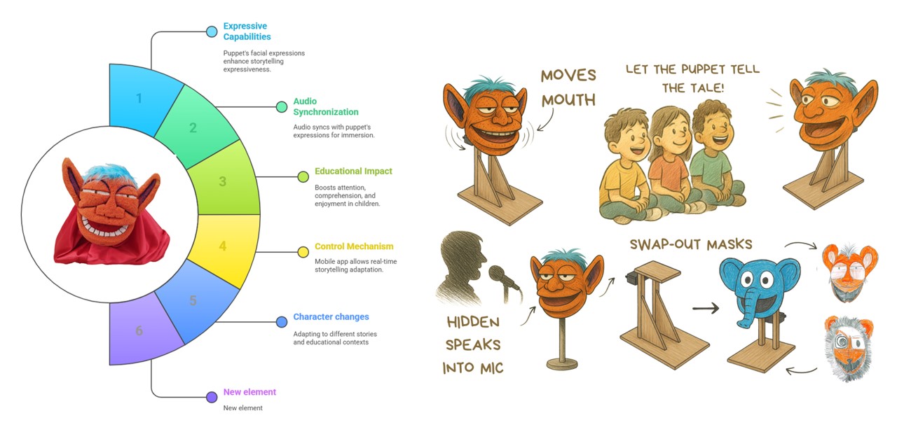
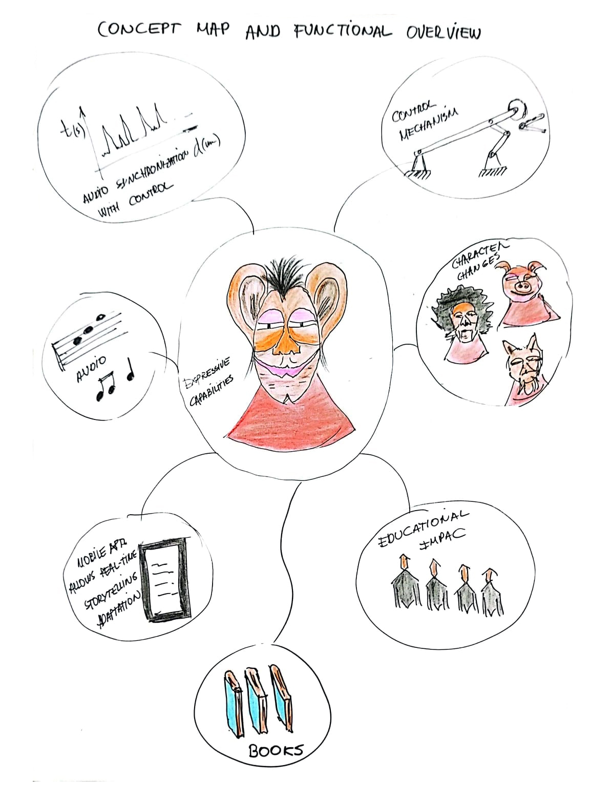
This concept map shows the major functional components:
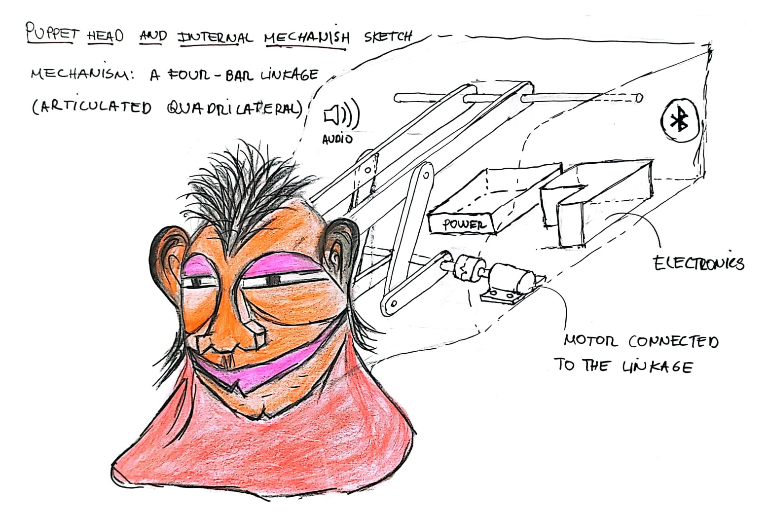
The puppet integrates a four-bar linkage mechanism connected to a servo motor. The mechanism is enclosed within a wooden chassis and interacts with a power supply, Bluetooth module, and audio trigger for movement.
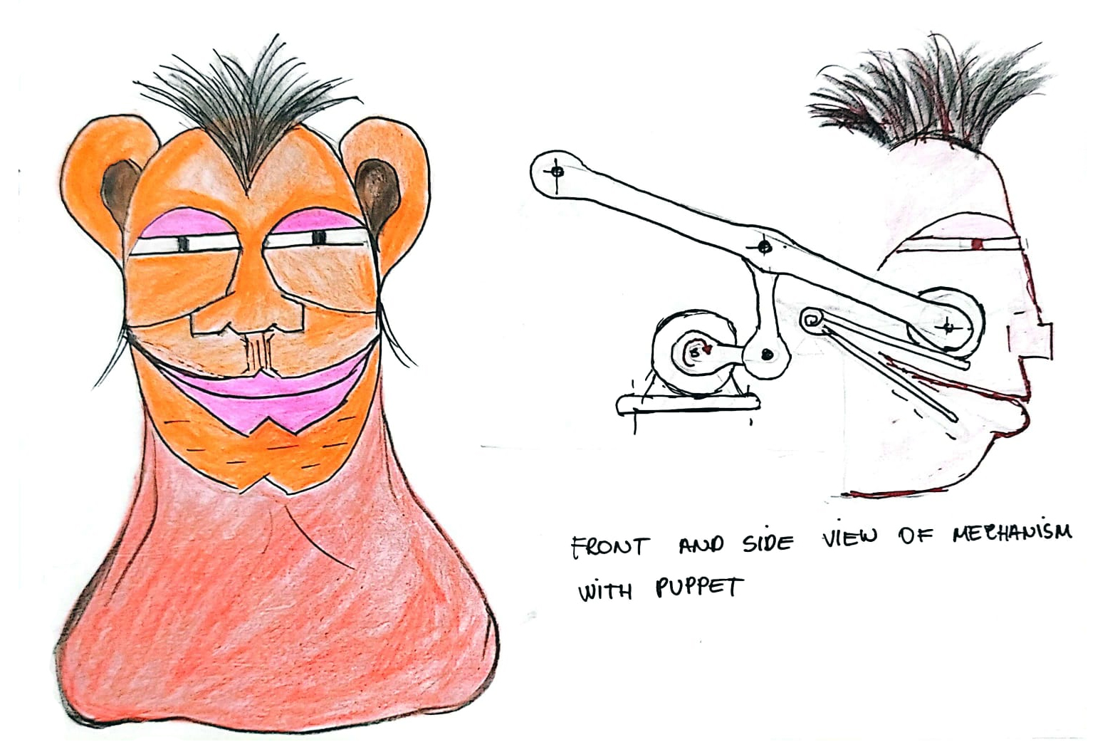
The image shows:
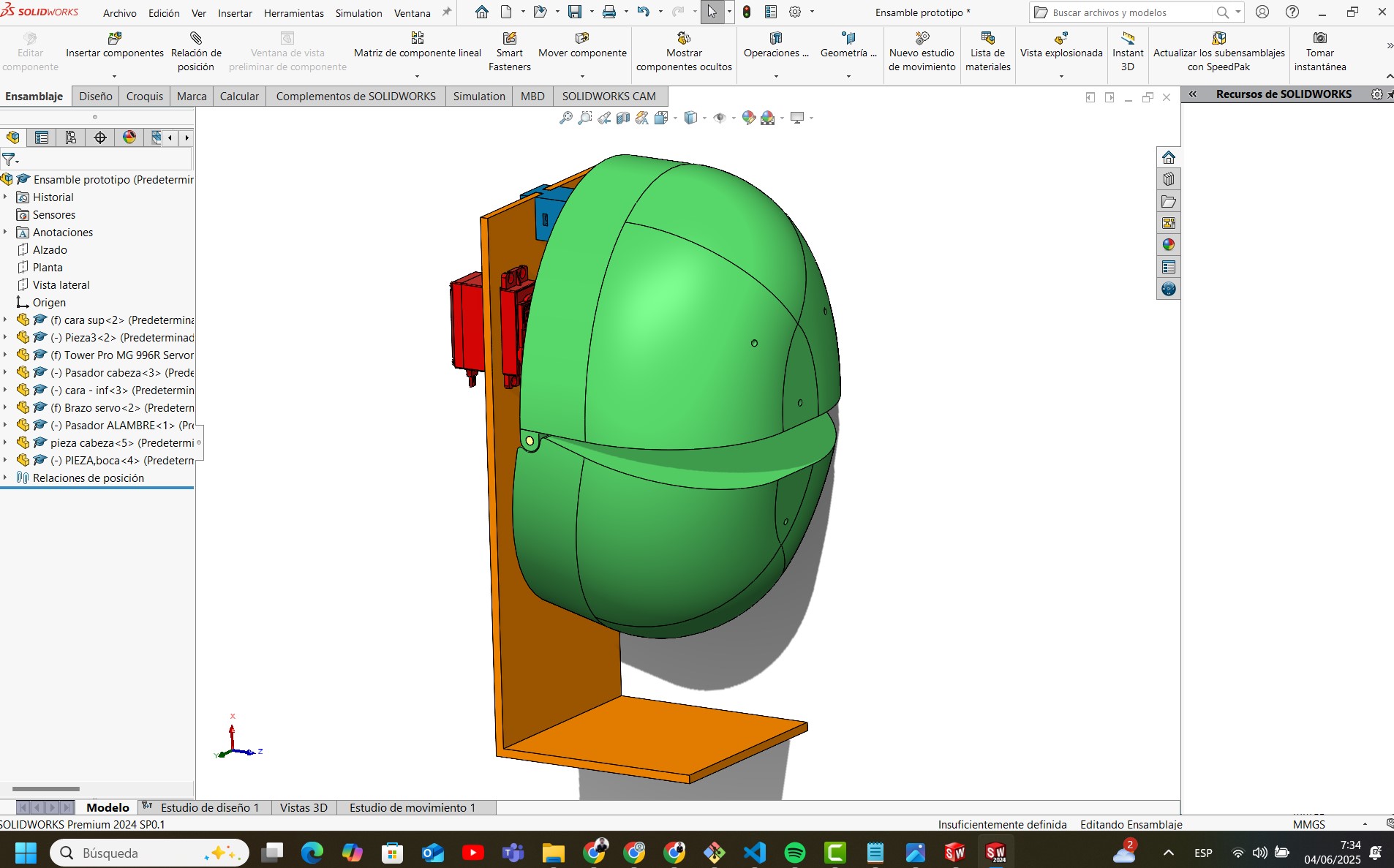
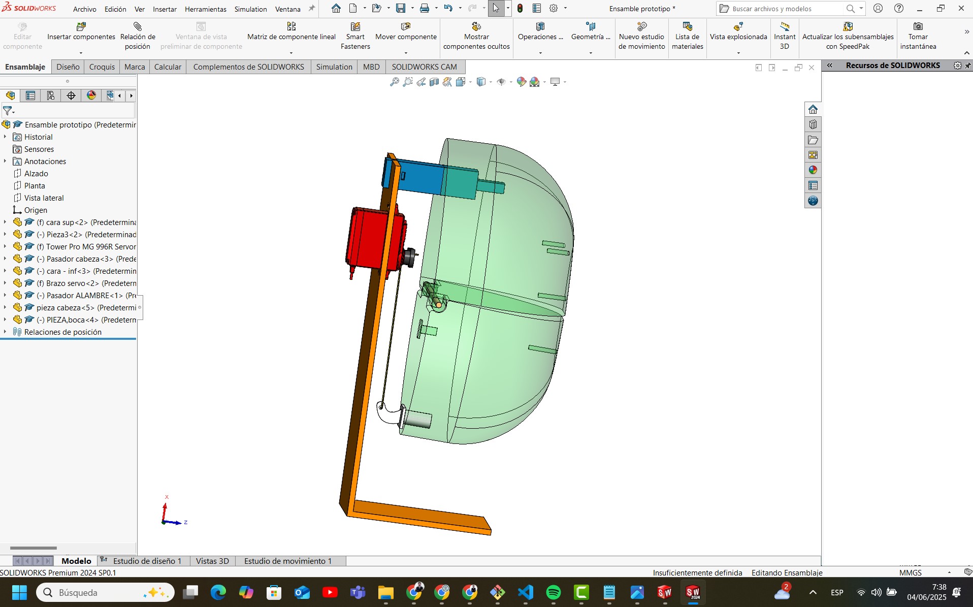
This section documents the conceptual mechanical design of the puppet's head movement system. The structure was modeled in SolidWorks and integrates a physical support, servo-driven mechanisms, and a rotating jaw.
The orange L-shaped frame provides a stable base to mount all components. It ensures rigidity and alignment between the servos and the puppet's head. All parts are designed for easy assembly using bolts or press-fit systems.
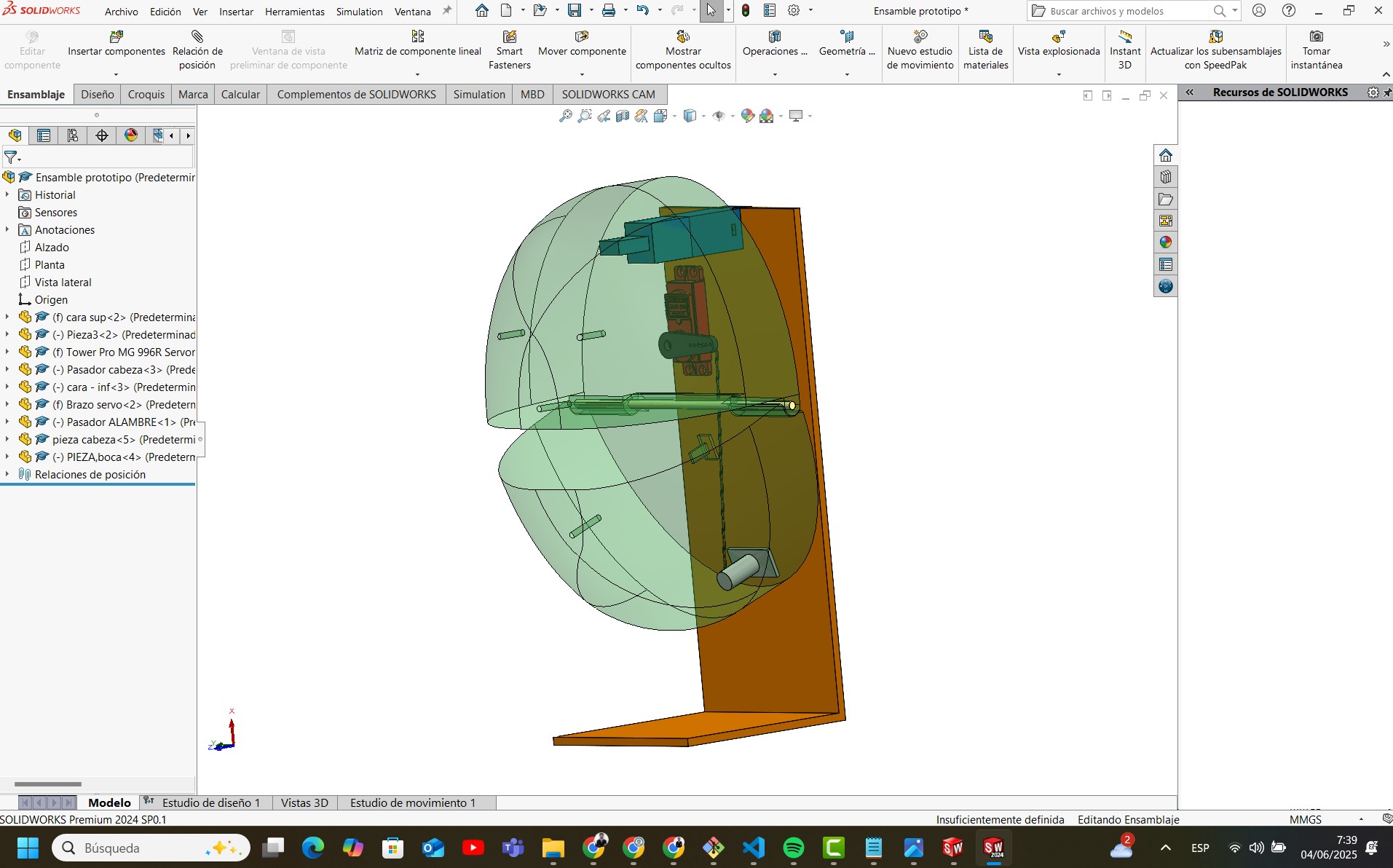
In the following view, the puppet’s head is shown semi-transparent, revealing the internal servo motors, pivots, and transmission rods that control jaw movement. The main servo (MG996R) is mounted on the back and pushes a printed lever connected to the lower jaw.
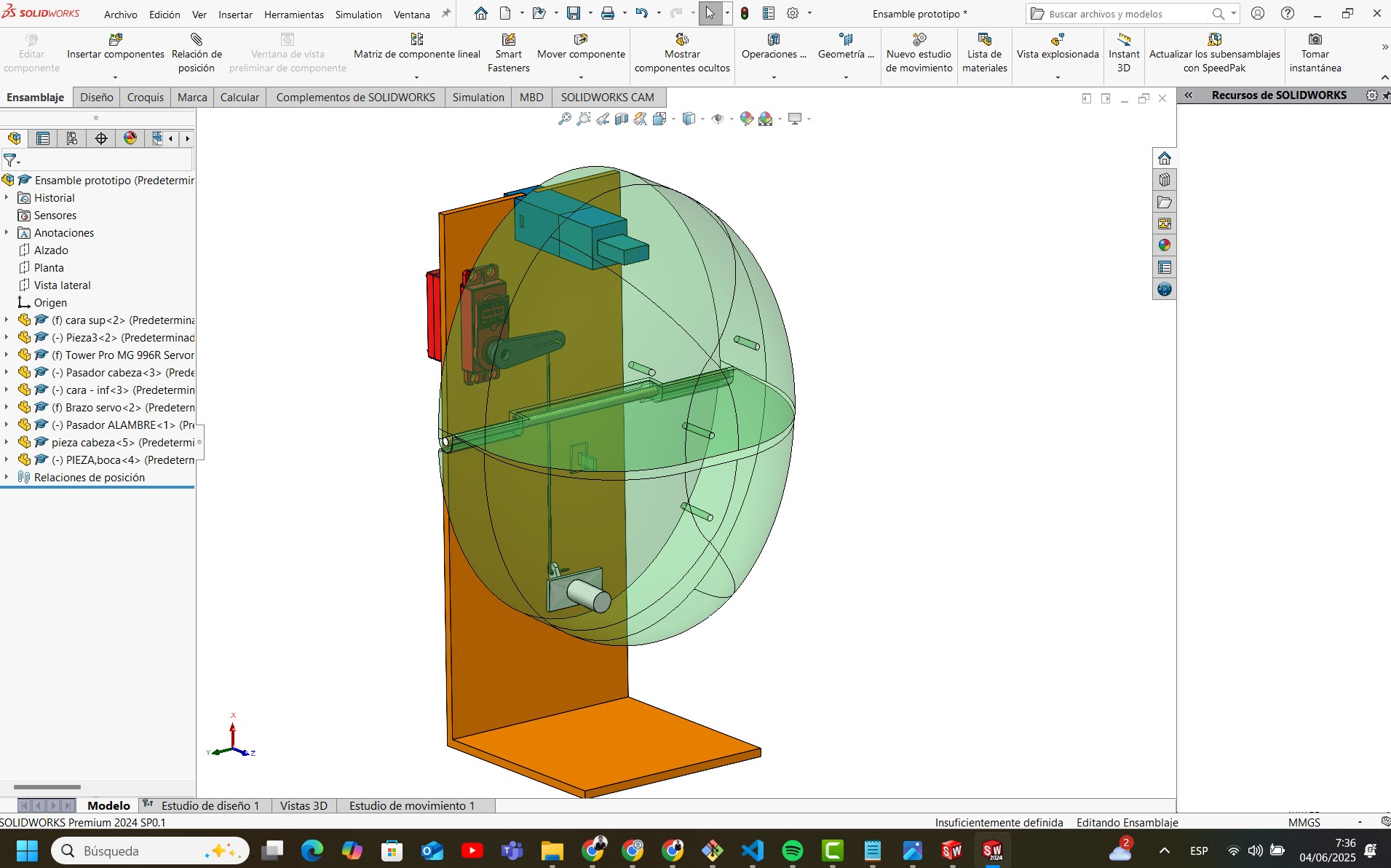
The side perspective shows the angular motion path of the jaw. The linkage system was dimensioned to allow natural-looking mouth movement with minimal force.
The next view shows how each part is kinematically constrained. The arm of the servo rotates and transmits the force through a direct mechanical linkage. No springs or elastic return mechanisms are used; instead, passive motion is governed by the servo’s torque and calibrated endpoints.
The video below shows the movement of the assembled prototype. You can observe the servo moving the jaw using the mechanical transmission inside the puppet's head.
The mechanical subsystem is a compact, functional unit that allows natural articulation of the puppet’s jaw using servo actuation. Its integration with the structural frame and 3D-printed elements enables fast prototyping and easy testing of expressive movements. This design will be used in combination with textile and electronic subsystems as part of the final puppet system.
The electronic system developed for the puppet enables voice-activated control of movement using a microphone, an analog amplifier, and a custom microcontroller board. This subsystem captures sound signals, amplifies them, and processes the signal to trigger movements in the mechanical subsystem.
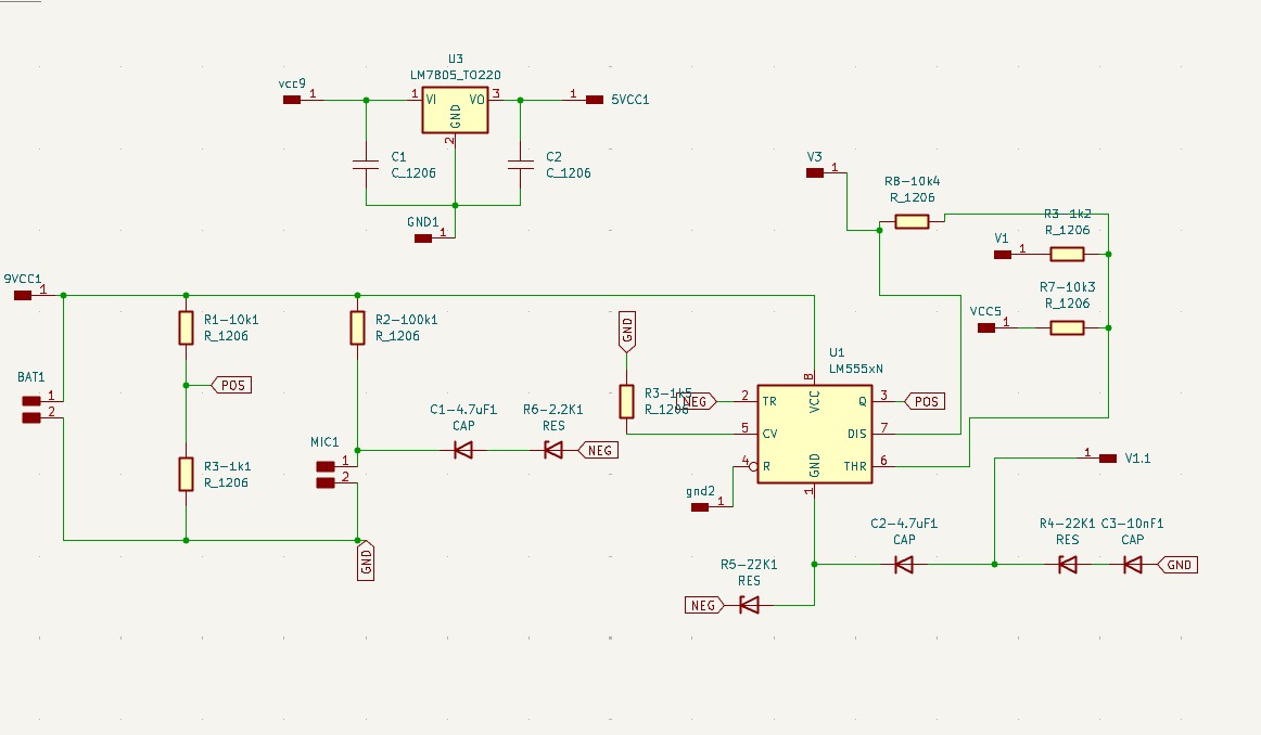
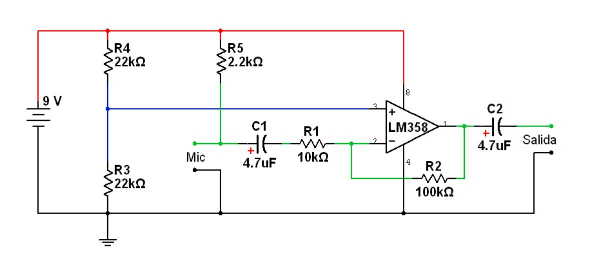
The following schematic shows the preamplifier circuit based on the LM358 operational amplifier. It receives the audio signal from a microphone and applies a gain defined by resistor R2. Capacitor C1 acts as a coupling stage, while R3 and R4 form a voltage divider to bias the non-inverting input. The output is DC-decoupled by C2 and sent to the microcontroller for processing.
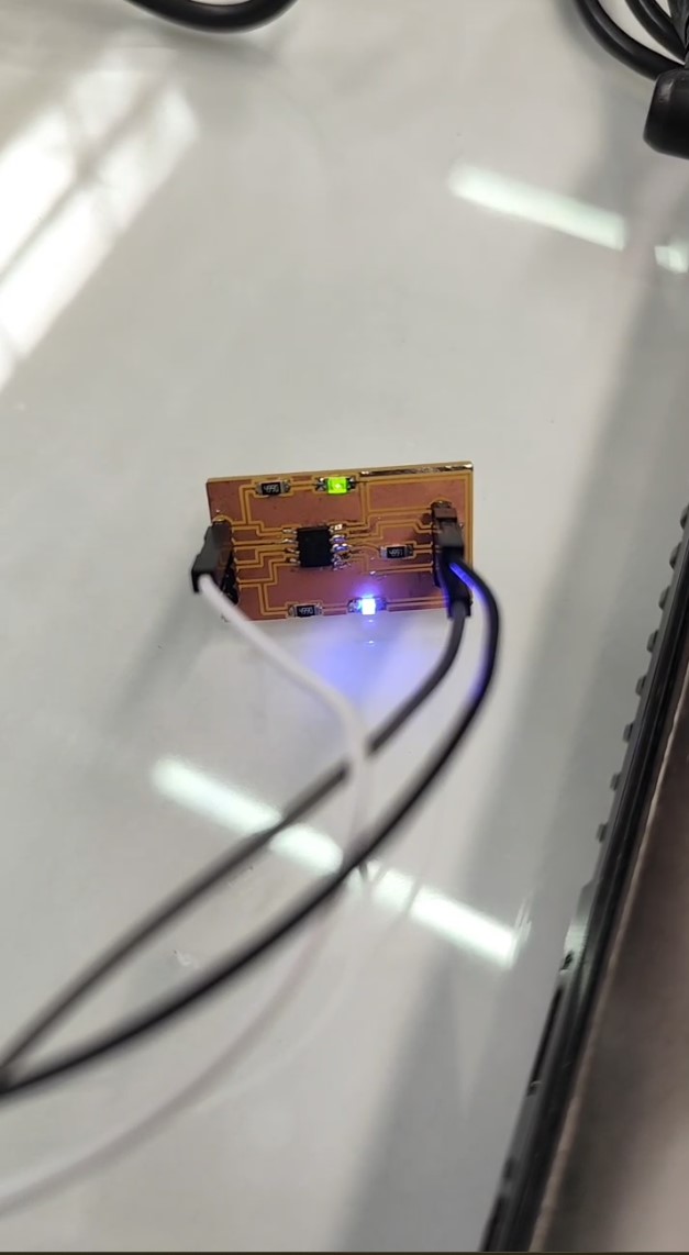
The amplifier output feeds into a PCB designed to detect audio peaks. This board, shown below, was milled and soldered in-house. It uses an ATtiny microcontroller programmed to read analog signals and produce a PWM output when sound intensity exceeds a threshold. The PWM signal drives a servo motor responsible for animating the puppet’s jaw.
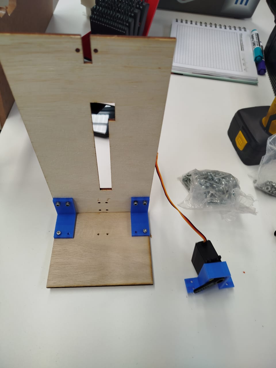
The next image shows the prototype setup with the servo mounted to a laser-cut wooden base. The system receives the PWM signal generated by the microcontroller and translates it into a jaw movement. The linkage is calibrated to respond proportionally to sound intensity.

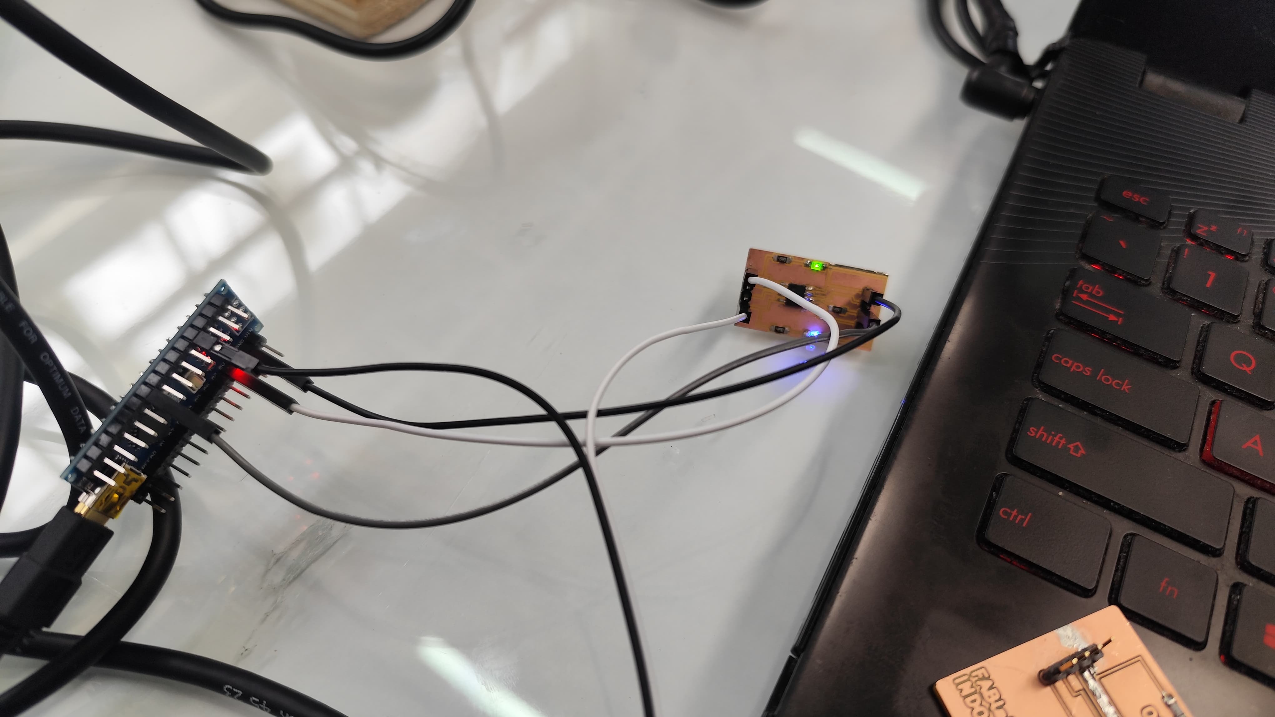
In the videos below, the entire system is demonstrated. A sound (such as a voice or a clap) is captured by the microphone, amplified by the LM358 circuit, and processed by the custom PCB. This results in a corresponding motion from the servo, visually demonstrating the mouth opening of the puppet.
The following code allows a puppet to move its mouth in response to ambient
sound.
It reads analog values from a microphone connected to pin A0
and
controls a servo motor on pin 9 based on the detected volume
level.
#include
Servo miServo;
int pinServo = 9;
int soundPin = A0;
float data_ant=0;
float data=0;
float data_Act=0;
float k;


const int micPin = A0;
float env = 0.0;
const float alpha = 0.1; // Constante de suavizado
// the setup routine runs once when you press reset:
void setup() {
  // initialize serial communication at 19000 bits per second:
  Serial.begin(19200);
  miServo.attach(pinServo);
}

// the loop routine runs over and over again forever:
void loop() {
int raw = analogRead(micPin);
  int centered = raw - 570;
  float absSignal = abs(centered);
  env = alpha * absSignal + (1 - alpha) * env;

Serial.print("Envolvente: ");
Serial.println(10*env);
miServo.write(env);
delayMicroseconds(100);
}
A0 is
used to
read voltage variations from an electret microphone, which represents
incoming
sound signals.
env = alpha * abs(centered) + (1 - alpha) * env;miServo.write(env).
This moves the servo arm in proportion to sound intensity, producing a
mouth-like motion in sync with speech or claps.
This script forms the core of the puppet's interactive behavior. By converting real-time audio into mechanical motion, it enables the puppet to mimic human-like mouth movements. The result is a reactive, expressive character that appears to "talk" based on environmental sound cues.
This electronic subsystem enables interactive control of the puppet using environmental audio. The analog front-end (amplifier) and digital signal detection circuit were designed, tested, and integrated with the mechanical components. This modular design allows future improvements such as distinguishing between voice types, intensities, or using wireless control inputs.
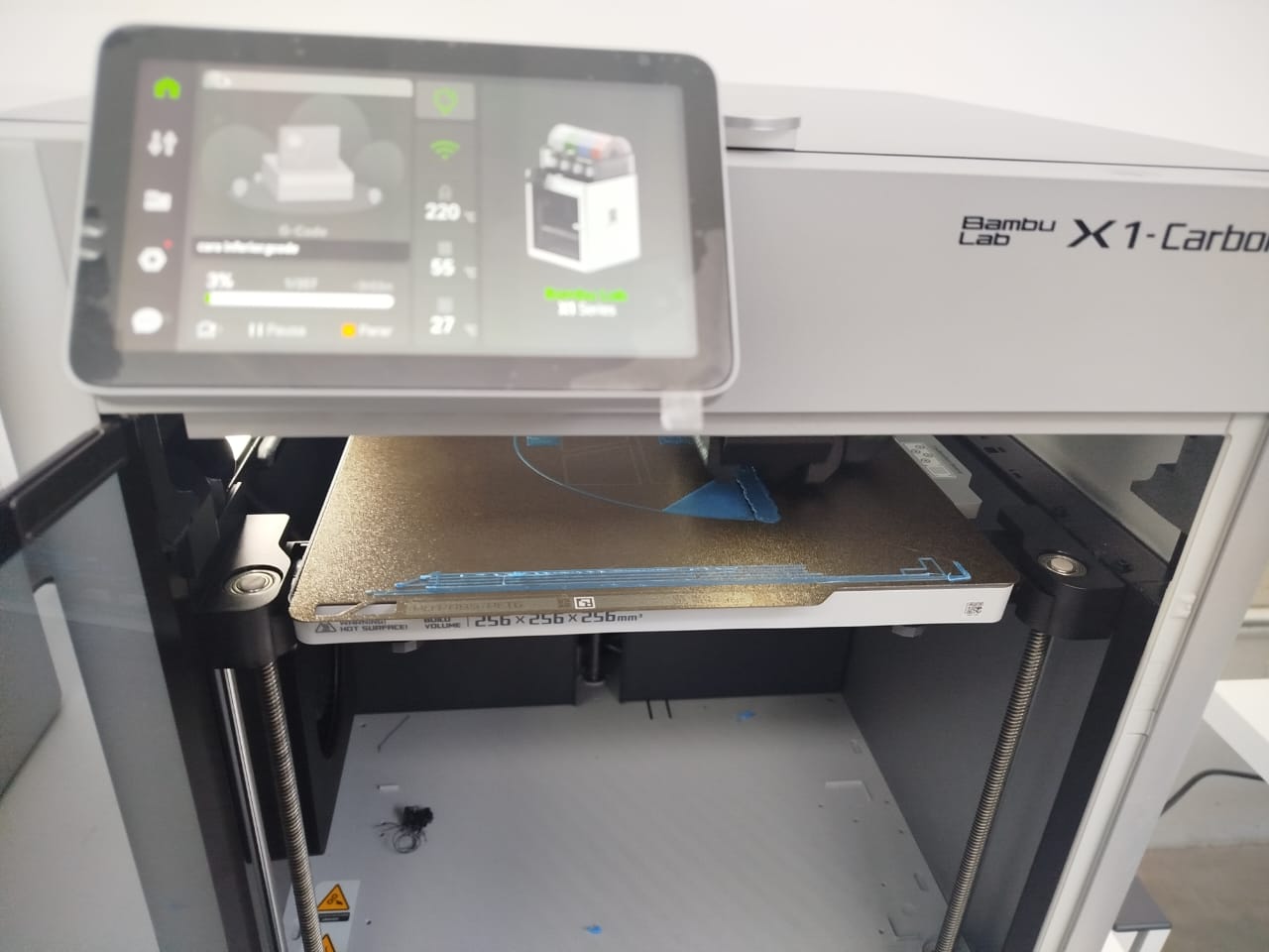
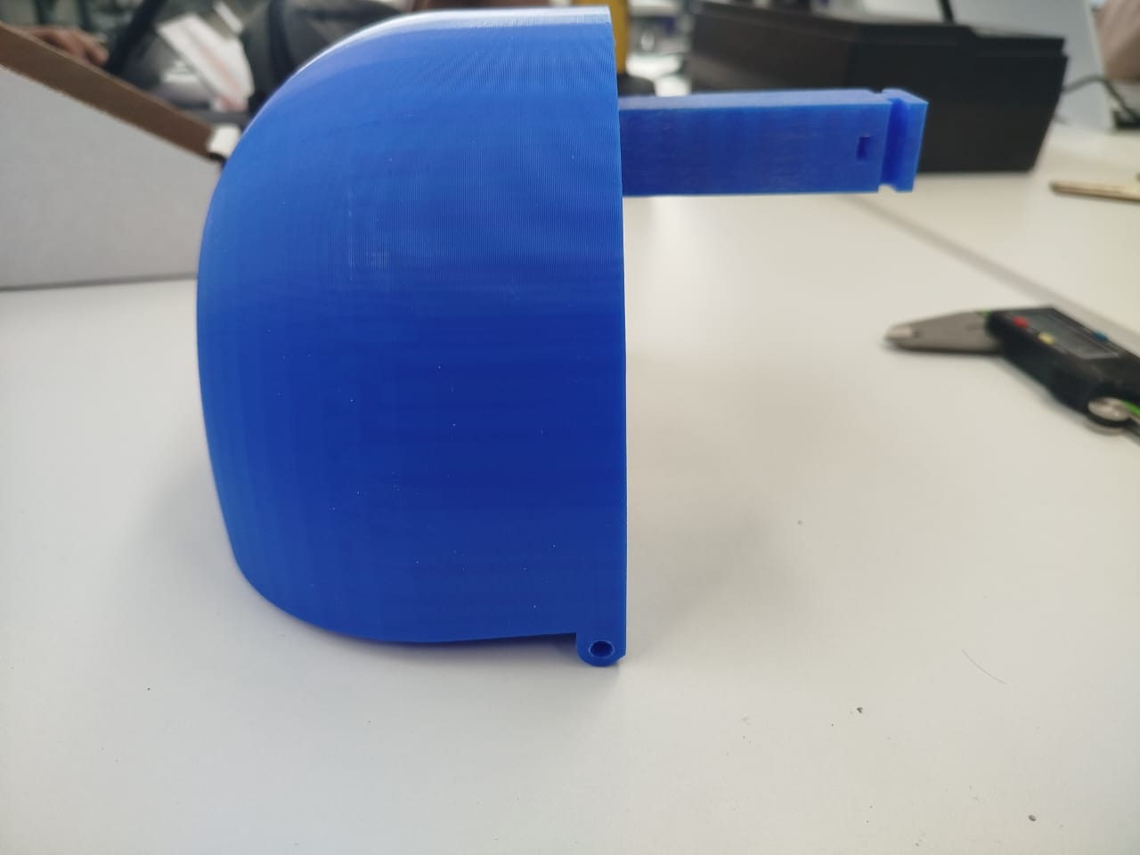
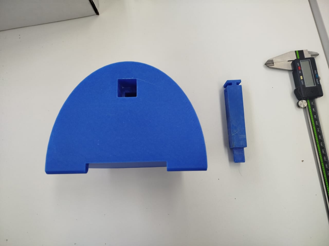
Parts printed with Bambu Lab X1-Carbon, designed to be lightweight and structurally precise for mouth motion.
These images show the minimum viable prototype (MVP) fully assembled. The jaw mechanism is tested and reacts to control signals through the servo motor.
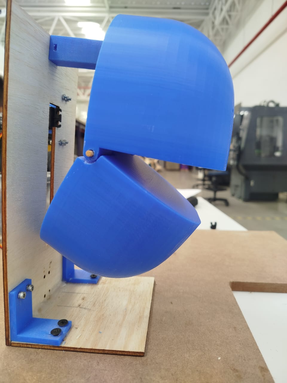
The final prototype is a fully functional interactive puppet capable of responding to environmental sounds such as speech or claps. The system integrates 3D-printed mechanical parts, a voice-activated control circuit, and a programmed microcontroller that drives the jaw movement through a servo motor.
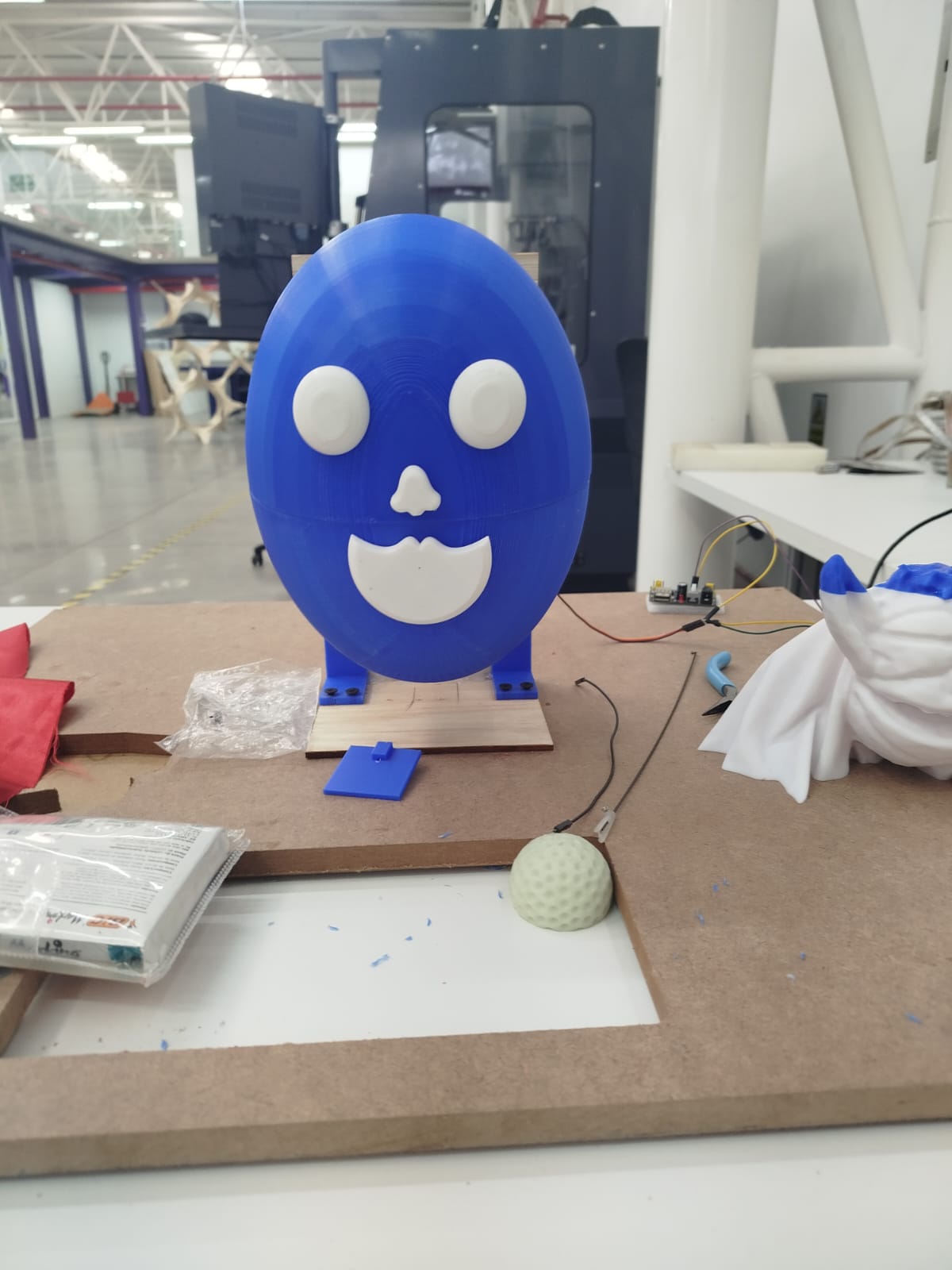
The images below show the puppet in its final assembled form. The head is composed of two 3D-printed hemispheres, where the lower section acts as a movable jaw. It is mounted on a wooden support structure that holds the servo in place.
A playful facial expression was added using white 3D-printed eyes and mouth parts, giving the puppet a more friendly and expressive appearance. The face was designed to align precisely with the moving jaw for a natural animation.
Below is a video showing the puppet in operation. When a sound is detected by the microphone, the amplifier circuit processes the signal, the microcontroller calculates the envelope, and the servo responds by opening the puppet’s mouth. This real-time interaction gives the appearance that the puppet is talking or reacting to its environment.
The result is a working electromechanical puppet that responds to sound stimuli, demonstrating successful integration of mechanical design, electronics, and embedded programming. The system is modular and extensible, allowing further development such as speech synthesis, animation synchronization, or interaction with mobile apps.
The interactive puppet is now in its final integration phase. The mechanical and electronic systems are fully functional, and the final structural pieces have been assembled. At this stage, the project is focused on installing the final control boards, polishing cosmetic finishes, and validating the overall system performance for presentation and deployment.
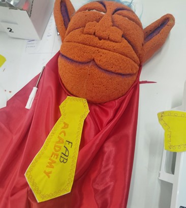
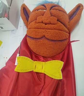
The puppet’s visual details were finished by hand, including mouth painting, ear shaping, and the integration of expressive facial lines. The red cape complements the overall design, creating a coherent theatrical appearance.

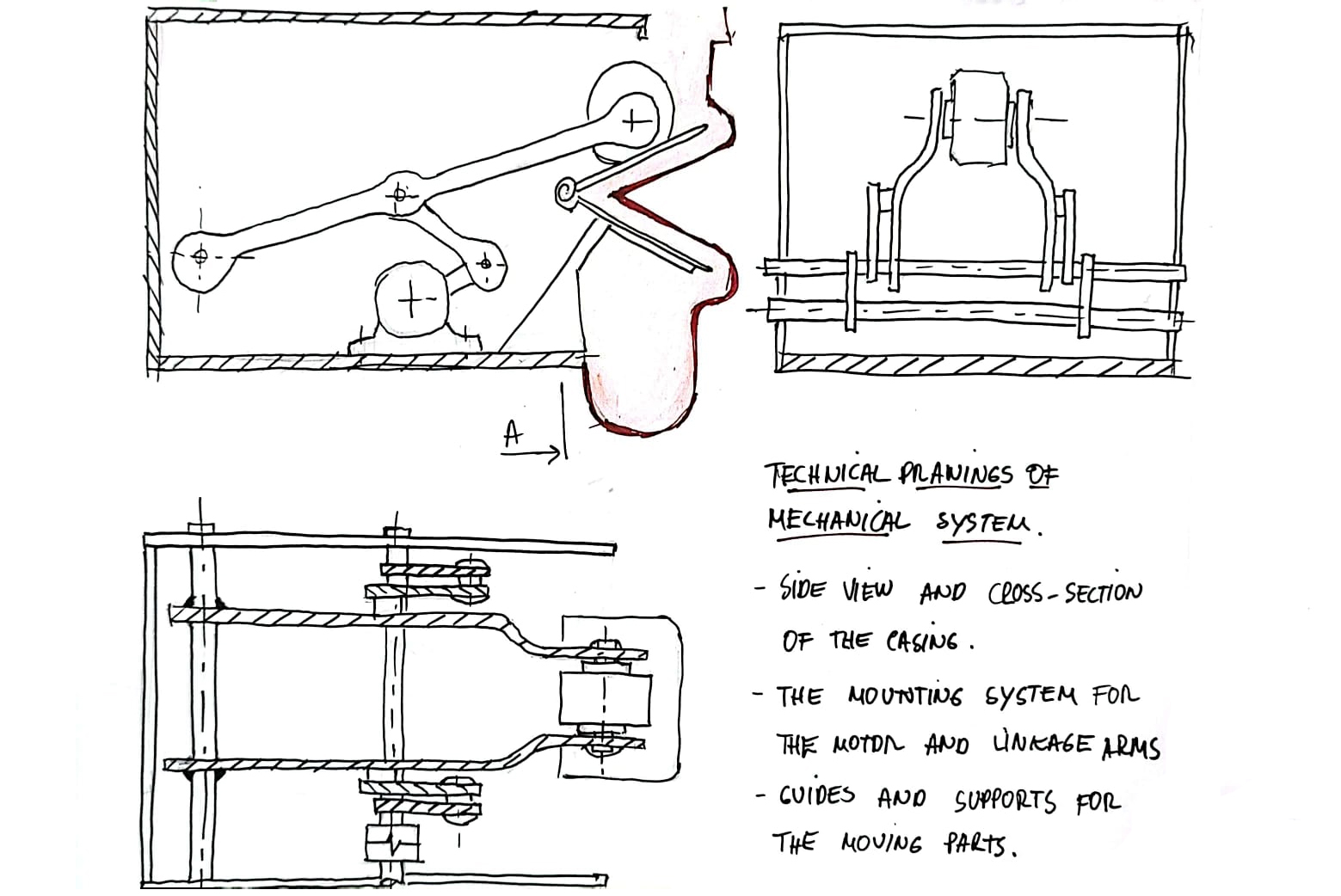
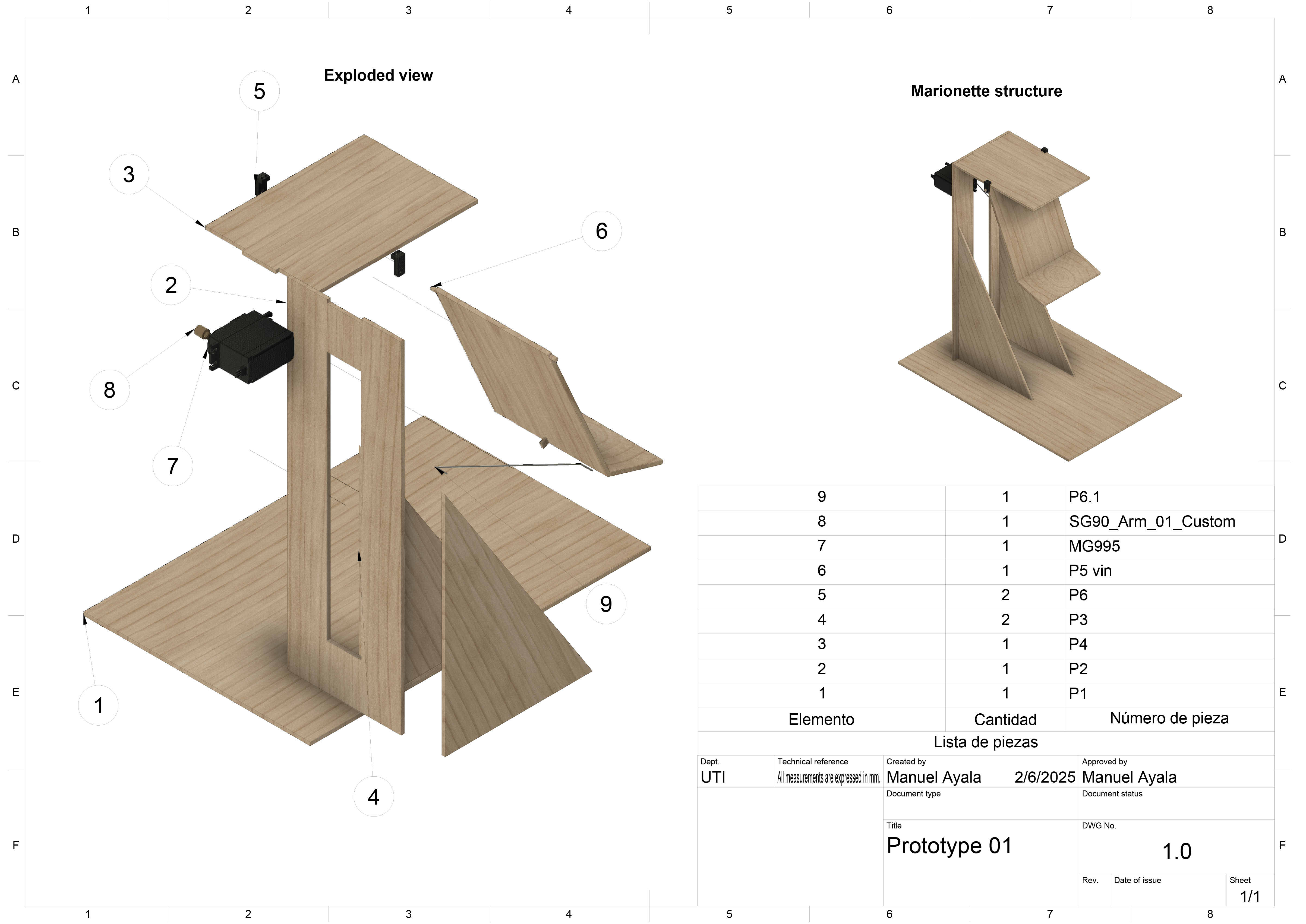
The base structure was developed with interlocking wooden panels. Below is a technical exploded view that details the arrangement and quantity of each piece, servo placement, and anchoring zones. This helps ensure reproducibility and maintainability.
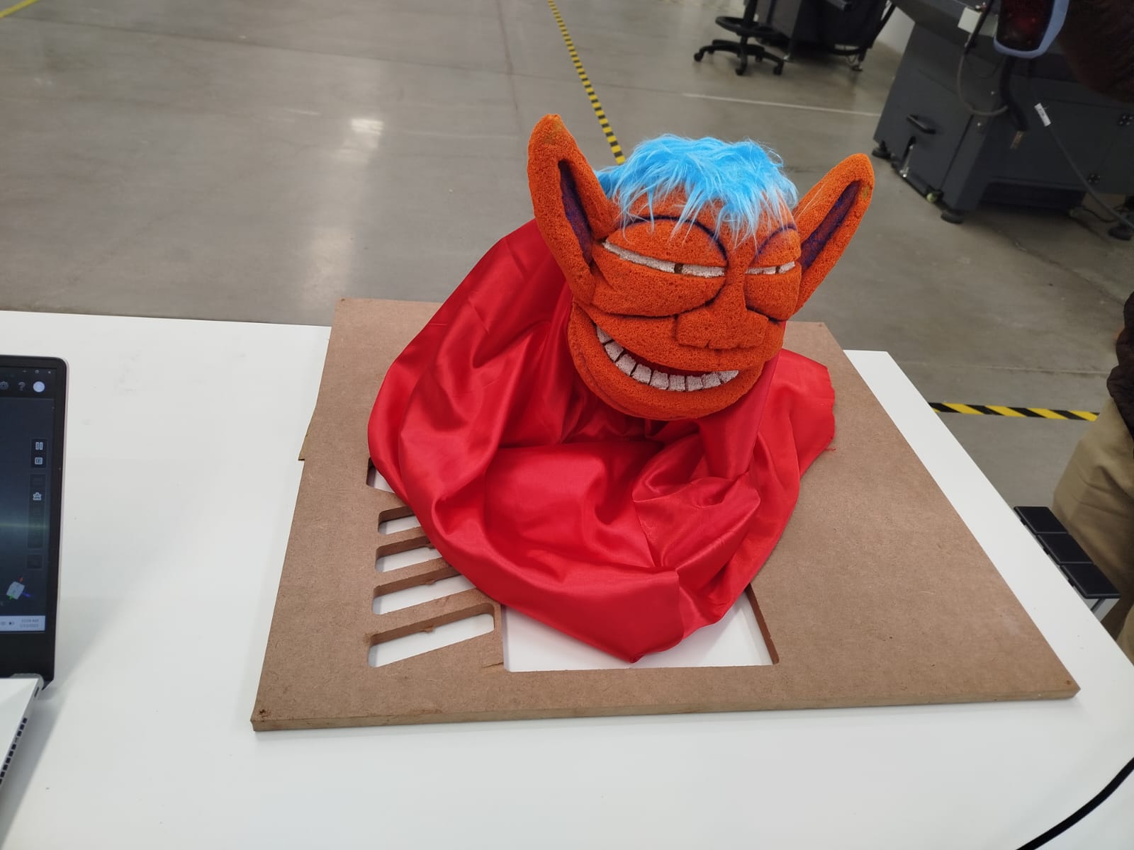
The puppet now features a fully stylized appearance, including orange sponge material for facial texture, synthetic blue hair, and a red satin cape. These elements provide a playful and character-driven visual identity.
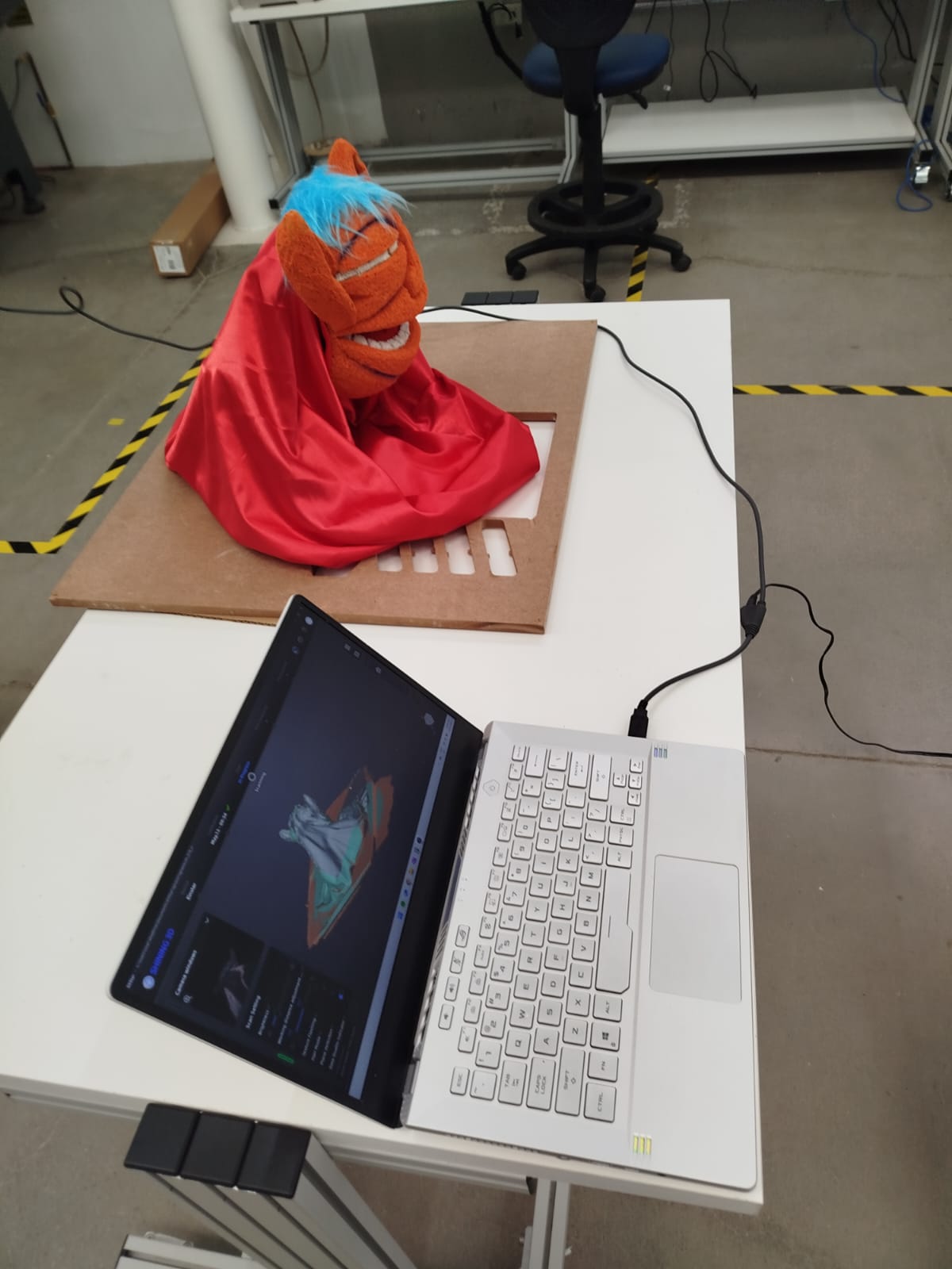
A 3D scan was performed using professional scanning equipment. The result was processed and visualized in software for digital archiving, replication, and potential further enhancements.
The interactive puppet operates through the integration of a microcontroller that coordinates audio playback and servo motor movement, allowing the character's mouth to synchronize with the storytelling. The system includes a sound module with a speaker, a hidden structural base that houses the electronics, and an interchangeable mask mechanism that makes it easy to switch characters depending on the story. During operation, the puppet creates an immersive and expressive experience for the audience, especially in educational settings. While the current performance is satisfactory, adjustments to the audio-motion synchronization and additional testing are needed to ensure system stability and durability over extended use.
The result is a robust, expressive, and modular puppet prototype that fulfills all the functional and aesthetic goals set at the beginning of the project. With only the installation of the final electronics and decorative enhancements remaining, the puppet is ready for public presentation, educational demonstrations, and future iterations.
The prototype is designed as a modular, maintainable system. The final packaging will include casing for electronics, removable face modules, and wireless control. It has been crafted to reflect a product-oriented approach suitable for educational contexts.
This week marked a key milestone in the development of the final project: the successful integration of mechanical, electronic, and structural components into a single functional system. By combining 3D-printed parts, laser-cut wooden supports, and servo-driven control, a minimum viable prototype of the puppet was achieved.
The project demonstrated the feasibility of synchronizing mouth movement with potential audio signals through a mechanically stable and aesthetically coherent structure. The integration of the servo mount, linkage mechanism, and modular puppet head validated the core mechanical functionality and set a solid foundation for the upcoming tasks.
This integration phase confirmed that the system architecture and physical assembly can support further development of interactive features, including real-time audio synchronization and mobile app control. While packaging and enclosure design remain in progress, the current prototype already reflects a product-oriented design suitable for educational storytelling.
The focus for the upcoming weeks will be on refining movement expressiveness, programming synchronized audio control, and developing the final casing. Overall, the integration process validated the conceptual and technical design, reinforcing the project's educational and creative goals.
Click the button below to access and download all available materials.
Download Resources