Week 17: Project Development
This page answers the following questions:
- What tasks have been completed?
- What tasks remain?
- What has worked? What hasn’t?
- What questions need to be resolved?
- What will happen when?
- What have you learned?
What tasks have been completed?
Main part of design of each part is done (please refer to week 15)
- Candy dispenser mechanism design
- Design of Robot / Project Head
- Project Board Design with ESP32-C6
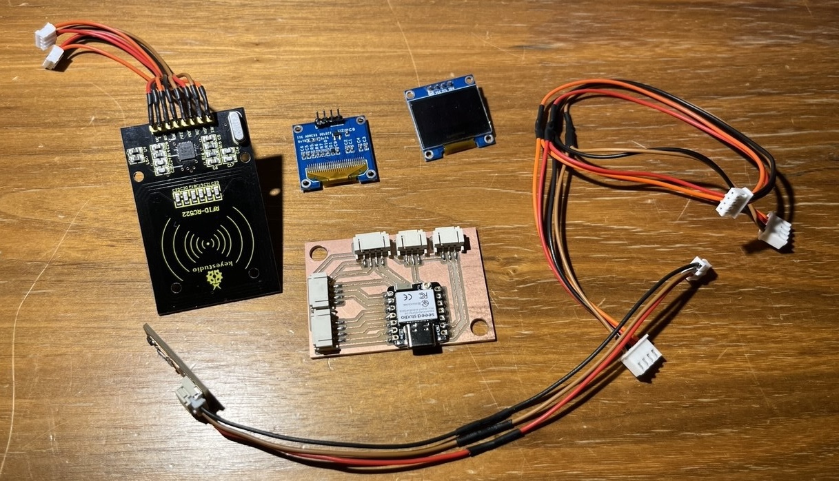
Electronics from Kerala:
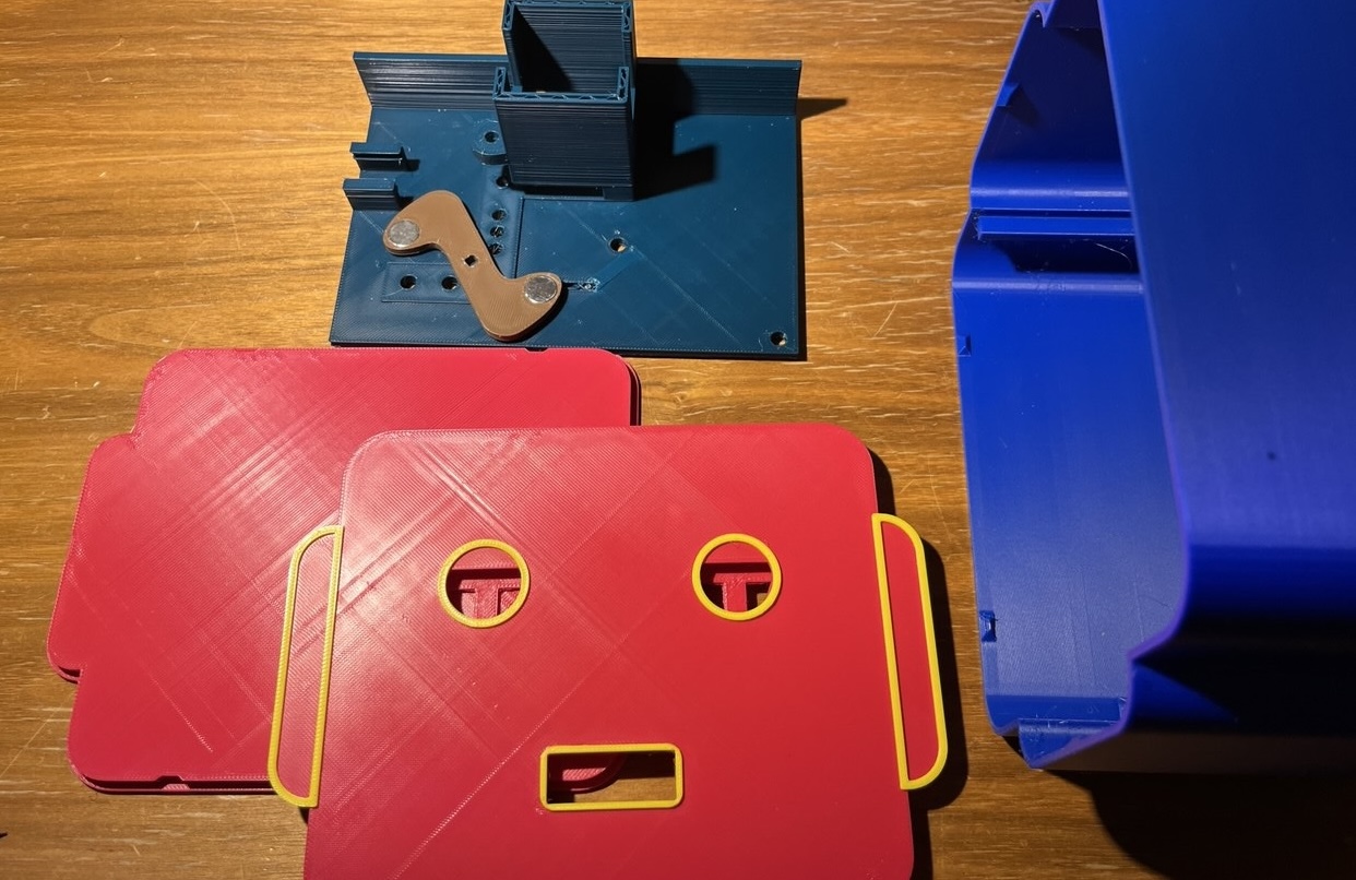
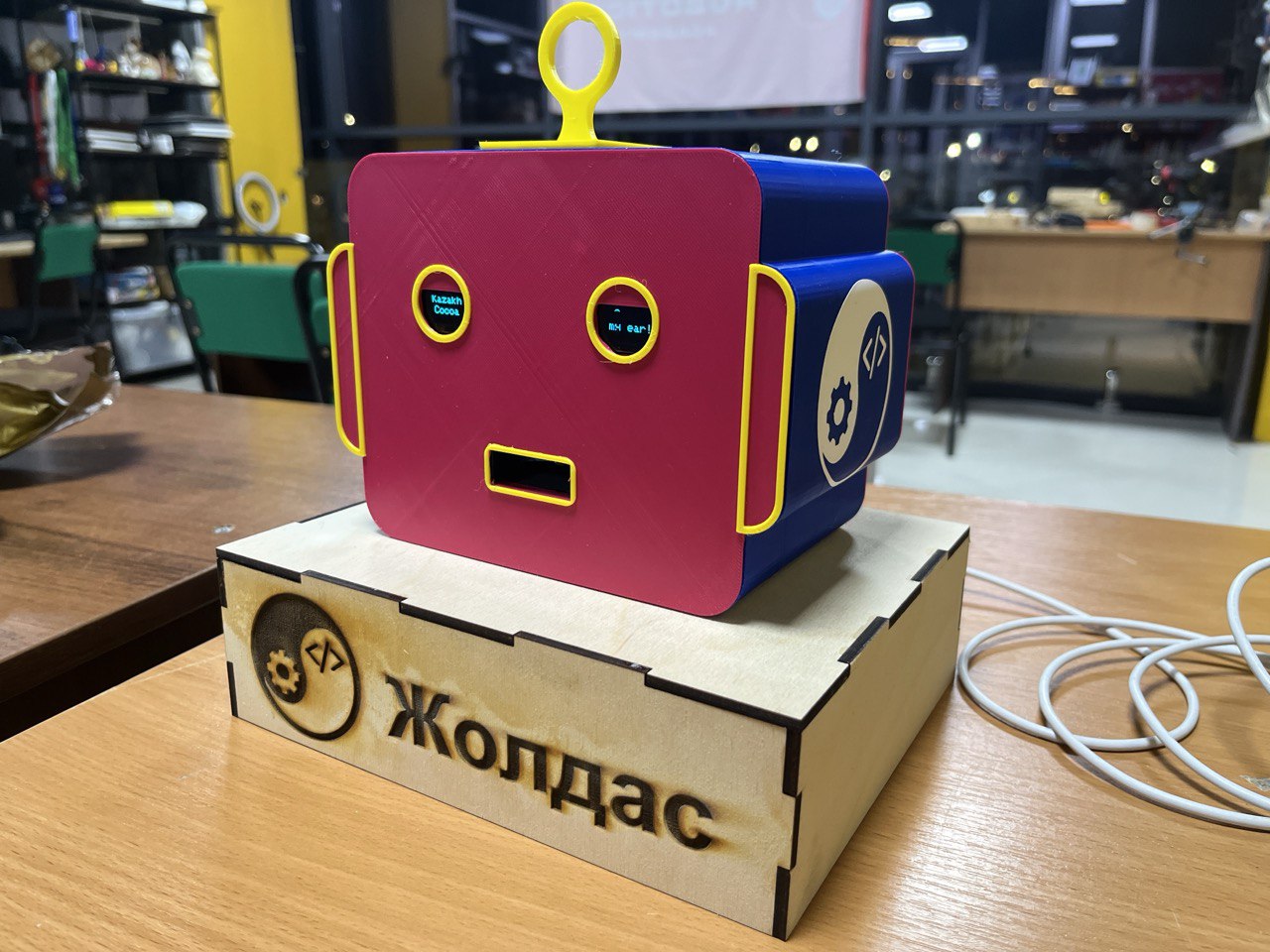
3D-printed body / packaging:
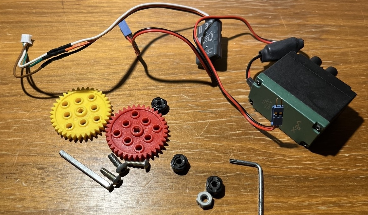
.. and pieces from an old VEX kit:
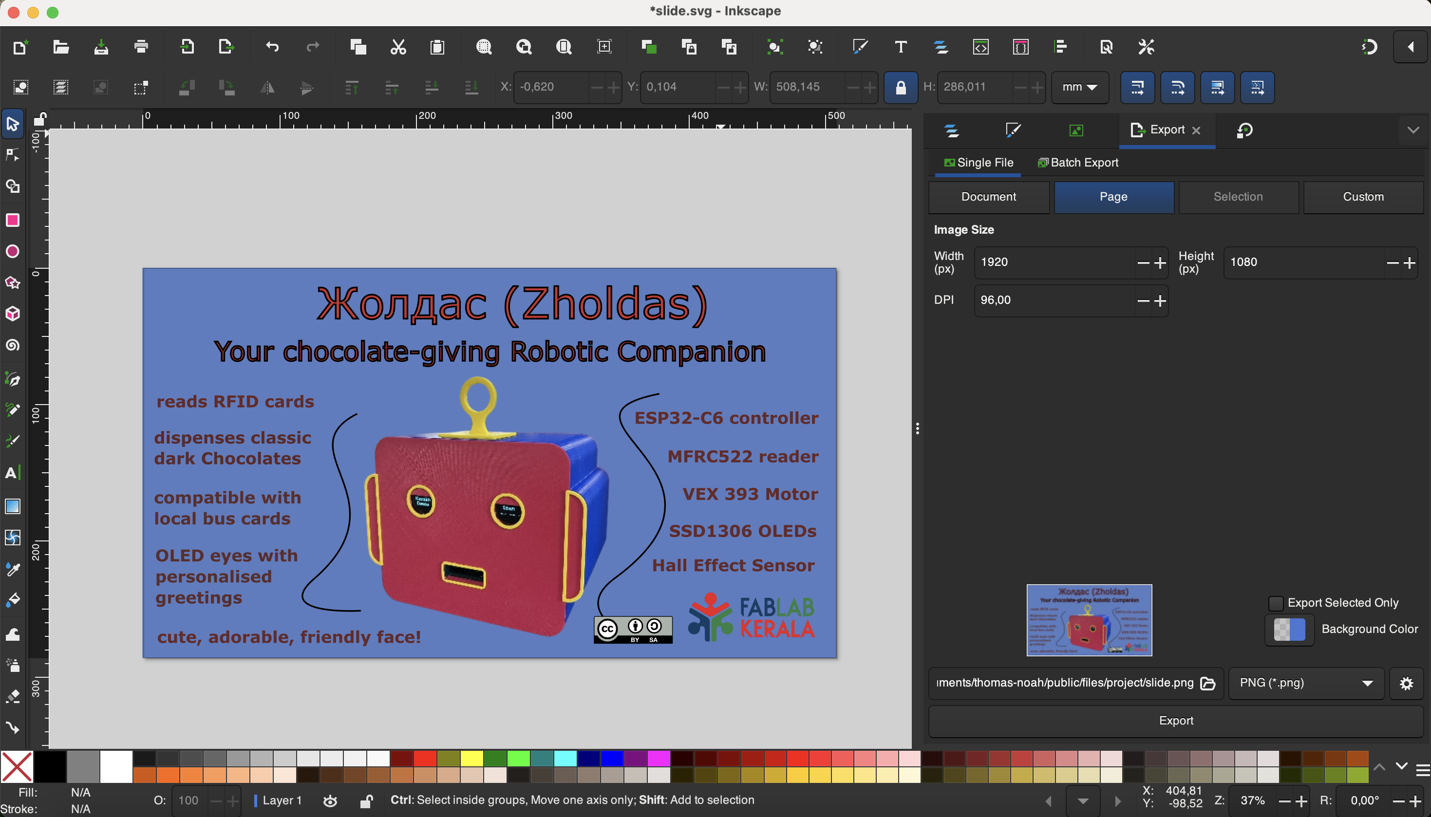
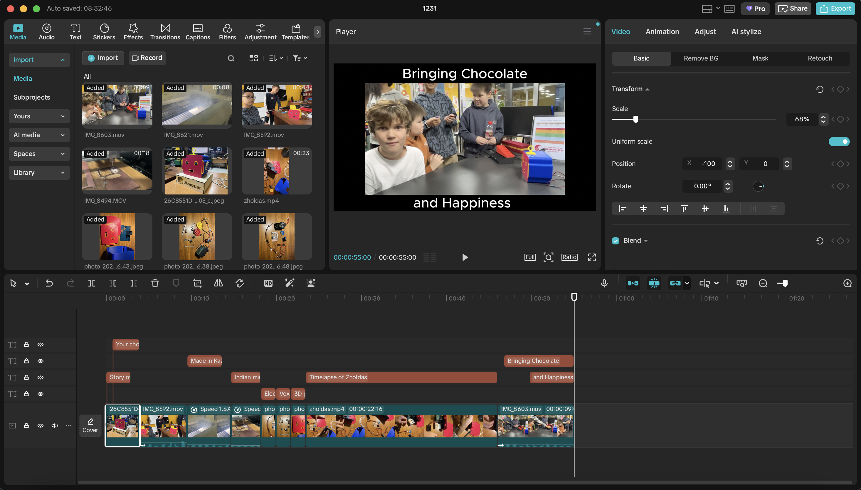
The slide and video are also now complete. Both are there on the main project page.
I used inkscape to create the slide...
..and capcut to produce the video.
What tasks remain?
Generally the project is done. What remains is to continue rearranging the documentation so as to fit requirements.
We can also continue to program. We are continually adding RFID cards to the system to enable more users, i.e. children able to receive chocolate. There was also a need to add a time-out function to the cards because boys would just take all the chocolates. Now they must wait 2 minutes and this time can of course also be adjusted. We also have super-cards which do not have a time-out; these are for teachers who may need to access more chocolates. See below for deep-dive into programs.
What has worked? What hasn't
Bambu Lab A1 Mini has worked amazingly well, and we are familiar with its operation. Designing part of the head from a laser-cutter has not worked out because it will be block-like and creepy. But that is fine and actually will be more professional to produce the head casing through 3D-printing.
What hasn't worked well, neither for my state of mind nor for project development, is the continual need to rearrange documentation. Perhaps it makes sense if the documentation was done in this format in the actual week ("Document while you work"). But at this point it doesn't make sense to spend time on it. Probably I will later produce documentation which has clear sections like "Mechansim design", "Programming" etc. so that interested readers can clearly and easily explore the parts of the project of interest to them.
What questions need to be resolved?
A main question a month ago is whether or not I could produce a board in time to bring it to Kazakhstan so that I may continue work. In fact the board was successfully produced and soldered in time according to the following BOM:
Another key question is how to integrate subtractive processes in the project. While I had originally conceived the head as a laser-cut production, that in the end proved less professional and aesthetically pleasing than a 3D-printed design. Finally I included two subtractive processes, both laser-cutting and vinyl-cutting, as can be seen in below image:
However these are surface level inclusion of subtractive processes, essentially decorative and not really a part of the main packaging, so there is room for improvement here, and perhaps still something to solve.
What will happen when?
In the first 10 days of December I was in Kerala finishing documentation and also working for the final project. In those days the most important work for the project was designing and producing the project PCB as I knew this was something I could absolutely not do remotely.
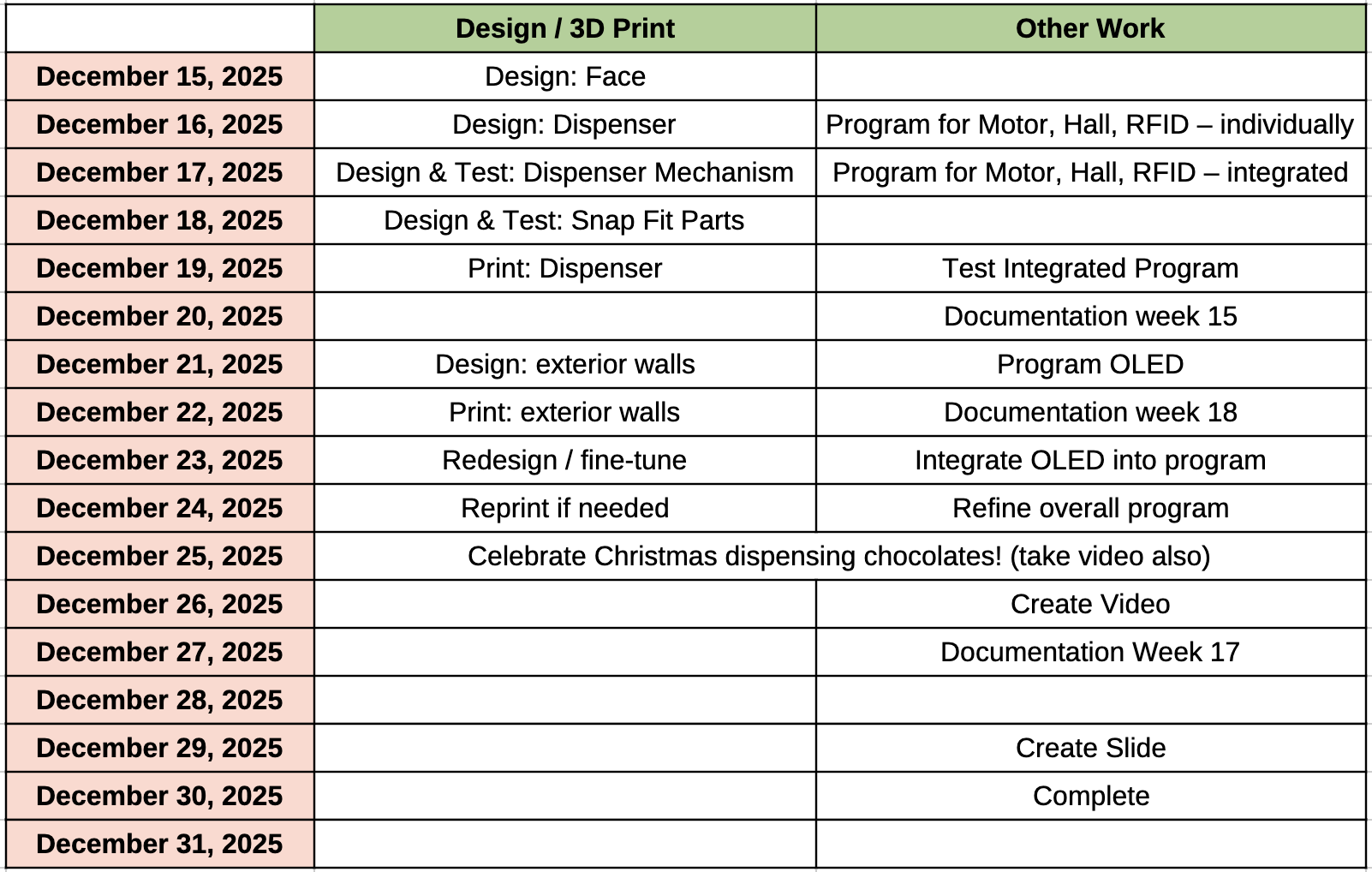
Subsequently I returned to Kazakhstan where I immediately made the schedule of tasks to complete:
What have you learned?
- Fusion 360
- 3D printing
- PCB design
- (re)learning how to focus
- learning to do for understanding not completion
- Too much
Project Programs
The programs were made in Arduino IDE, and with help from perplexity.ai. We used the method of spiral development in our programs we start from using each one of our peripherals, making sure we understood its code and proper use separately before bringing them together.
Here's the minimalistic program to read values of Hall Effect sensor:
void setup() {
Serial.begin(9600);
}
void loop() {
int sensorValue = analogRead(D1);
Serial.println(sensorValue);
delay(1);
}
Here's minimalistic usage of RFID card reader:
#include
#include
#define RST_PIN D3
#define SS_PIN D7
MFRC522 mfrc522(SS_PIN, RST_PIN);
void setup() {
Serial.begin(115200);
SPI.begin();
mfrc522.PCD_Init();
Serial.println("Place your card near the reader...");
}
String uidToString() {
String uid = "";
for (byte i = 0; i < mfrc522.uid.size; i++) {
uid += (mfrc522.uid.uidByte[i] < 0x10 ? "0" : "");
uid += String(mfrc522.uid.uidByte[i], HEX);
}
uid.toUpperCase();
return uid;
}
void loop() {
// Look for a new card
if (!mfrc522.PICC_IsNewCardPresent()) {
return;
}
// Select one of the cards
if (!mfrc522.PICC_ReadCardSerial()) {
return;
}
// Convert UID to string
String UID = uidToString();
// Lookup name by UID (REPLACE these UIDs with your actual card UIDs)
String personName = "Unknown Card";
if (UID == "04A1B2C3") {
personName = "John Doe";
} else if (UID == "83BE0715") {
personName = "Saheen Smith";
} else if (UID == "045A100AD17780") {
personName = "Turkish Delight";
} else if (UID == "057441AF") {
personName = "Mr Tom";
}
// Print to serial monitor
Serial.println("=== CARD DETECTED ===");
Serial.print("UID: ");
Serial.println(UID);
Serial.print("Name: ");
Serial.println(personName);
Serial.println("====================");
Serial.println();
// Halt PICC
mfrc522.PICC_HaltA();
}
Here's the minimal usage of the VEX 393 Motor, used as a servo with values of 1000/1500/2000 for pulse widths. The following program simply rotates the motor in one way for a second, then the other way for a second, with one second pauses in between.
// 360° (continuous rotation) servo control
// for Seeed XIAO ESP32-C6 with ESP32 core 3.x
// Use any suitable digital pin; D2 is fine.
const int SERVO_PIN = D6;
// LEDC (PWM) config
const int LEDC_FREQUENCY = 50; // 50 Hz for servos
const int LEDC_RESOLUTION = 16; // 16-bit resolution
// Pulse widths in microseconds
const int PULSE_MIN_US = 1000; // full speed one direction
const int PULSE_STOP_US = 1500; // stop (tune this for your servo)
const int PULSE_MAX_US = 2000; // full speed other direction
// Convert microseconds to LEDC duty value
uint32_t pulseUsToDuty(int us) {
const float periodUs = 1000000.0f / LEDC_FREQUENCY; // 1/f (50 Hz -> 20000 us)
uint32_t maxDuty = (1 << LEDC_RESOLUTION) - 1; // e.g. 65535 for 16-bit
return (uint32_t)((us / periodUs) * maxDuty);
}
// Set servo pulse width
void setServoPulse(int us) {
uint32_t duty = pulseUsToDuty(us);
// In core 3.x, ledcWrite takes the *pin* instead of the channel
ledcWrite(SERVO_PIN, duty);
}
void setup() {
Serial.begin(115200);
delay(1000);
Serial.println("XIAO ESP32-C6 360-degree servo demo (core 3.x)");
// New API in ESP32 core 3.x:
// ledcAttach(pin, freq, resolutionBits)
ledcAttach(SERVO_PIN, LEDC_FREQUENCY, LEDC_RESOLUTION);
// Start with servo stopped
setServoPulse(PULSE_STOP_US);
}
void loop() {
Serial.println("Stop");
setServoPulse(PULSE_STOP_US);
delay(1000);
Serial.println("Rotate direction A (full speed)");
setServoPulse(PULSE_MIN_US); // one direction
delay(1000);
Serial.println("Stop");
setServoPulse(PULSE_STOP_US);
delay(1000);
Serial.println("Rotate direction B (full speed)");
setServoPulse(PULSE_MAX_US); // opposite direction
delay(1000);
}
Finally, here's the minimal usage of OLED displays
#include
#include
#include
#define SCREEN_WIDTH 128
#define SCREEN_HEIGHT 64
#define OLED_RESET -1
// Display 1 at address 0x3C (default)
Adafruit_SSD1306 display1(SCREEN_WIDTH, SCREEN_HEIGHT, &Wire, OLED_RESET);
// Display 2 at address 0x3D (modified)
Adafruit_SSD1306 display2(SCREEN_WIDTH, SCREEN_HEIGHT, &Wire, OLED_RESET);
void setup() {
Serial.begin(115200);
// Init display 1
if(!display1.begin(SSD1306_SWITCHCAPVCC, 0x3C)) {
Serial.println(F("Display1 failed"));
for(;;);
}
// Init display 2
if(!display2.begin(SSD1306_SWITCHCAPVCC, 0x3D)) {
Serial.println(F("Display2 failed"));
for(;;);
}
display1.clearDisplay(); display1.setTextSize(1); display1.setTextColor(SSD1306_WHITE);
display1.setCursor(0,0); display1.println(F("Display 1 - Temp")); display1.display();
display2.clearDisplay(); display2.setTextSize(1); display2.setTextColor(SSD1306_WHITE);
display2.setCursor(0,0); display2.println(F("Display 2 - Uptime")); display2.display();
}
void loop() {
// Update Display 1 (e.g., fake temp)
display1.clearDisplay(); display1.setCursor(0,0);
display1.print(F("Temp: ")); display1.print(random(20,30)); display1.println(F("C"));
display1.display();
// Update Display 2 (uptime)
display2.clearDisplay(); display2.setCursor(0,0);
display2.print(F("Uptime: ")); display2.print(millis()/1000); display2.println(F("s"));
display2.display();
delay(1000);
}
After verifying that each of 2 input and output sensors work, we can proceed to combine and develop their use in an overall program which we were successful in doing with the help of AI. As this program is considerably longer, we've attached it below, with the transcript of the conversation with AI that created it. But we subsequently spent time to understand the program in detail and edited it further according to need.
Files
Project ProgramConversation with AI