Week 13: Molding & Casting
Group Assignment: review the safety data sheets for each of your molding and casting materials, then make and compare test casts with each of them & compare mold making processes
Individual Assignment:
- design a mold around the process you'll be using
- produce it with a smooth surface finish that does not show the production process toolpath
- use it to cast parts
Reflection on Group Assignment
Of course I was not there in Kerala for this week, however, I later returned and completed this week's activities (as documented above). Besides Revi, who helped with machining the positive mold, Namita helped with the negative mold, so it was very kind of these group-mates to assist. Their assistance together with the group's thorough documentation allowed me to understand all the basic ideas which they covered. The only thing I was unable to do was a test cast of each material.
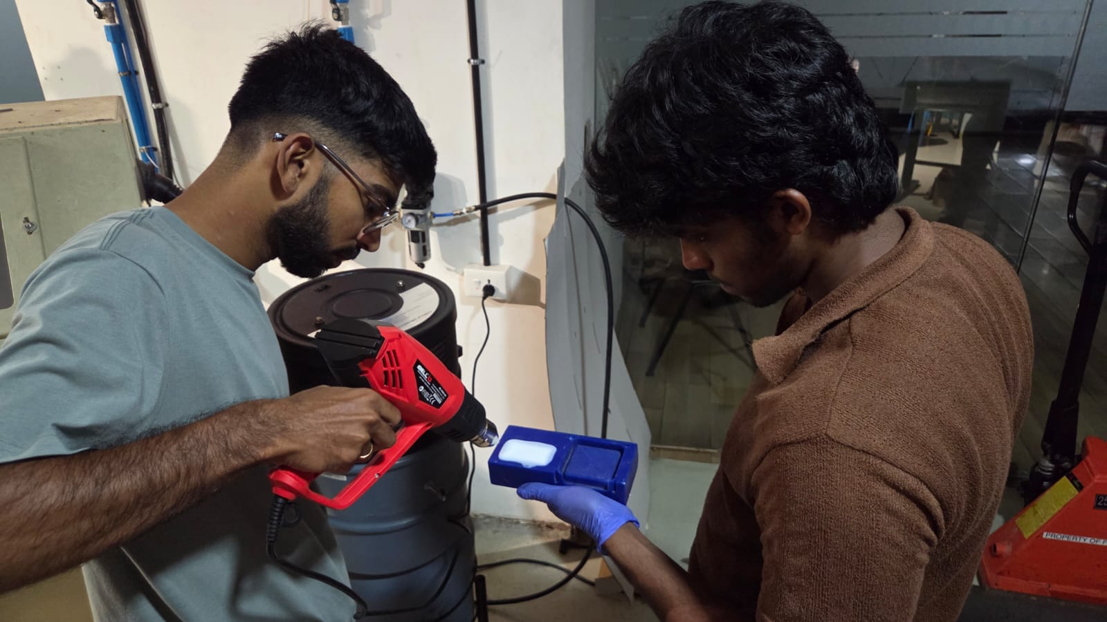
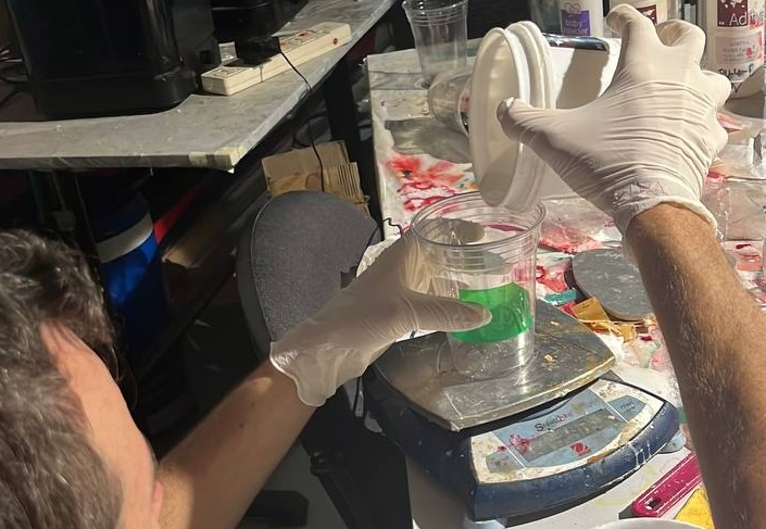
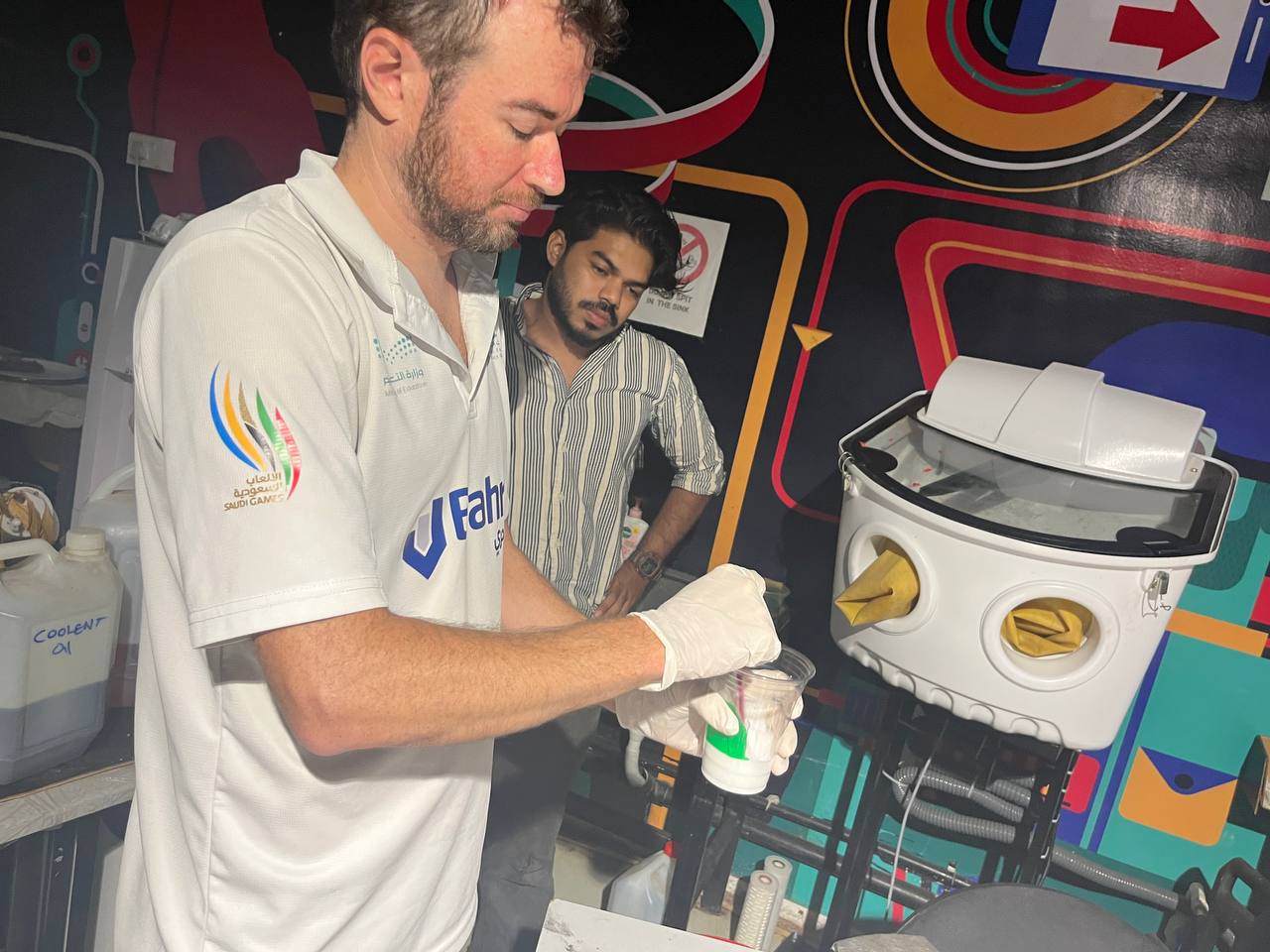
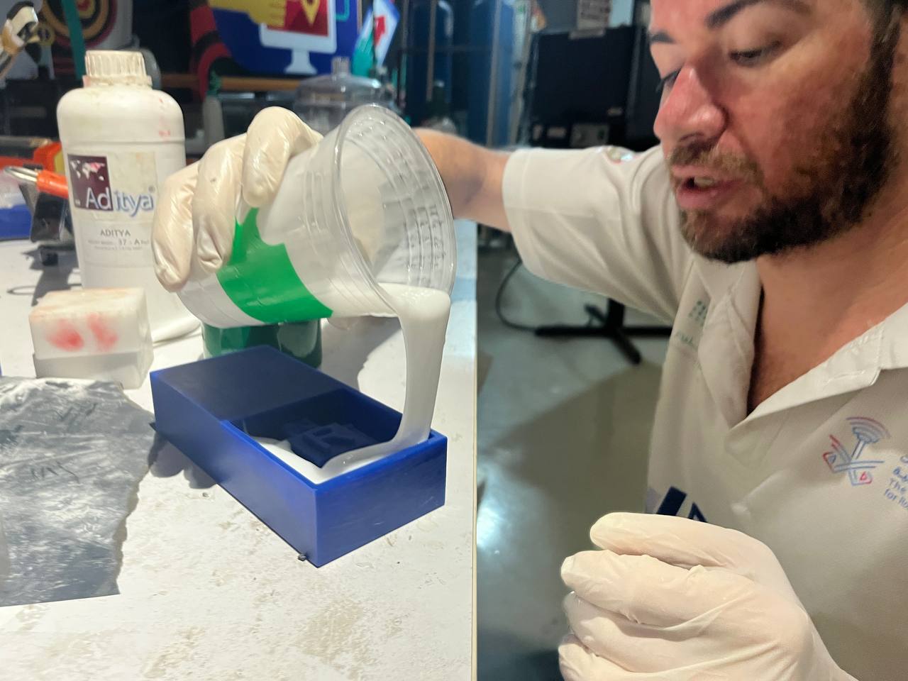
The main molding material used was silicone, and the main casting material a kind of epoxy resin. Both of them being chemical compounds, safety was a priority. There was a dedicated area of the lab for that, and of course not next to the eating area! Additionally we wore gloves, and disposed of materials responsibly. In the below image, Akash demonstrates proper use of gloves for safety while he and Ashish work together to remove excess bubbles in the silicone.
I will additionally document further down on this page some of the same aspects of the process which they documented on the group page, such as methods to find the amount of material to cast and the vacuuming process.
Design a mold:
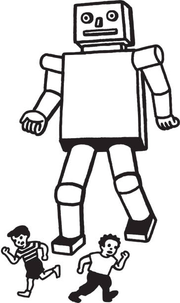
First we need to make a design, it should have a flat back, and should not have overhangs in order for the mold to be made. After some thought we decided on a Robot figure based on the following "scary" robot. image credit.
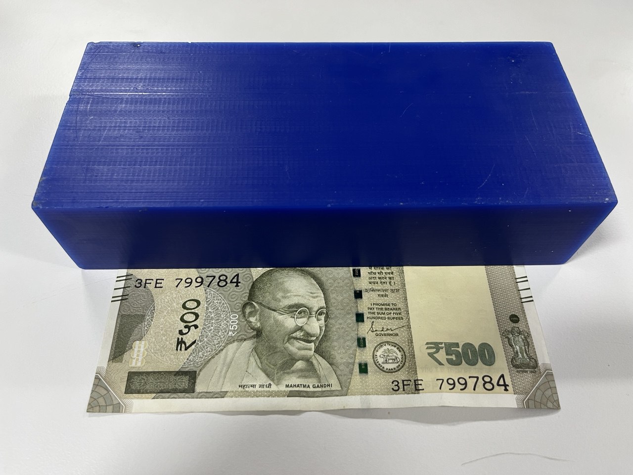
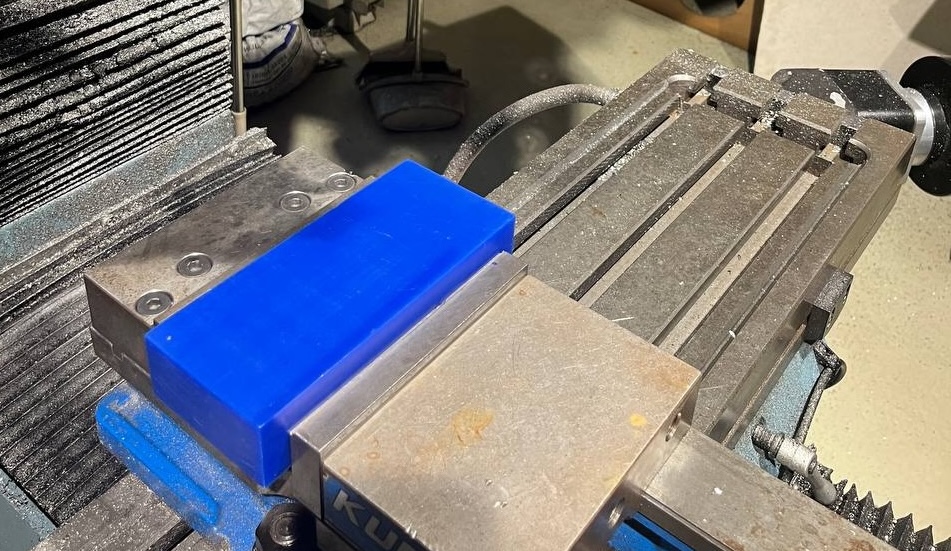
We have the following blue wax block (77 mm x 178 mm x 39 mm) from which is should be molded. Indian 500 Rupee note shown for size reference.
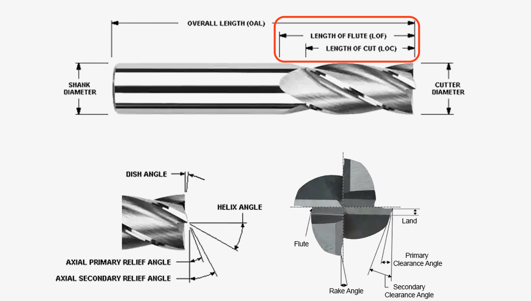
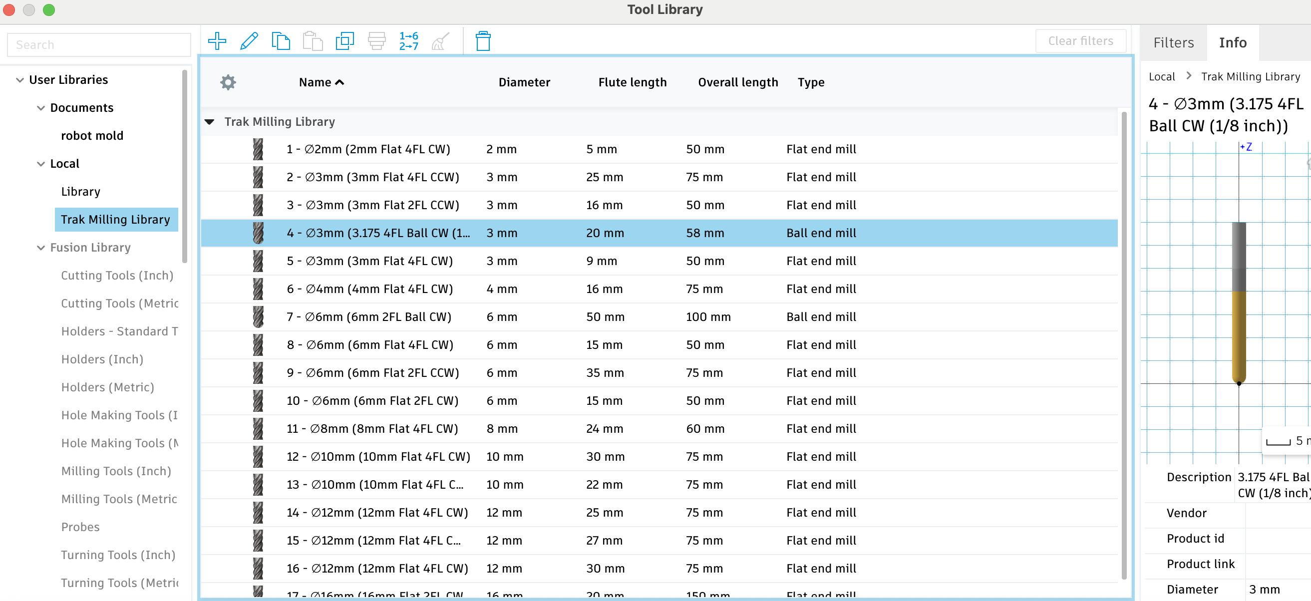
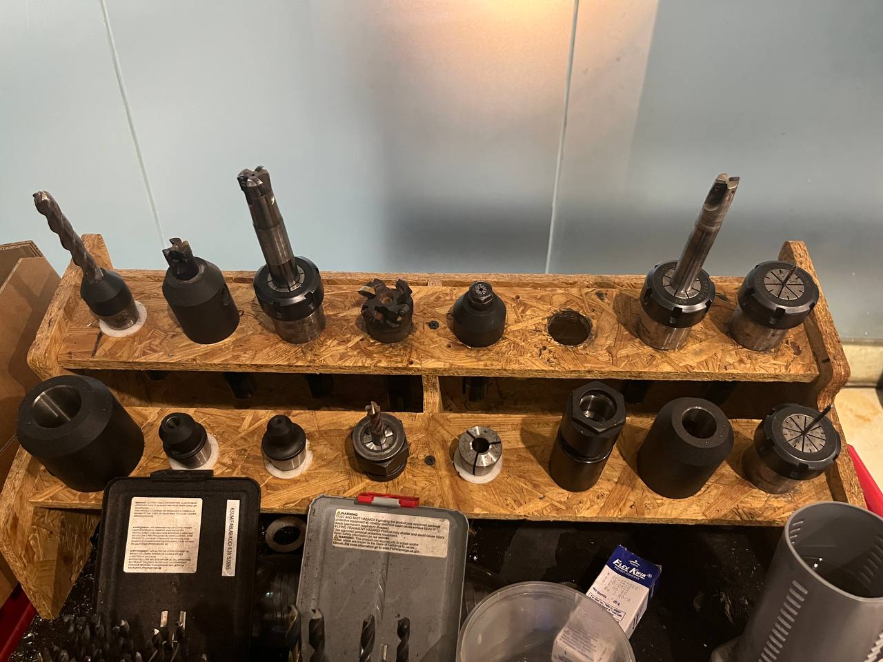
Tool bits are another limitation to our possible designs. Let us consider this diagram of the end mill tool bit to understand more; specifically length of flute and length of cut. These lengths of flute and cut limit the depth which we may mill with the bit, and since the 1 mm bits have a small flute length, we will not be using them, but instead will use a 3mm diameter flat bit and should design accordingly. We will additionally be using a 10mm flat to clear additional material in large areas, and a 3mm ball head bit to make some smooth curves.
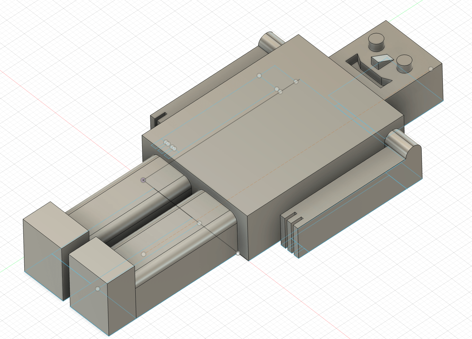
Here is our design which we modeled in Fusion 360, including some rounded edges on the legs and shoulders as we knew this could be manufactured using a round-headed bit. However, we were neglectful of the aforementioned constraints and had added some crude fingers, with a very small 1mm gap between the fingers, which could be done by a 1 mm bit, but not to the depth we showed in the design. We also have a small margin (less than 2 mm) between the legs and between head / shoulders which needs to be rectified.
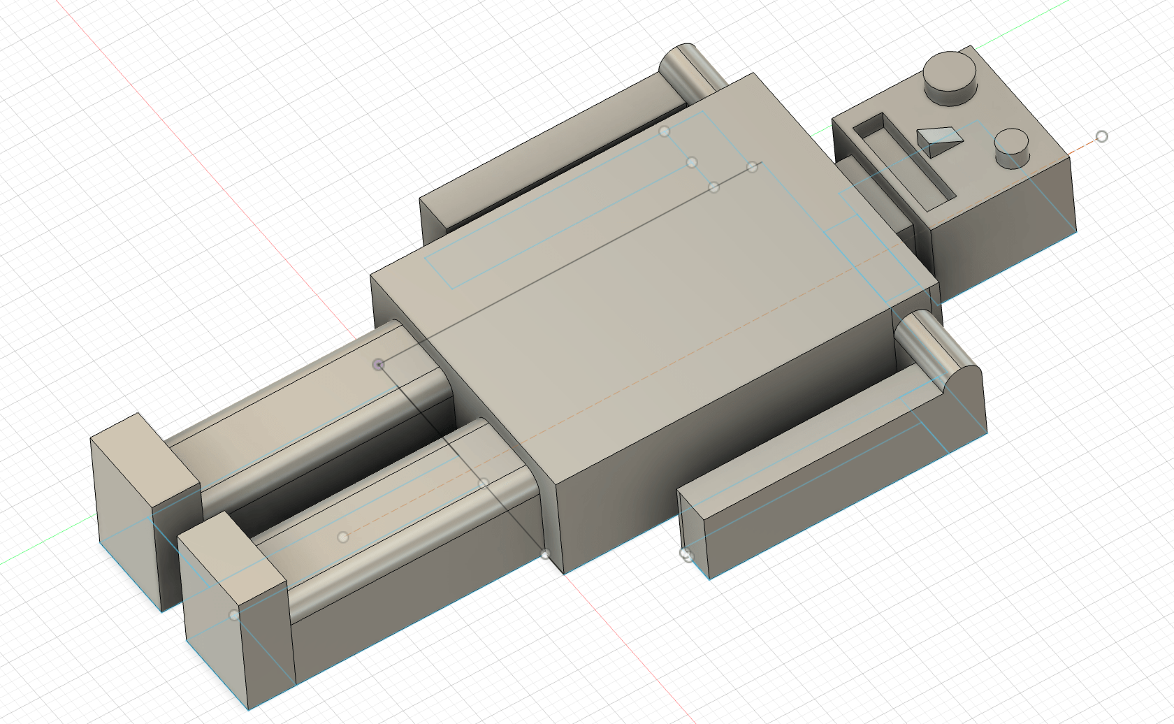
Here is our reconfigured (and perhaps scarier?) version, and meeting the design constraints:
Preparation for the Milling Job
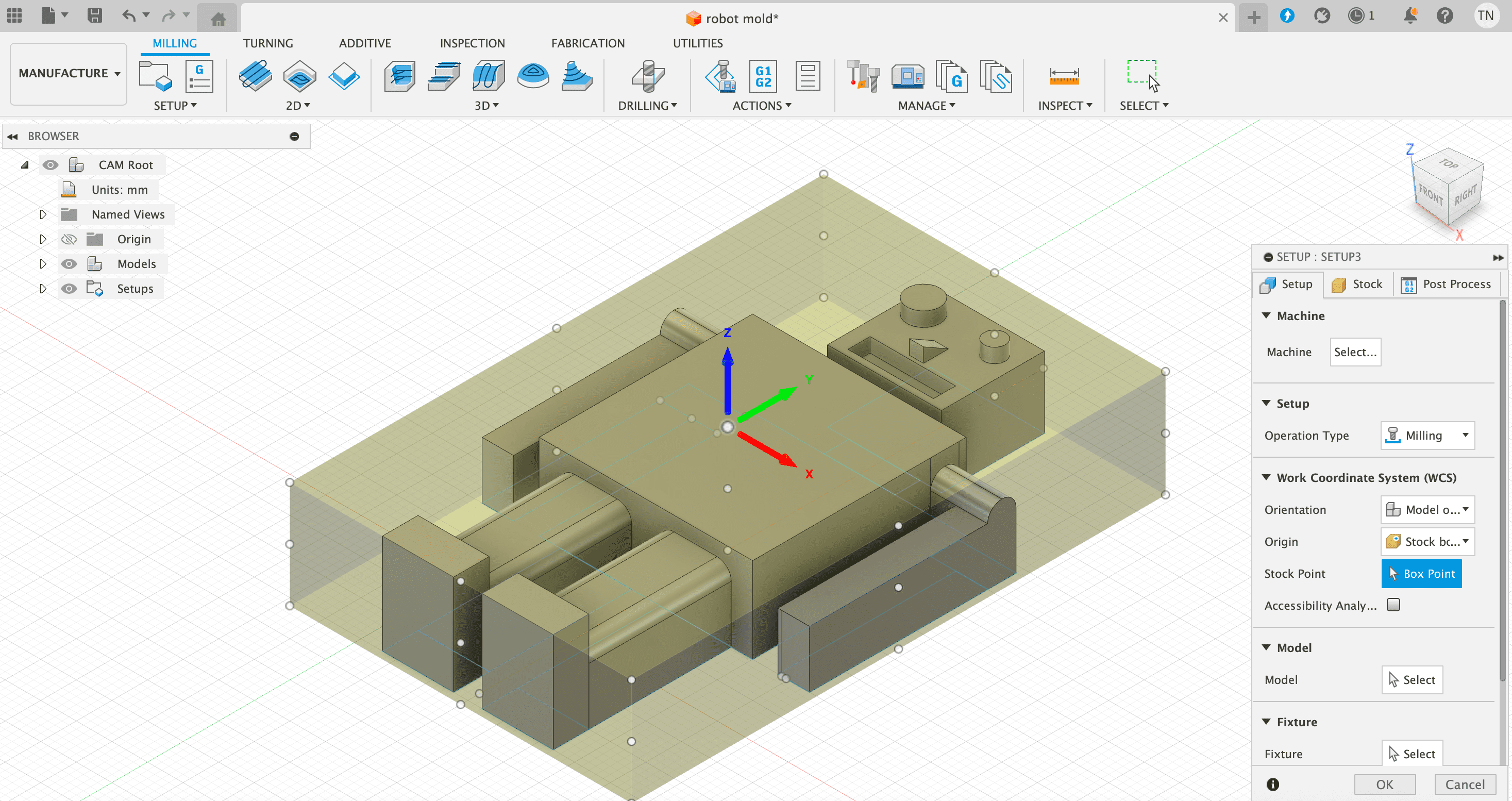
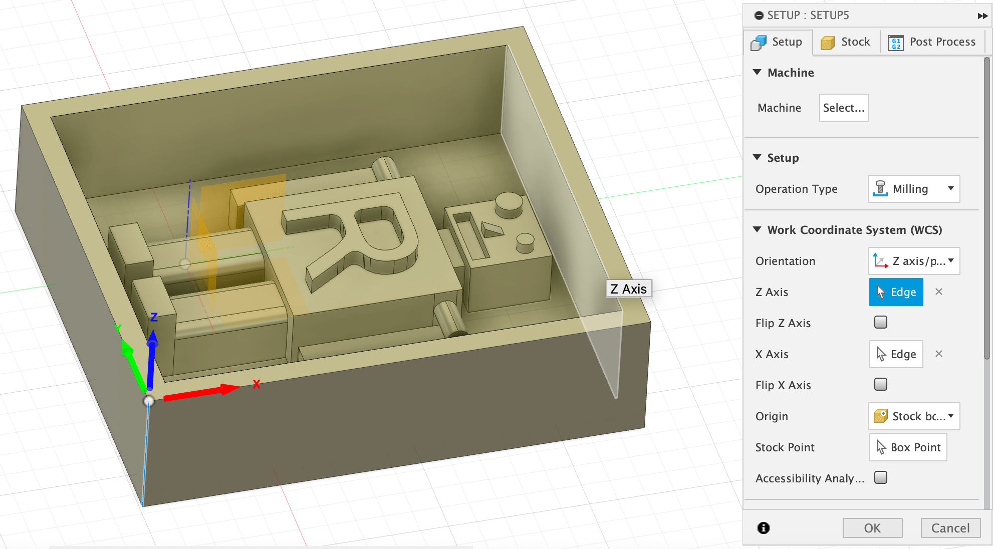
Having completed the design, we enter the CAM, or "Manufacture", section of Fusion 360 and create a new setup, choosing "milling" as the operation type. Fusion 360 is unique from modeling software in that it has CAM processes integrated in this way.
Revi next helped us to import the available tools (link in downloads). To import, we simply navigate to "Manage"->"Tool Library"; from there right-click on library and select "Import libraries".
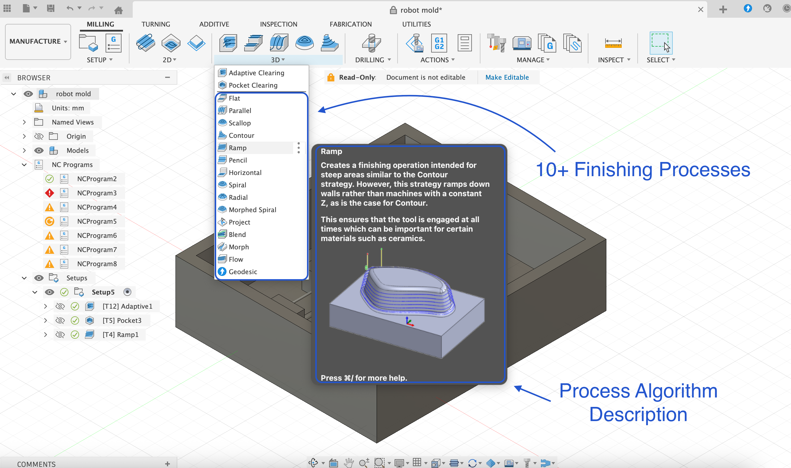
Subsequently the next important part is to define and choose the different processes which will enable us to mill the project as desired. The setup for any milling process will include both rough and finished processes. Our particular setup for this project will include 3 processes as shown in the image below: adaptive, pocket and ramp. Every process has an associated algorithm which defines how it will clear material, and an explaination for each is nicely available within Fusion as shown.
Now we will go through the three different processes and in order, noting also the different toolhead required for the completion of each process.
Rough Cutting:
Adaptive Clearing is the first process and for which we use a larger 10mm flat drill bit. This process can quickly remove a large amount of material in the areas which we must clear of more material. For our project, the key areas which we must clear of more material are in the 4 corners of the workspace as shown.
Pocket Clearing is the second process and it also falls under the category of rough cutting. However for pocket clearning we use a considerably smaller tool, a 3mm flat, and it removes material in more detail around the Robot's body as shown below.
Finish Cutting:
Ramp is the third process and this is a finishing process which gives refined shape like curves to the form. Considering our project, this process gives rounded form to the shoulders, legs and nose of our dear Robot. Note that there are many possible finishing processes, each according to an algorithm to achieve the aim of giving a finished appearance to the project.
Rounded bits are generally used for finishing processes and accordinly we choose a 3mm rounded bit for it.
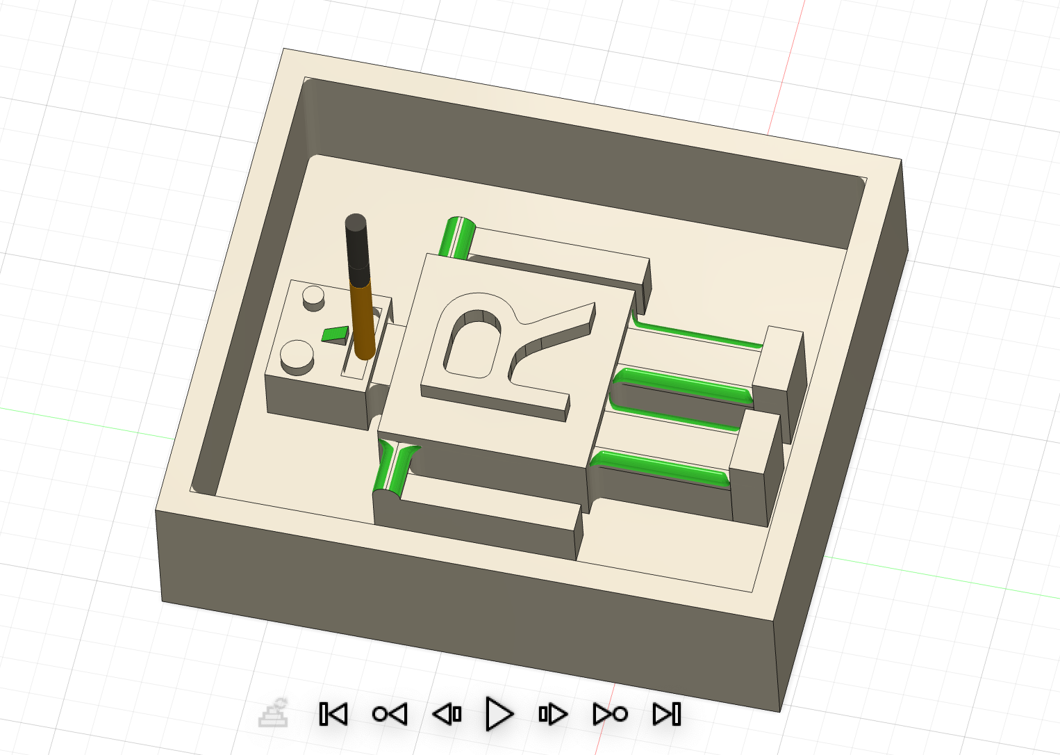
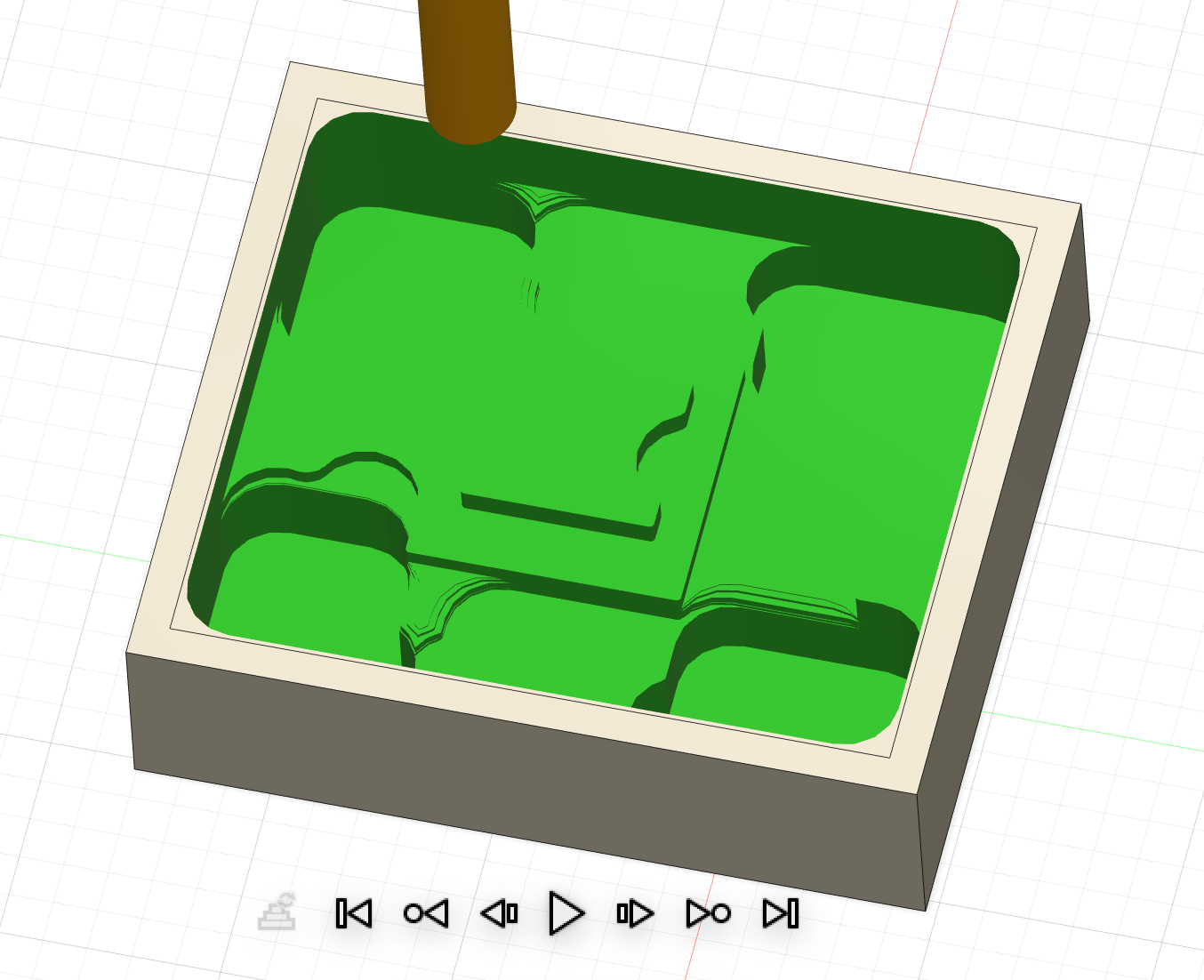
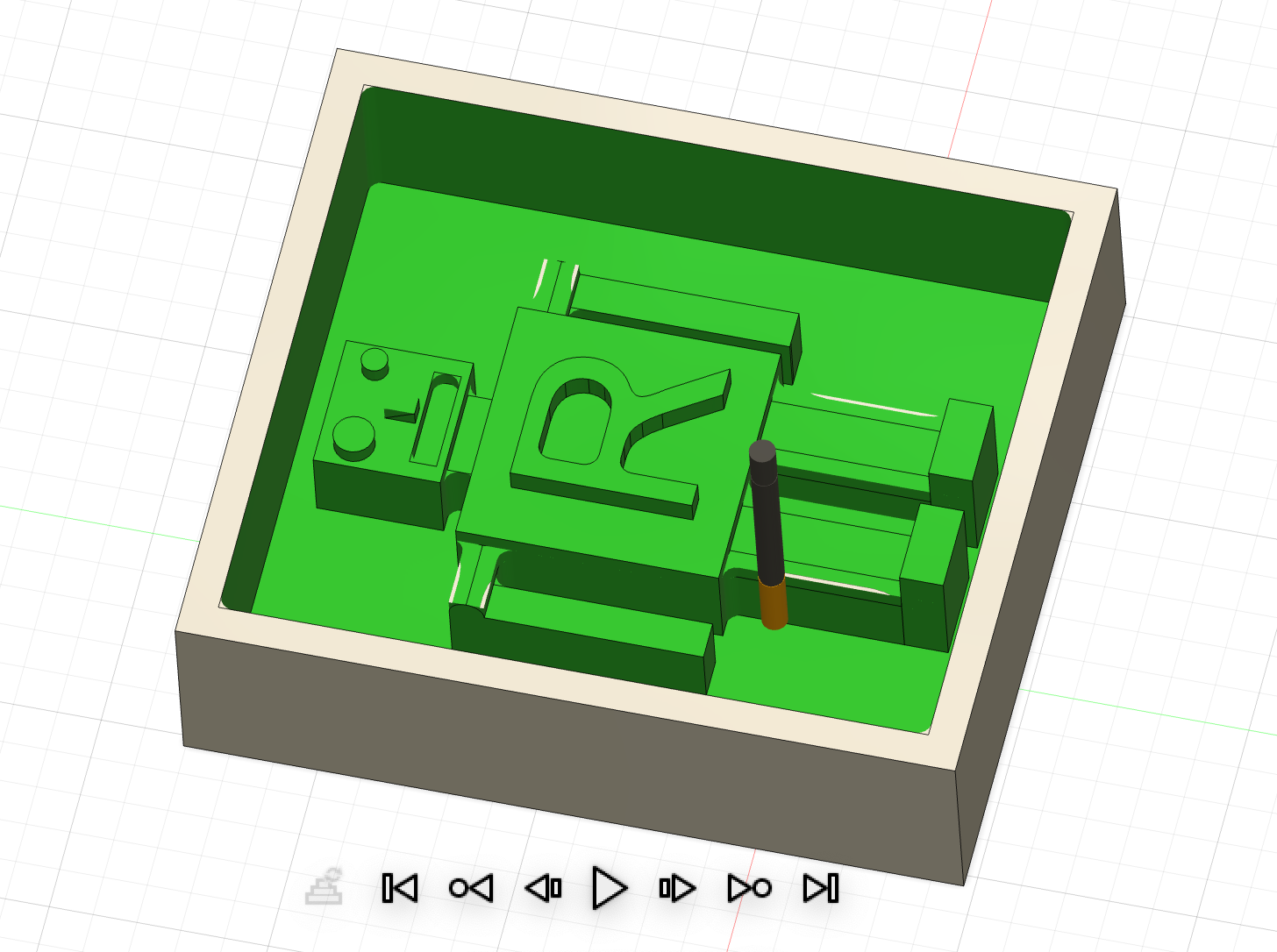
Here is an overall simulation of the 3 stages:
Making the Positive Mold with ProtoTRAK and Revi:
Here's the glamour shot of Revi, setting up the machine.
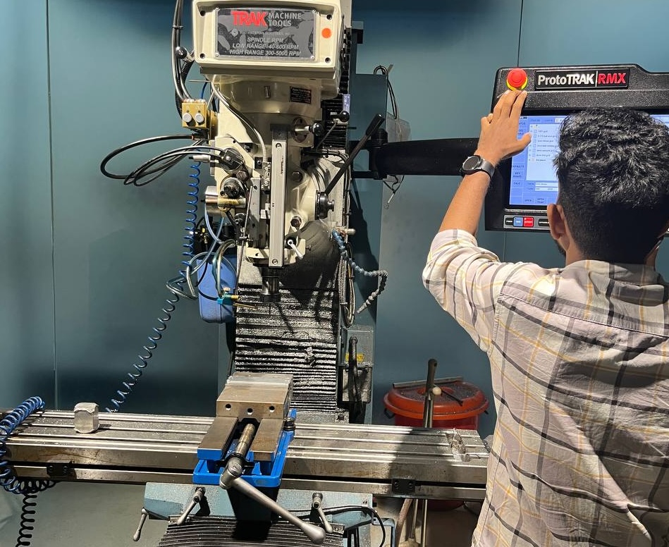
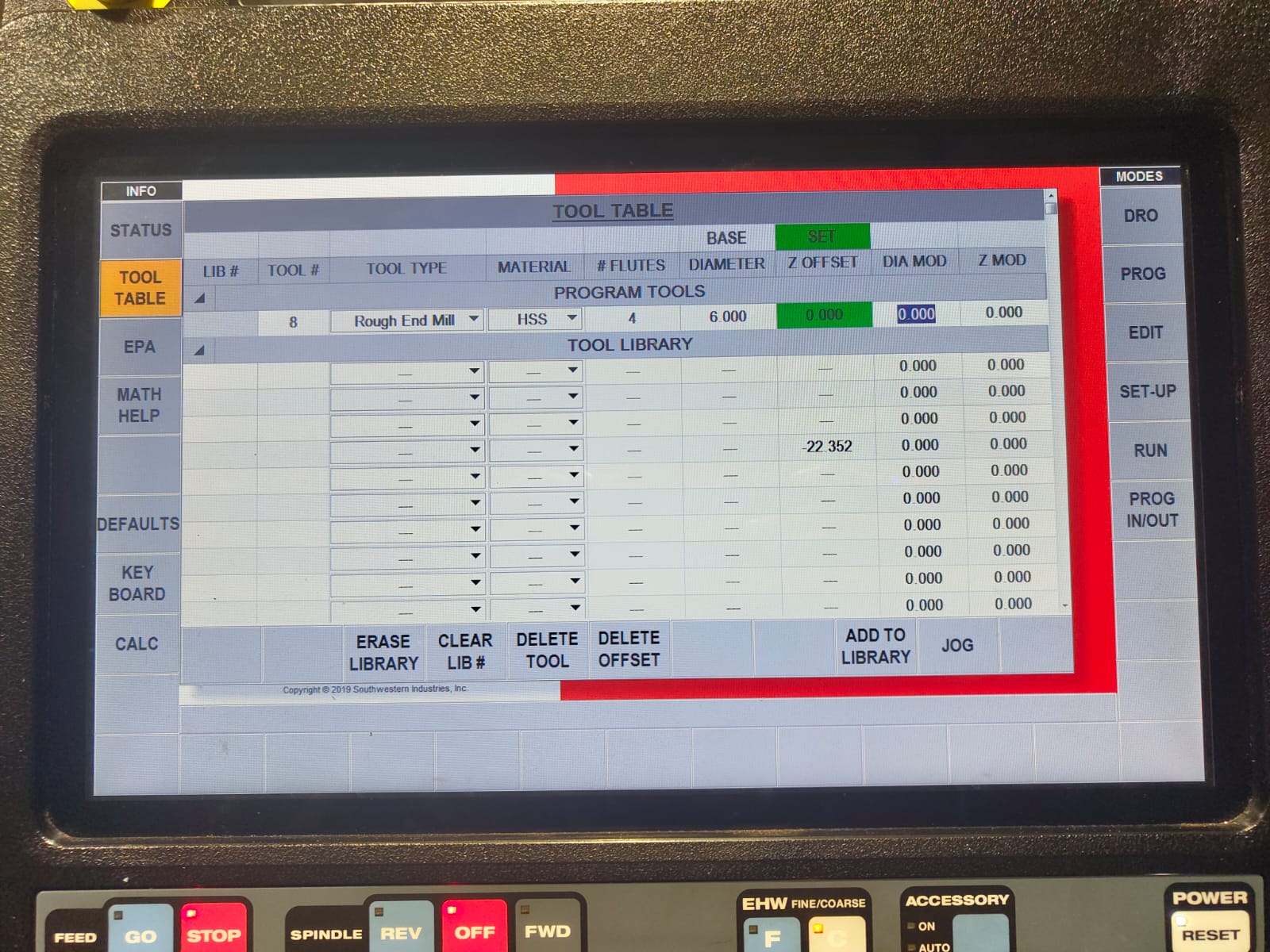
There were a lot of settings as shown in the image below from Revi, please refer his documentation. The key aspect of setting up is to have the appropriate toolheads for the parts of the job.
Continuing the process, our allotted wax block must first be clamped in the vise:
Shown below is the selection of available tools, their variety is key for the parts of the job and needed level of precision. As mentioned in the previous section, we'll be using 3 of these toolheads: 10 mm flat, 3 mm flat, and finally the 3mm rounded bit to create the rounded edges of our mold.
Rough Cutting:
Here is a short clip of the first "adaptive" process of the milling job, with 10 mm bit. Amazing that such a big machine could mill with such precision!
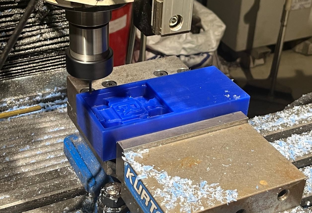
This picture shows the progress in the middle of the "pocket" process, as more precise outline of the Robot begins to emerge. The letter R is clearly visible, and just about to mill the area between the legs and arms which will complete the rough cut stage of the milling job.
Finish Cutting:
This final shot shows the finished result after the "ramp" process creating the curved edges. Amazing!

Making the Negative Mold from Silicone:
We will use Silicone from Aditya company, specifically their "Rubber RTV - 1010", mixed with a small amount of a compounding agent.
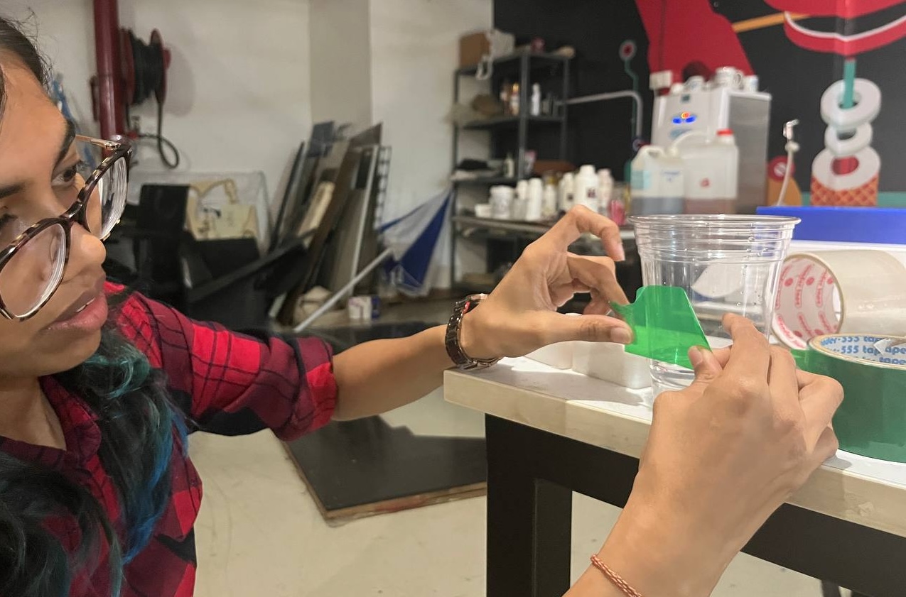
First we'll need to calculate the amount of silicone material to produce. For this a clever technique to fill the positive mold with water and subsequently pouring that water into a cup and marking the level. Namita helped. She's very nice.
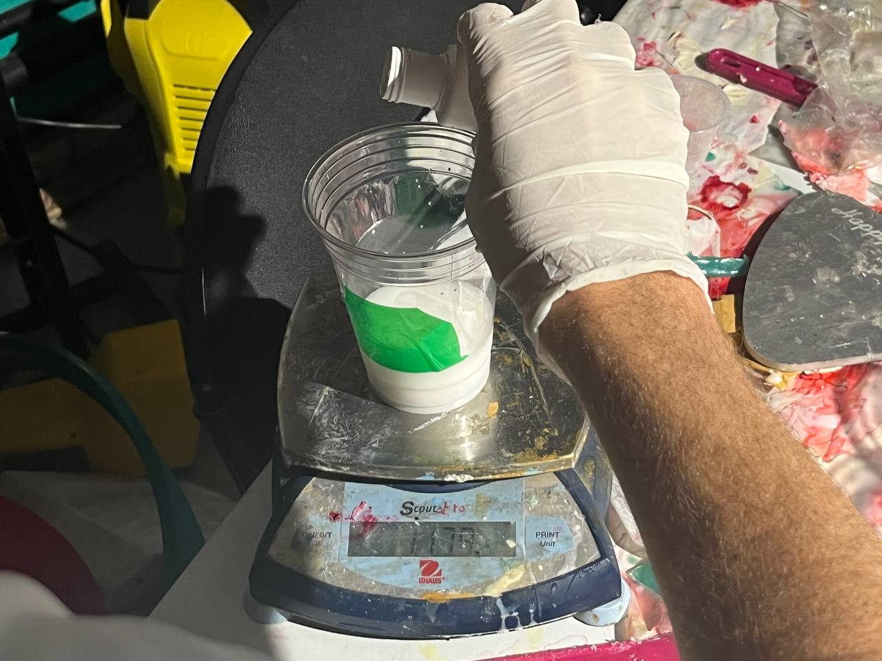
Now we pour the silicone to that level:
And put the cup on a scale to weight it:
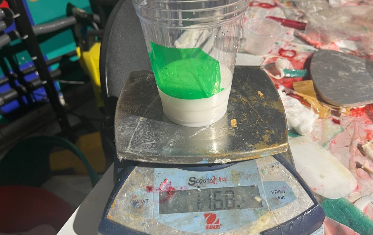
This enables us to add the appropriate amount of the curing agent. Here we had 116.8 grams of silicone and added 3.2 grams of the agent:
Then mixed it well under the watchful eyes of Mufeed:
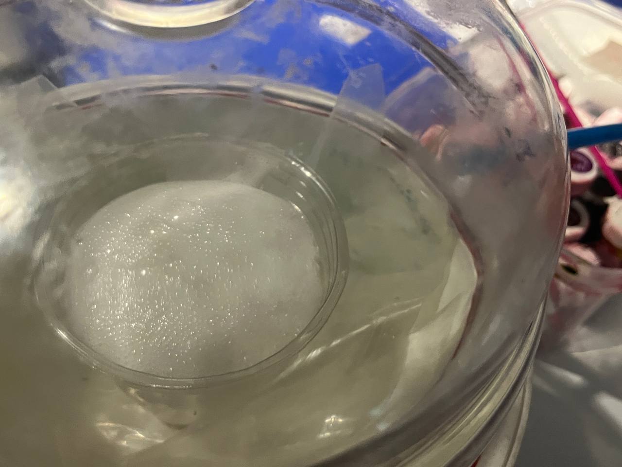
Vacuumed out the bubbles / air pockets with a degasing chamber from Aditya.
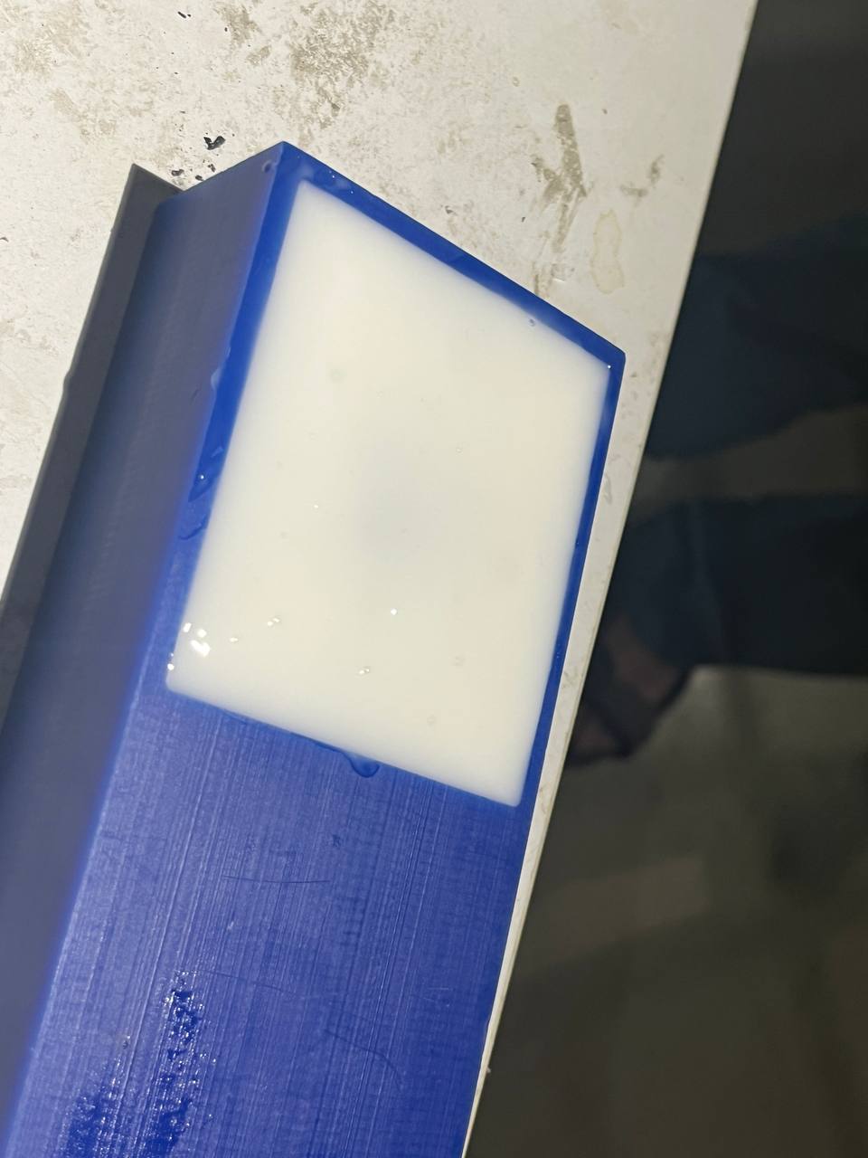
Finally poured the silicone into the positive wax mold
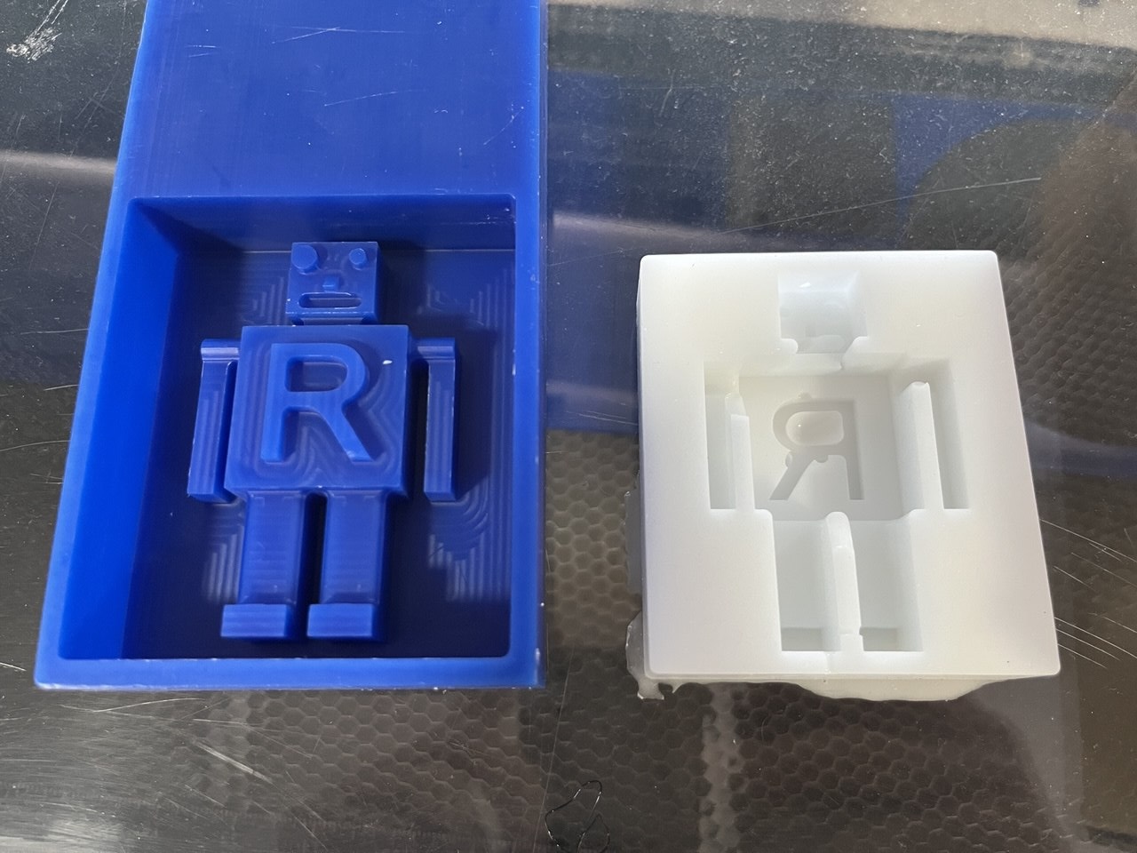
Here's the wax mold filled, and then removed the next morning:
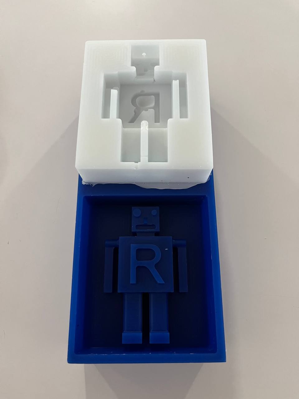
The produced negative mold is not perfect. There are several small areas where the silicone did not sufficiently settle in, particularly in some small areas like the mouth, between the legs, and around the letter 'R'. This happened because the silicone-compund mixture is quite thick and doesn't easily settle into very small places.
Casting the figure
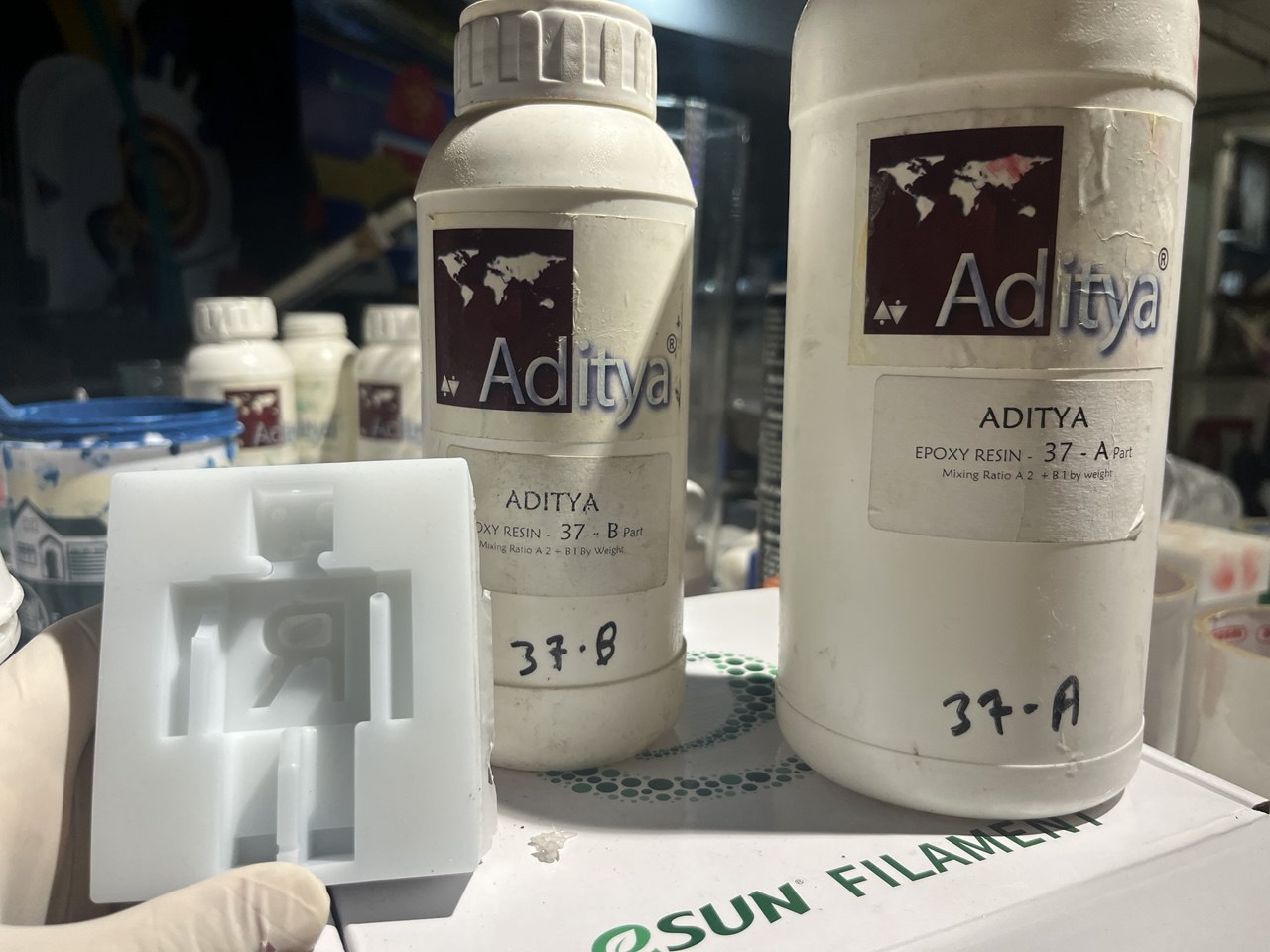
At long last, it is time to cast the robot figure. We will mix parts A and B of an "Ultra Clear Cast Epoxy" also available from Aditya company.
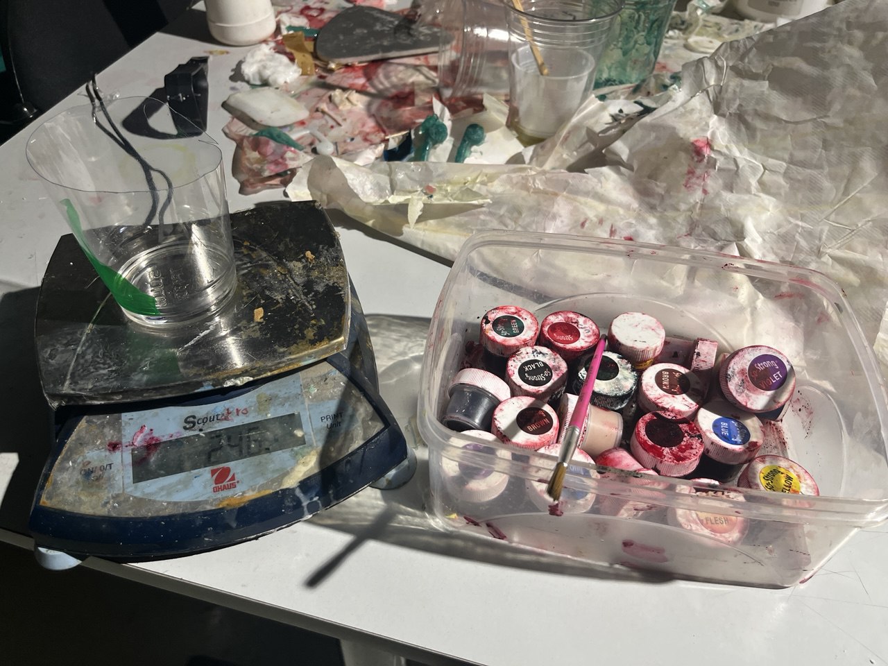
Again we use a scale to take the appropriate relative proportion. And added a very small amount of red colour dye from Smooth-On.
Finally, in the afternoon we set the coloured resin into the mold, but we neglected to use a mold release spray.
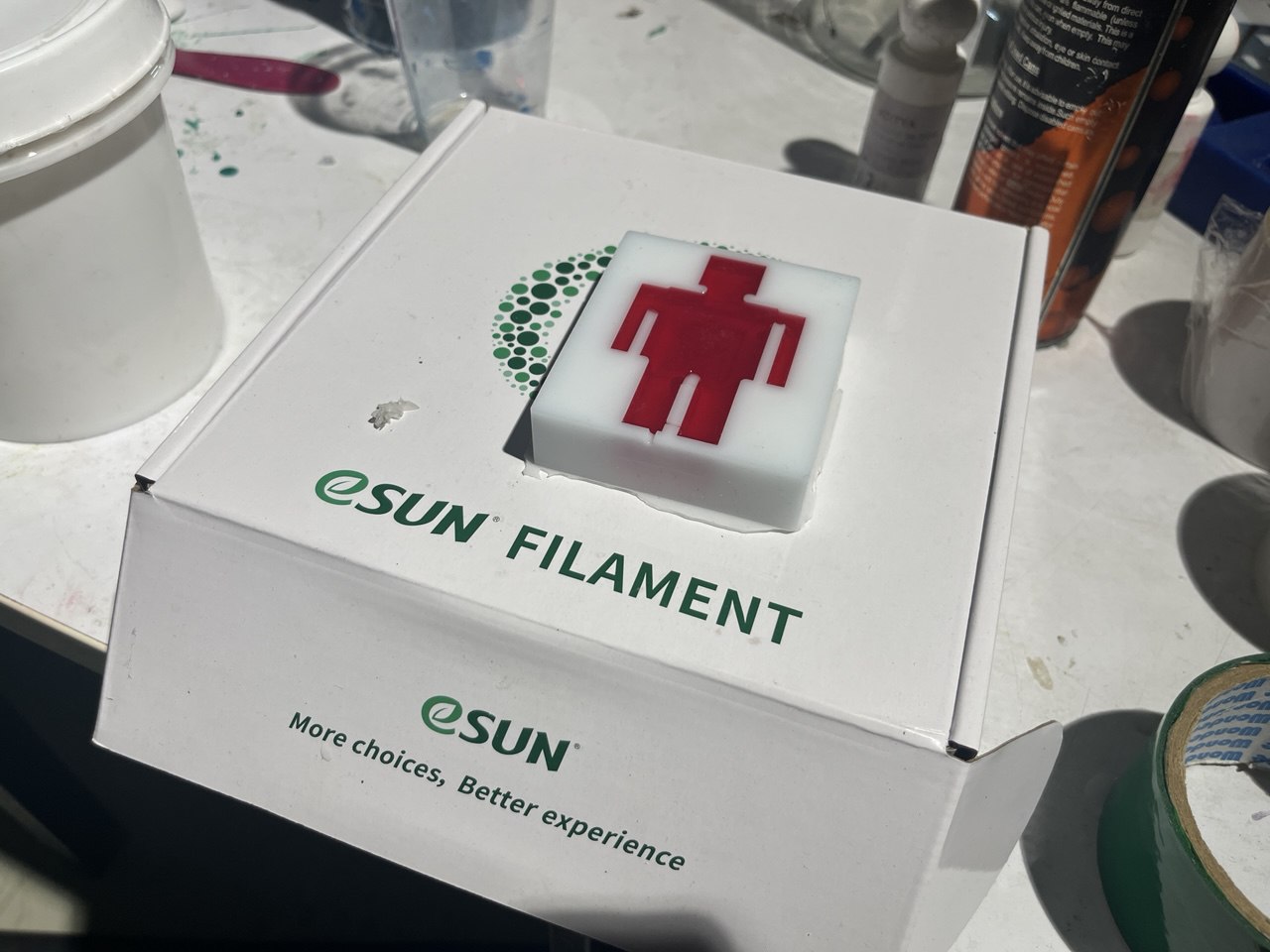
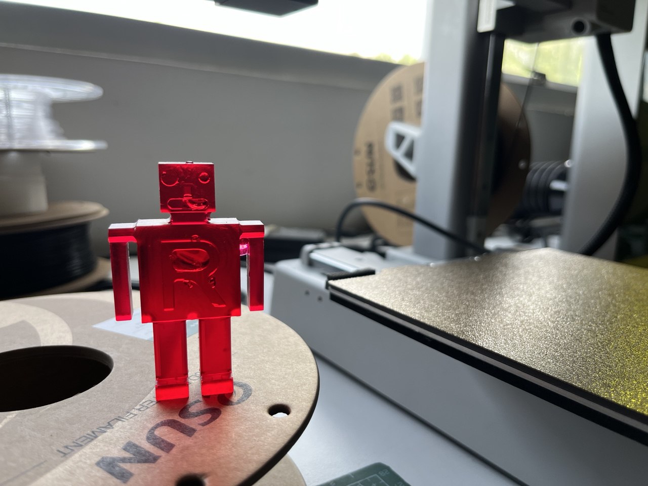
The following morning at about 10 am, excitedly entered the lab and with some small difficulty released the figure from its mold. Thus it had cured for 16 hours. Look at the result, ma sha Allah!:
Design Files
Design in Fusion (.f3d)Tools library for Fusion
Machining Files (.gcd)