Week 11: Networking & Communications
Group Assignment: send a message between two projects
Individual Assignment: design, build, and connect wired or wireless node(s) with network or bus addresses and local input &/or output device(s)
Communication Methods
UART / Asynchronous
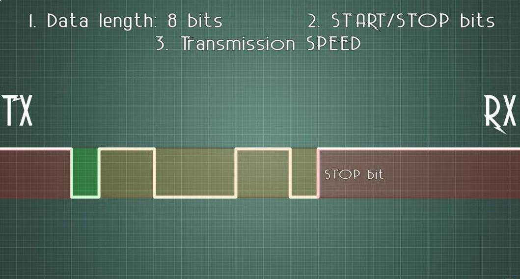
UART stands for Universal Asynchronous Receiver Transmitter. It is a wired method of communication, a key point is it is Asynchronous which means the data sent is not monitored or coordinated by a clock. Instead, there is a pre-existing agreement about the 1) data length, 2) start/stop bits, and 3) speed of transmission. This allows for the data to be transferred with precision. Image credit.
For communicating between multiple devices using UART we can employ "hop-counting" or "broad-hopping". Basically these are methods to count the devices in the network, give them addresses, as well as communicate with them. Here is a screenshot of the concept from Dr. Neil's previous lecture illustrating the concept. Image credit.
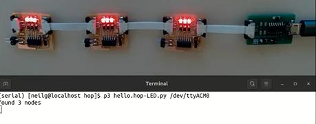
Its a little difficult to understand precisely how it is all working, but important to try. Anyway, this section is about Asynchronous communication which again means that it is not coordinated by a clock. Instead the line is held on high, and at any time a device in the network may start transmitting.
I2C / Synchronous
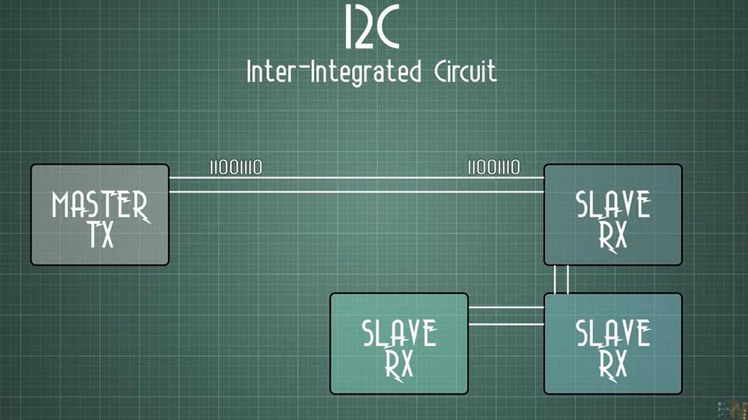
In contrast, I2C and other types of synchronous communication use time when transmitting. For I2C in particular, there are 2 lines, namely SDA (Serial Data) and SCL (Serial Clock), and they work in conjunction. Image credit.
SPI - Serial Peripheral Interface
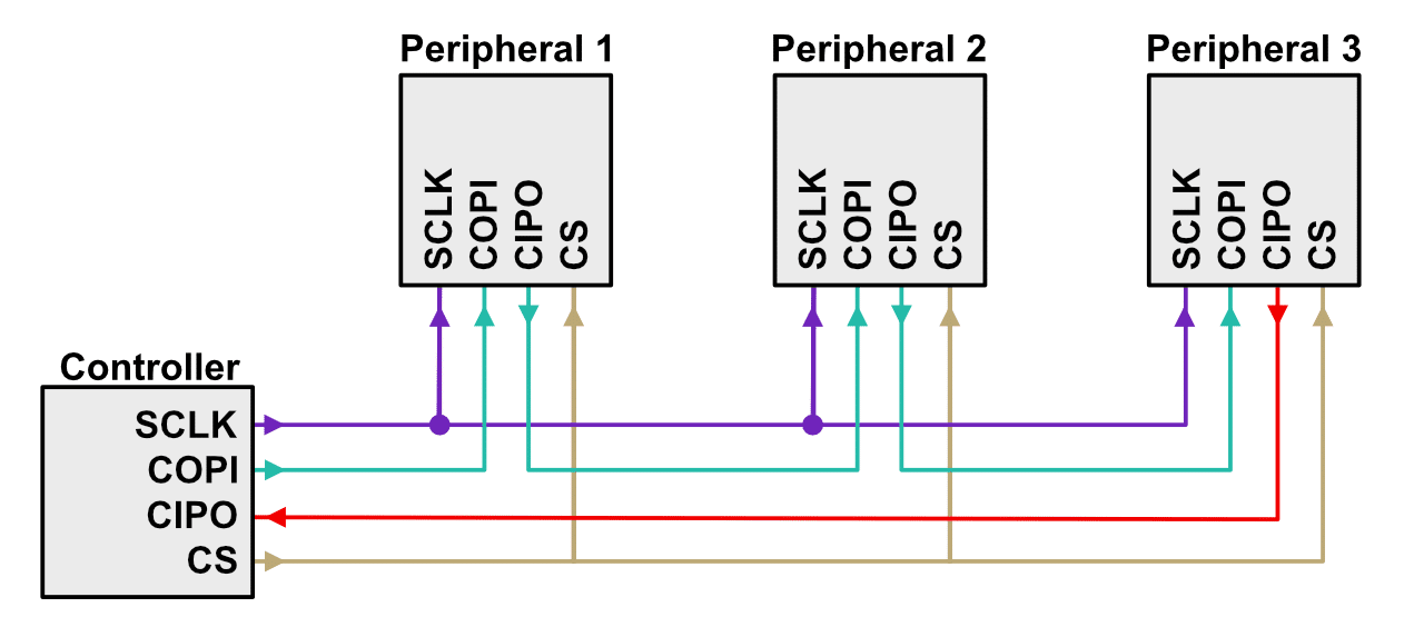
SPI is another major communication protocol. It uses 4 pins to communicate with another device, and then usually requires an additional pin for each additional device connected. However it is fast and in some aspects easier, because it has a dedicated line for both sending and receiving between the master and slave. Image credit.
Communication!
Set-Up:
We have to make more NEMA boards since in this week we need to communicate to multiple devices.
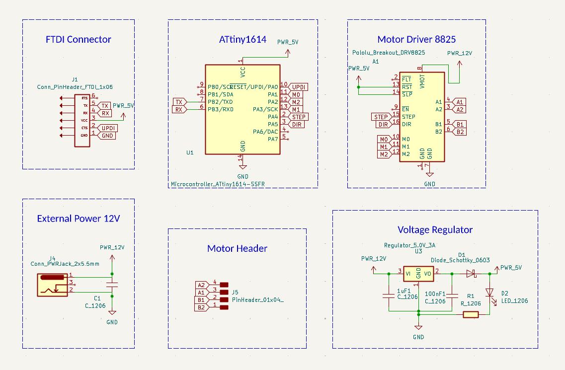
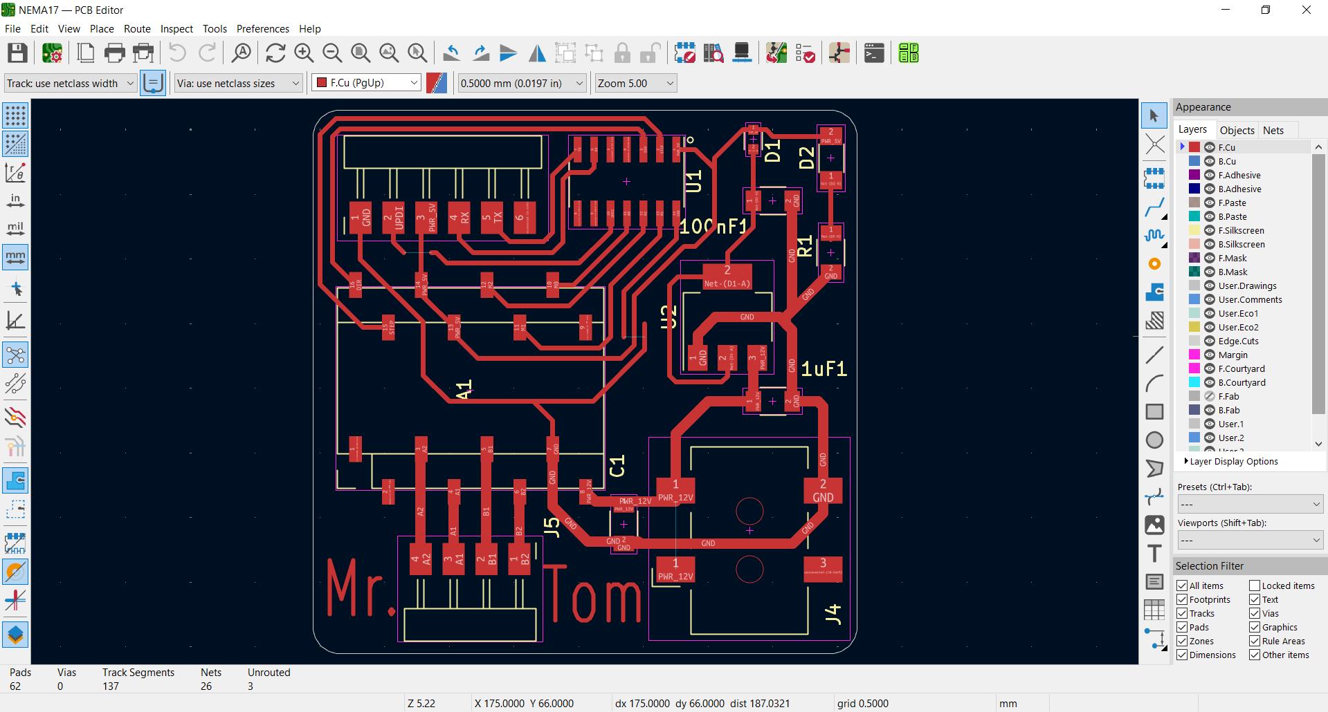
We already successfully designed the board with the following schematic and PCB layout last week, so all further details on the design with associated documentation will be found there.
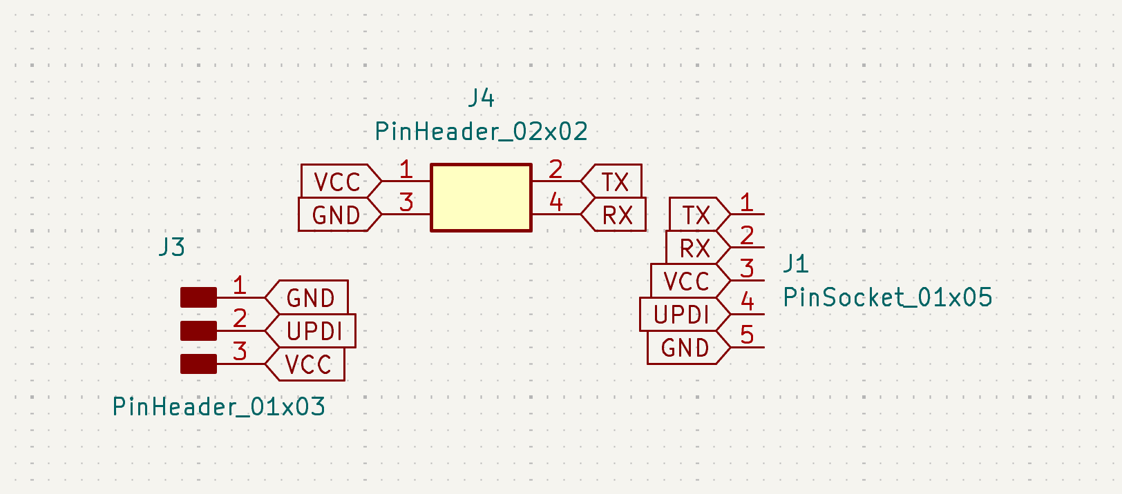
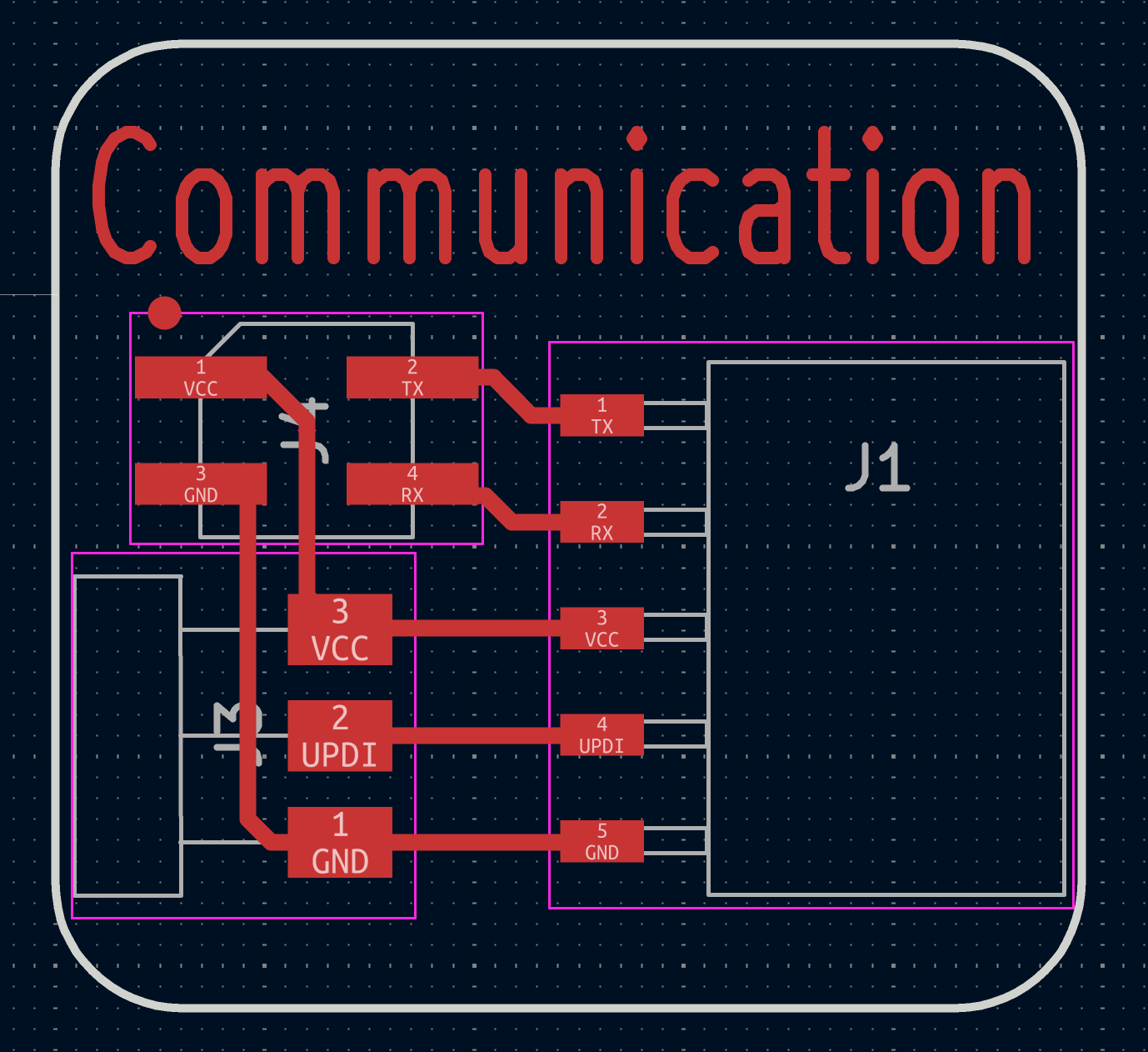
The task this week is to communicate. Saheen explains one possibility is through supplemental connector boards. The plan is to communicate with UART, so this additional mini-board will have the RX TX pins. We will also be able to program through the programmer via this board.
First step is to design such board. We did; here is the schematic and then PCB design for it:
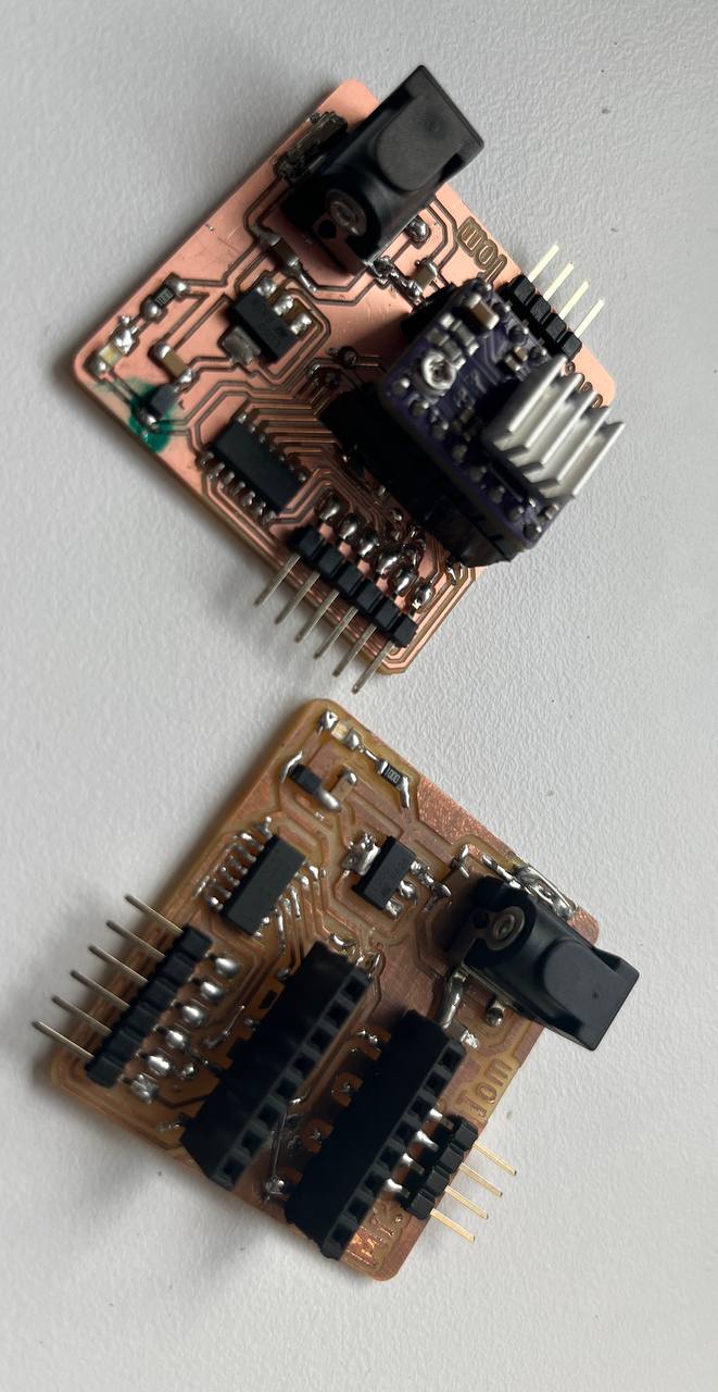
We cut the mini-boards using the X-Tool laser machine. It was good practice to review that.
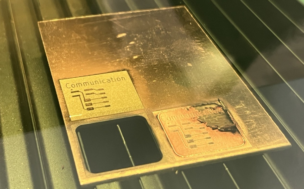
Also it was weirdly enjoyable to clean these boards with the toothbrush.

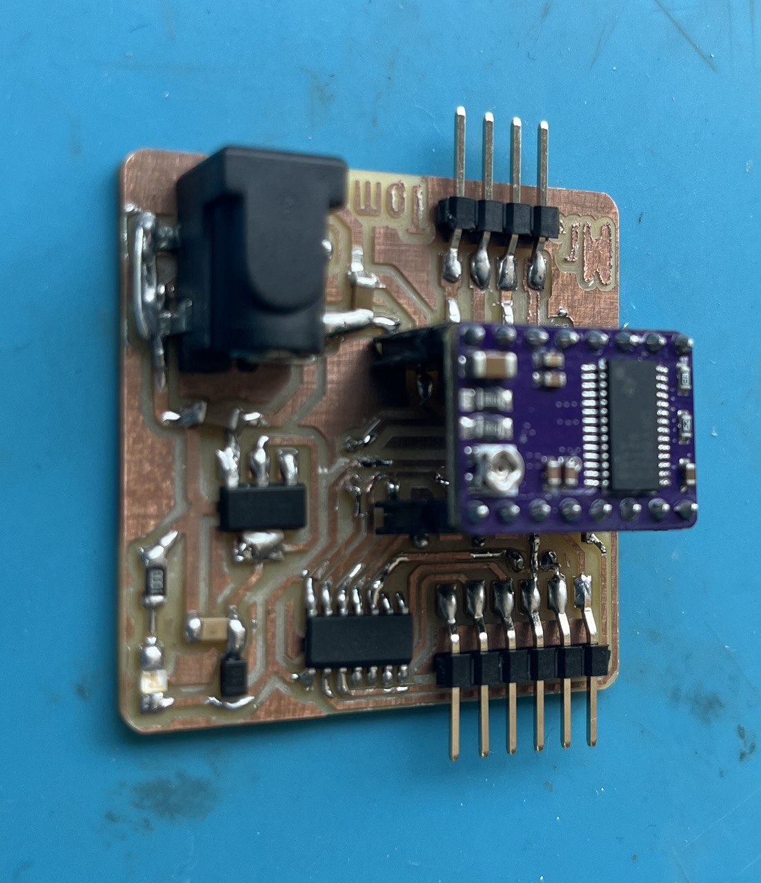
Connected the two motor boards with wires to the mother-board. The mother-board is the same that we designed in week 6 and produced in week 8.
Programmming:
Now its all about programming. Actually 2 programs, as we'll need a program both for the RP2040 Master and the two motor controllers driven by ATtiny1614. What we'll do is adapt programs from the previous weeks. We will also enlist the help of our favorite AI, perplexity. transcript.
Master Program: in week 8, "Electronics Production", we created a simple board with a button and some LEDs controled by the RP2040. This is our master board, and what follows is the main part of the program. Our task is to control both the selection of external motors (Motor 'A' / Motor 'B'), as well as the status of those motors. We can control all of this from a single button by differentiating between short and long presses. The long press will toggle between motors, and the short press will toggle between modes on the selected motor. Hence in the main loop we are detection button press, button release, as well as measuring the time between these events.
int red = 28;
int green = 27;
int blue = 26;
int led = 2;
int button = 3;
int count = 0;
bool currentBS; // button state
bool previousBS = HIGH; // for edge detection
bool blueOn = false;
bool redOn = false;
char motor = 'A';
unsigned long pressStartTime = 0;
bool isLongPressHandled = false;
enum ShortPressState {OFF, LEFT, RIGHT};
ShortPressState shortPressState = OFF;
//#define CMD_SWITCH_MOTOR 0x10
//#define CMD_CYCLE_STATE 0x20
void setup() {
Serial1.begin(57600); // Start UART on Serial1 at 57600 baud
pinMode(button, INPUT_PULLUP);
pinMode(red, OUTPUT);
pinMode(green, OUTPUT);
pinMode(blue, OUTPUT);
pinMode(led, OUTPUT);
turnOffAllLEDs();
}
void loop() {
currentBS = digitalRead(button); // 0=pressed, 1=not pressed
// Detect button press (falling edge)
if (previousBS == HIGH && currentBS == LOW) {
pressStartTime = millis();
isLongPressHandled = false;
}
// Detect button release (rising edge)
if (previousBS == LOW && currentBS == HIGH) {
unsigned long pressDuration = millis() - pressStartTime;
if (!isLongPressHandled) {
if (pressDuration < 500) {
handleShortPress();
}
}
}
// Long press detection while button held
if (currentBS == LOW && !isLongPressHandled) {
unsigned long pressDuration = millis() - pressStartTime;
if (pressDuration >= 1000) {
handleLongPress();
if (motor=='A'){
turnOnBlue();
motor='B';
}
else{
turnOnRed();
motor='A';
}
isLongPressHandled = true;
}
}
previousBS = currentBS;
delay(10);
}
void handleShortPress() {
Serial1.print(motor);
Serial.print(motor);
if (shortPressState == OFF) {
digitalWrite(green, LOW);
shortPressState = RIGHT;
}
else if (shortPressState == RIGHT) {
Serial1.print('R');
Serial.print('R');
shortPressState = LEFT;
}
else {
Serial1.print('L');
Serial.print('L');
shortPressState = OFF;
}
}
void handleLongPress() {
switcheroo();
digitalWrite(led, LOW);
shortPressState = OFF;
}
void switcheroo() {
if (redOn) {
turnOnBlue();
} else if (blueOn) {
turnOnRed();
}
}
void turnOffAllLEDs() {
digitalWrite(red, HIGH);
digitalWrite(green, HIGH);
digitalWrite(blue, HIGH);
}
void turnOnBlue() {
redOn = false;
turnOffAllLEDs();
digitalWrite(blue, LOW);
blueOn = true;
}
void turnOnRed() {
blueOn = false;
turnOffAllLEDs();
digitalWrite(red, LOW);
redOn = true;
}
Node Programs: the node programs are developed from our NEMA programs from week 10. Actually relatively few changes are needed here, and very few changes between the two programs for the two boards with connected motors in this project. In particular, note that in line 21 of the following code for the second motor: if (motor == 'B' || motor == 'b'). Hence the motor for board B will only work if port B is specified by the program in the master board, and likewise for board A.
const int dirPin = 1; // DIR pin connected to digital pin 1
const int stepPin = 0; // STEP pin connected to digital pin 0
enum MotorState { STOP, TURN_RIGHT, TURN_LEFT };
MotorState currentState = STOP;
void setup() {
Serial.begin(57600); // Initialize serial communication at 9600 baud
pinMode(dirPin, OUTPUT); // Set direction pin as output
pinMode(stepPin, OUTPUT); // Set step pin as output
}
void loop() {
while (Serial.available() == 0) { // Wait for user input
delay(10); // Small delay to avoid busy waiting
}
char motor = Serial.read();
char direction = Serial.read();
if (motor == 'B' || motor == 'b') {
if (direction == 'R' || direction == 'r') {
Serial.println("Motor B turning Right!");
right();
} else if (direction == 'L' || direction == 'l') {
Serial.println("Motor B turning Left!");
left();
} else {
Serial.println("Invalid direction. Use R or L.");
}
} else {
Serial.println("Invalid motor. Use A or B.");
}
}
void right() {
// Set direction to clockwise
digitalWrite(dirPin, HIGH);
Serial.println("Clockwise");
for (int i = 0; i < 200; i++) {
digitalWrite(stepPin, HIGH);
delayMicroseconds(1000); // 1 ms delay
digitalWrite(stepPin, LOW);
delayMicroseconds(1000); // 1 ms delay
}
}
void left() {
// Set direction to clockwise
digitalWrite(dirPin, LOW);
Serial.println("Counter-Clockwise");
for (int i = 0; i < 200; i++) {
digitalWrite(stepPin, HIGH);
delayMicroseconds(1000); // 1 ms delay
digitalWrite(stepPin, LOW);
delayMicroseconds(1000); // 1 ms delay
}
}
Now please watch the video and kindly observe that the controls for the attached second motor only work when the second motor is activated, indicated by the blue LED. Hence the long press does indeed allow us to toggle between and select the motors, and the subsequent small pushes control the motor activity.
Group Assignment Reflection
This week's group assignment was led by Ashish and Ancy; they did an amazing job! The project involved communication via ESP-NOW between Ashish's board with an RFID card reader, and Ancy's boards. The concept was that a particular card with UID could be scanned, and each of the cards would send a signal to different boards.
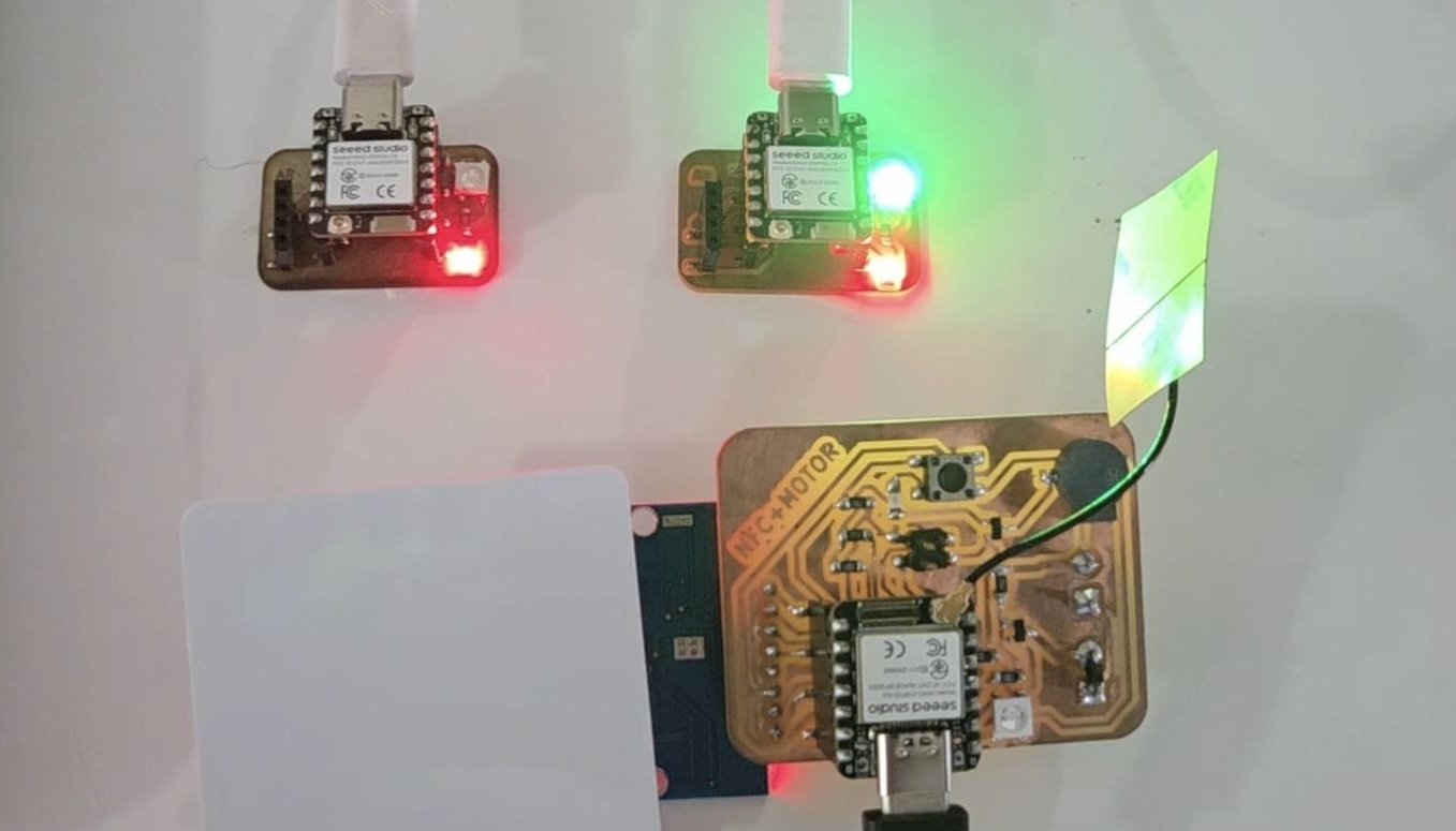
Actually ESP-NOW and other communication methods are quite new and very interesting, including LoRa (Low Range) modules. Wired and wireless communication is a huge and deep field of study. The group assignment and this week generally helped to appreciate that.
Files:
Communication Board - KiCad filesCommunication Board - Gerber files
Master Program
Slave B Program