Week 6: Electronics Design
Group Assignment (link): use the test equipment in your lab to observe the operation of a microcontroller circuit board.
Individual Assignment: use an EDA tool to design an embedded microcontroller system using parts from the inventory, checking its design rules for fabrication, and simulating its operation. Extra credit: try different languages &/or development environments.
Group Assignment Reflection:
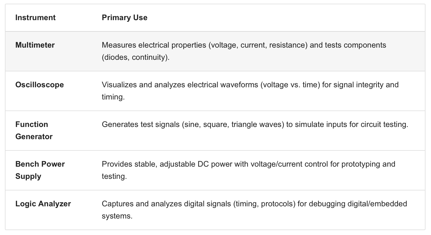
Actually I never had the chance to use the basic tools like Multimeter and Oscilloscope, but in the group assignment we were able to learn together about the different tools. For example with the multimeter we learned the basic functions like continuity test, measuring voltage, and determining resistance. For the Oscilloscope we learned that it displays the voltage over time. The following table presents a list of the tools we covered and their functions.
KiCad 9.0 - Getting Started
We will use a progam called KiCad, recommended by Dr. Neil, and available at www.kicad.org. Download and install.
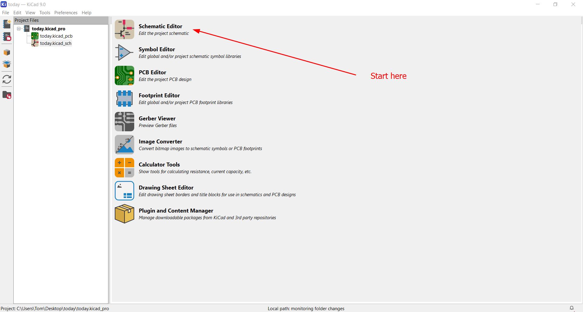
It has different programs and functionalities; we will use schematic editor to start.
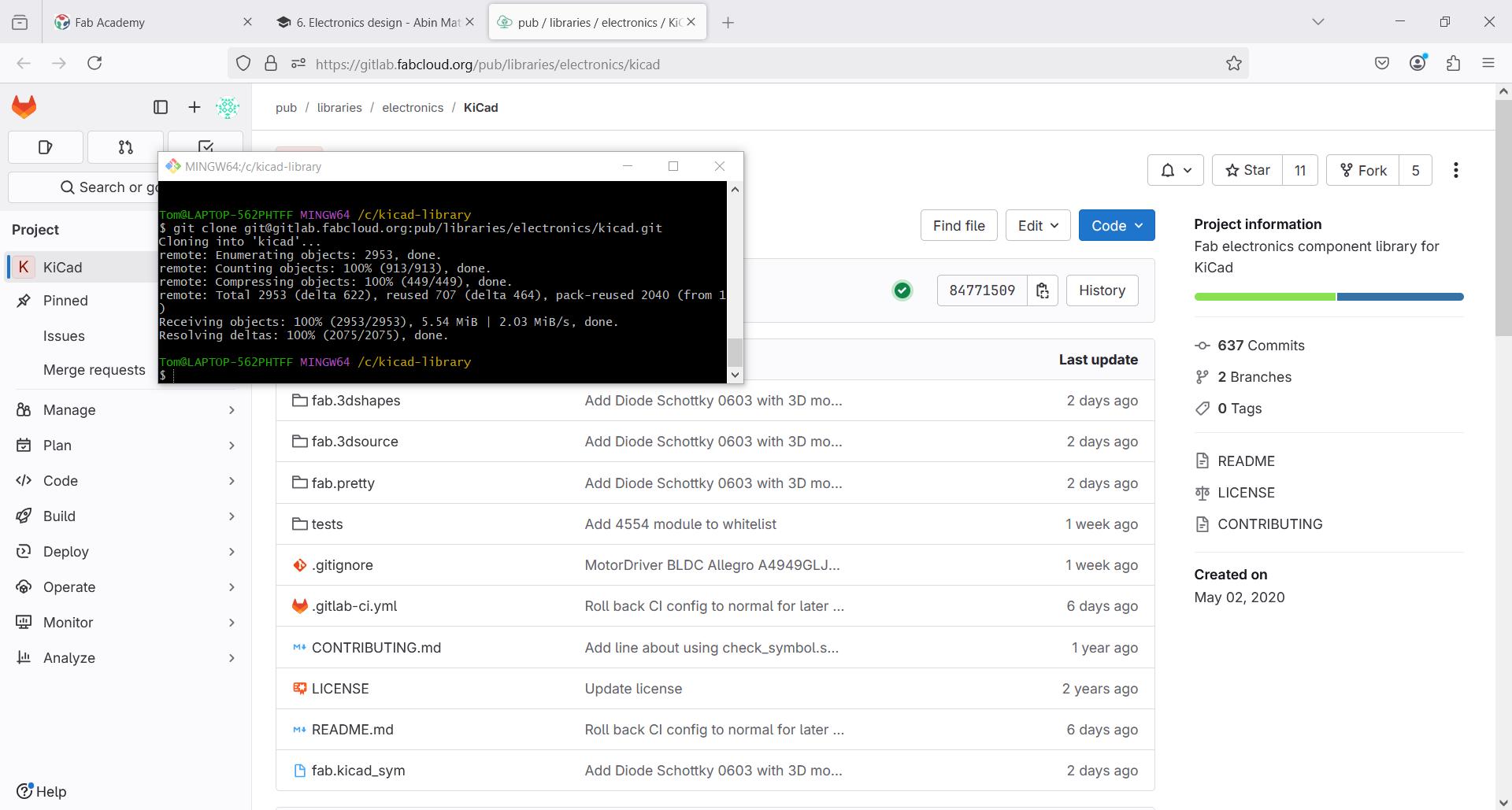
But first we needed to find a 'fab' library of parts here, and clone it using 'git'.
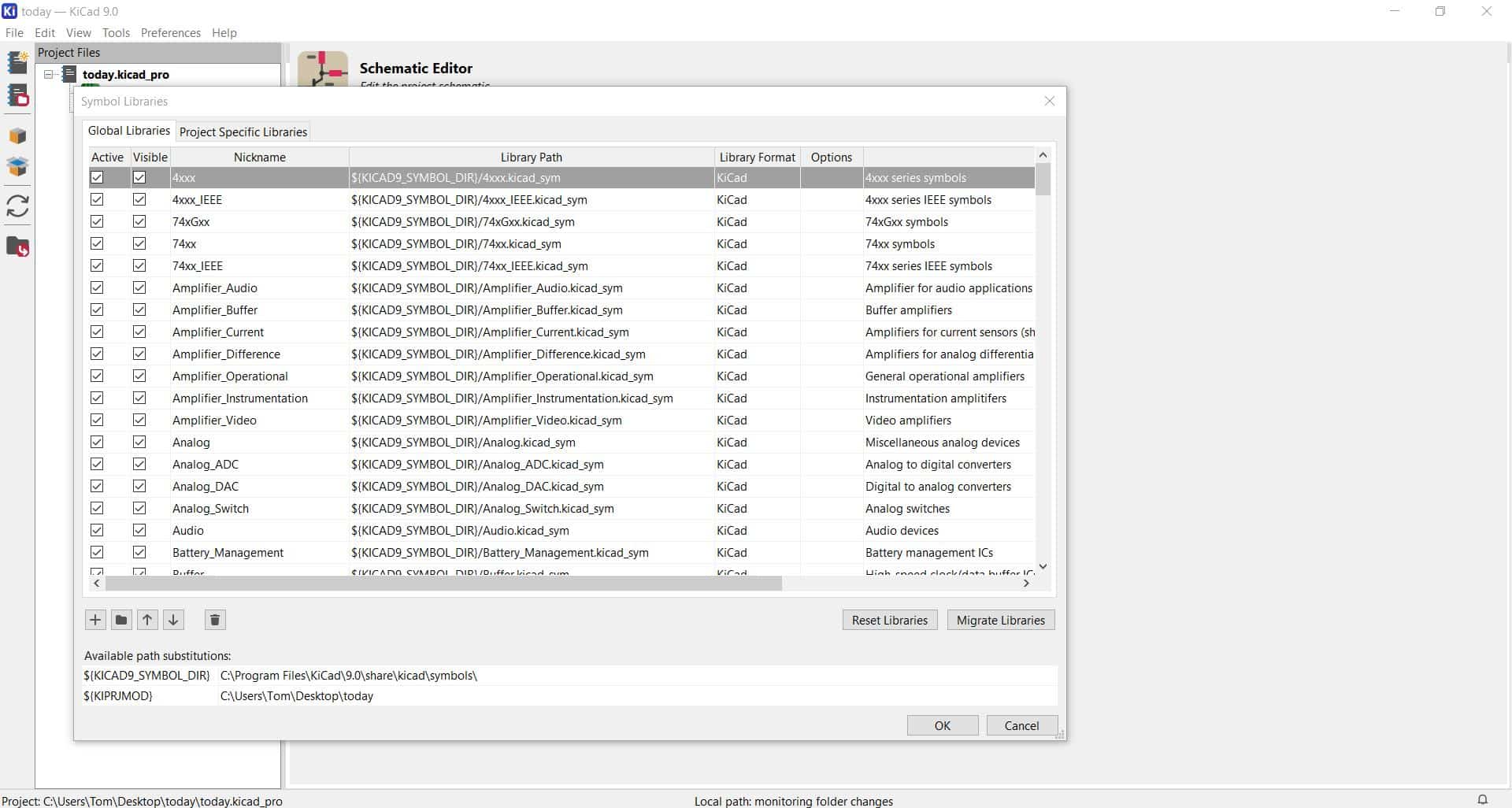
Then we needed to import it to KiCad, from preferences tab, both the parts and footprint.
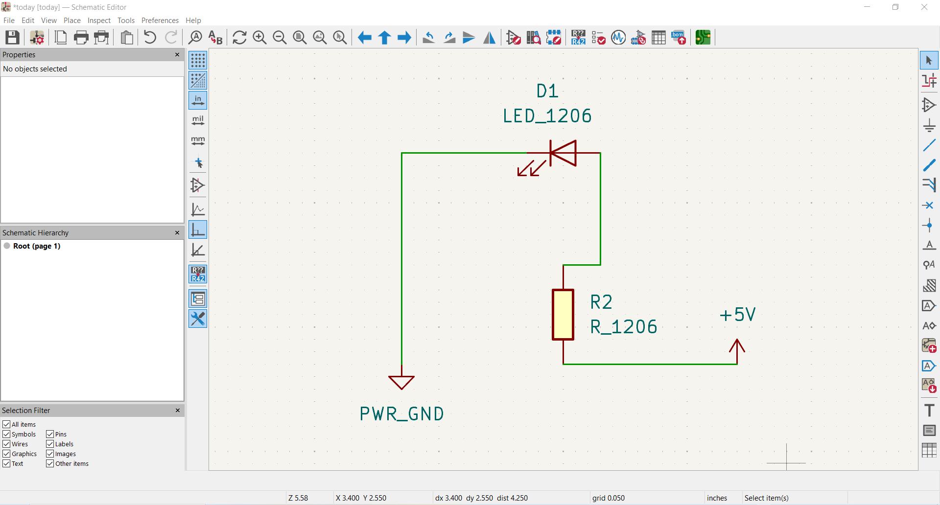
Now we can start making circuits. This is the first example for LED
We find the list of components to include with the 'A' shortcut, and we may rotate with 'R' shortcut.
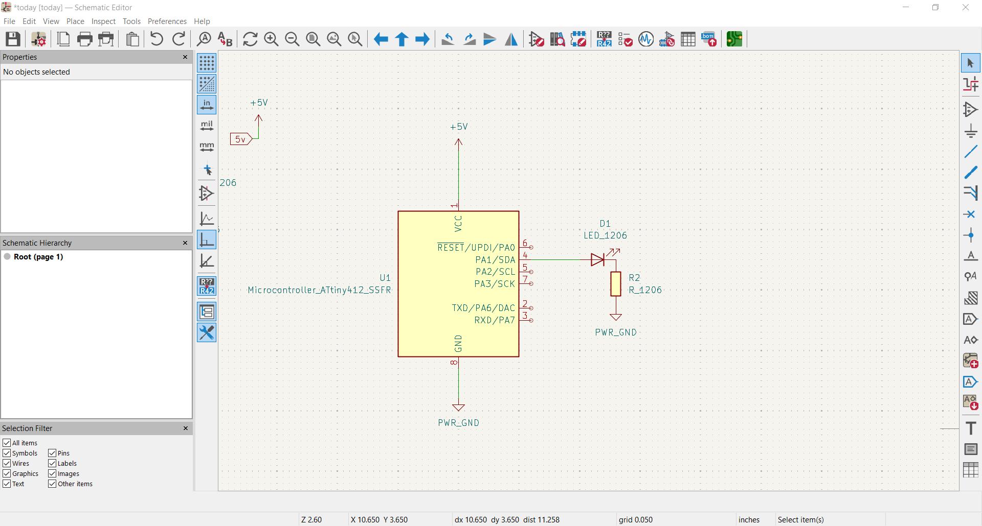
KiCad 9.0 - ATTINY412 Microcontroller
Now that we are set up in KiCad, we add a microcontroller (ATtiny412) and connect LED. This is an example project we are using for training.
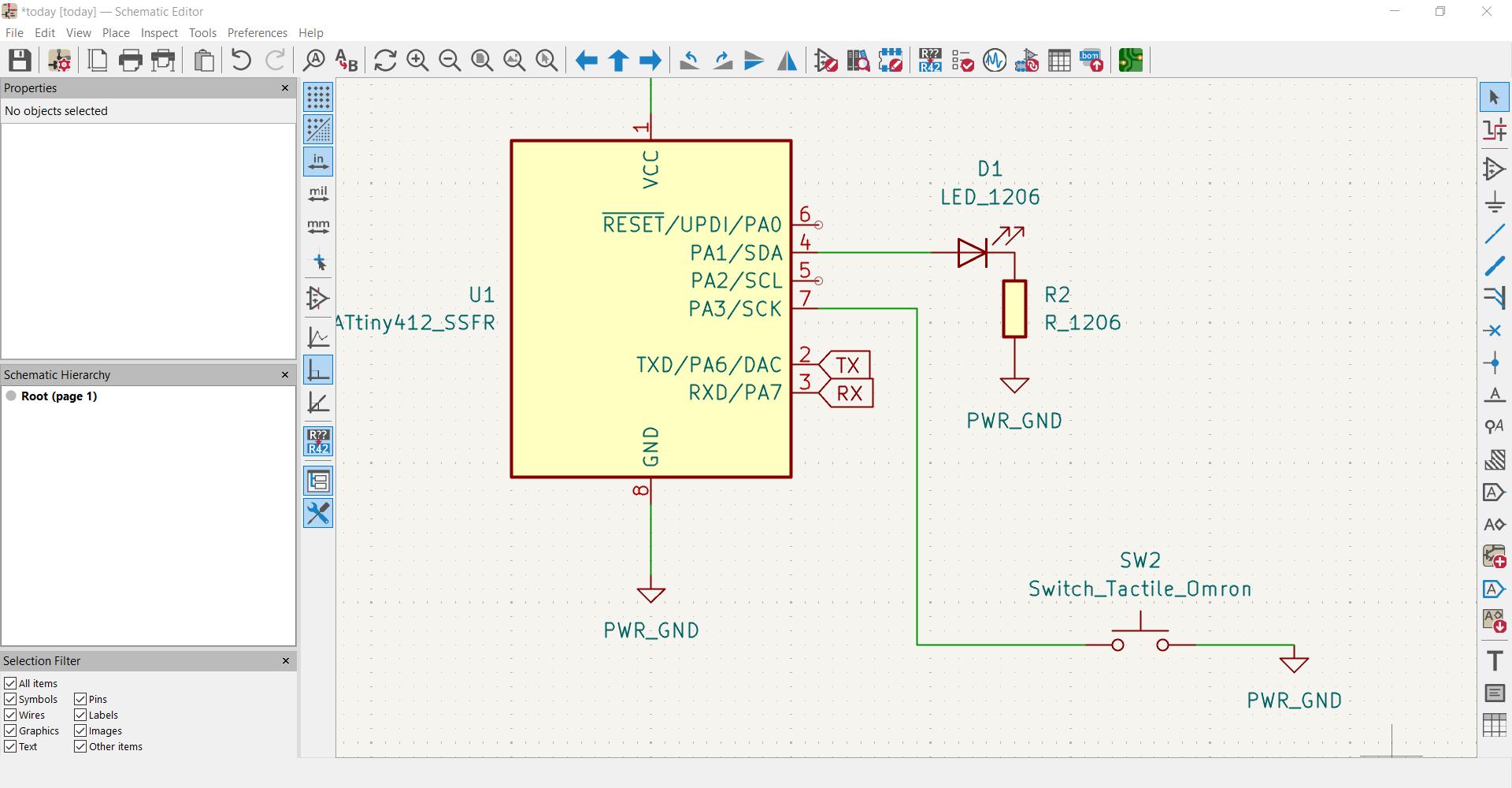
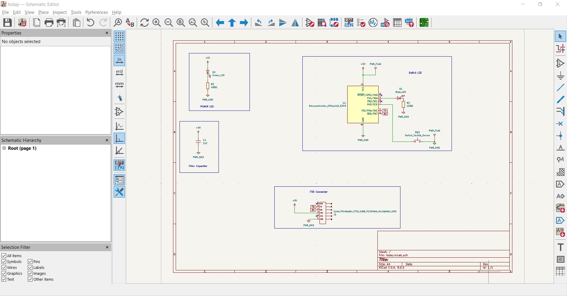
Now also added a switch. Additionally learning about labels, for example here "RX" and "TX"
Here we have added power flags to the power source and ground.
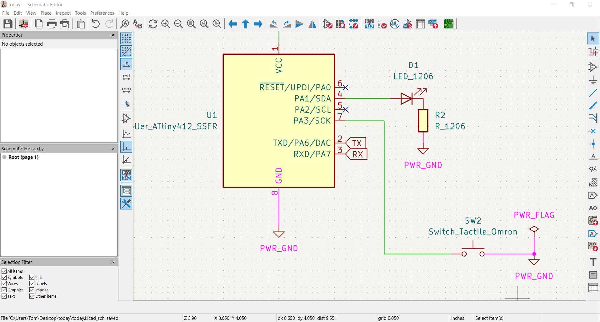
Here's the final schematic:
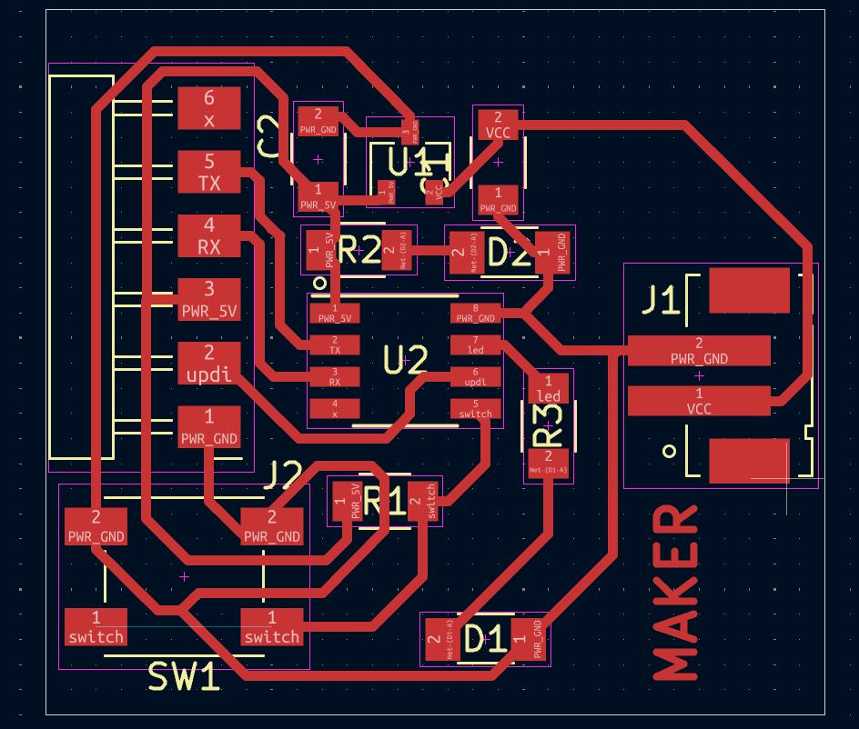
Sadly, I was out of the country when the class went through this example, so I had to catch up and anyway, wasn't there to go through the whole process. Fortunately, however, some members of this cohort produced excellent documentation, such as Ashish, from whom I have taken the following image of the final PCB using the ATtiny412.
PCB Design for XIAO RP2040 - Schematic, PCB Editor, & ERC
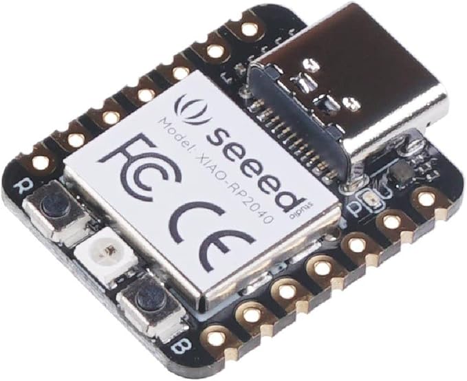
We actually have this Seeed Studio microcontroller and will use it on a real board of our design. Refer back to week 4 for the pin diagram. Image credit.
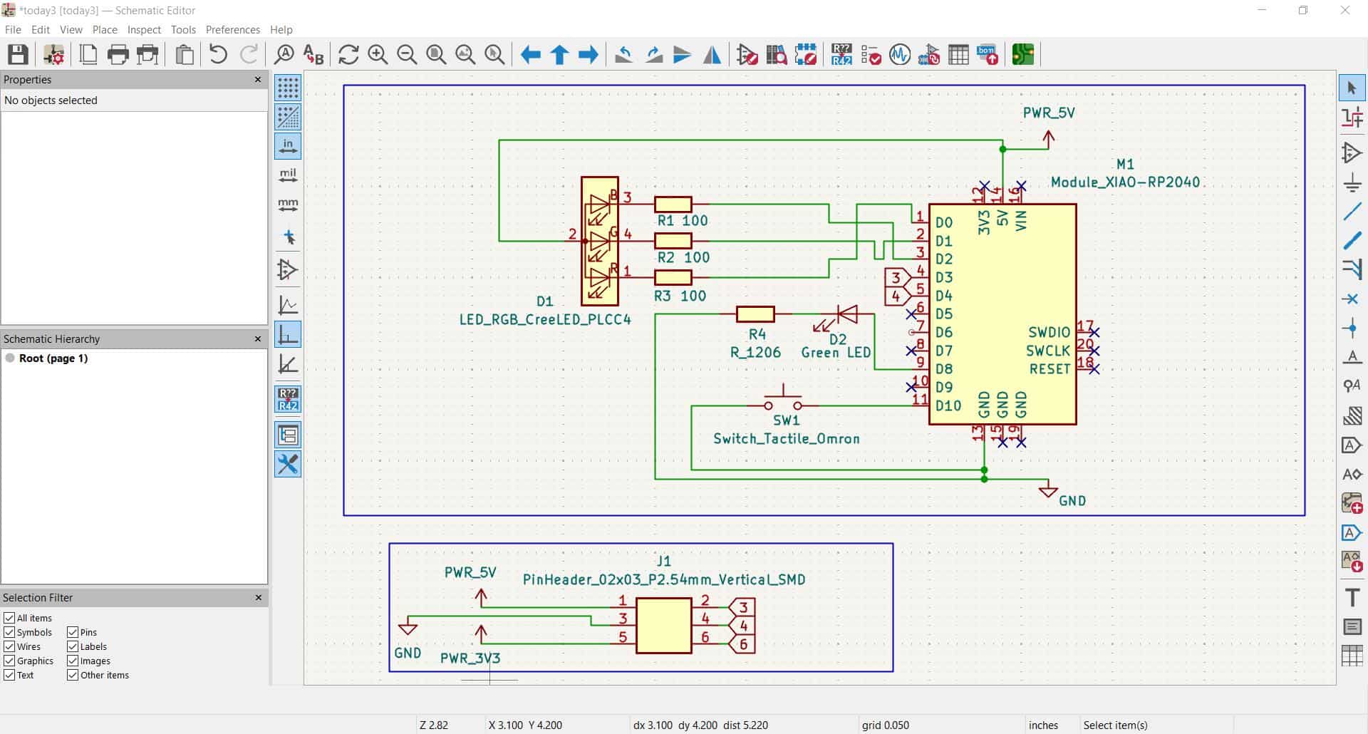
After significant trial, error and frustration in which I considered quitting the academy, here is the simplified schematic, including a header (insisted upon by Saheen) so we can later place I/O devices.
Once the schematic is finished, we may open it as shown in the PCB editor. Look at the placement of connectors and traces (created by toggling 'X' shortcut).
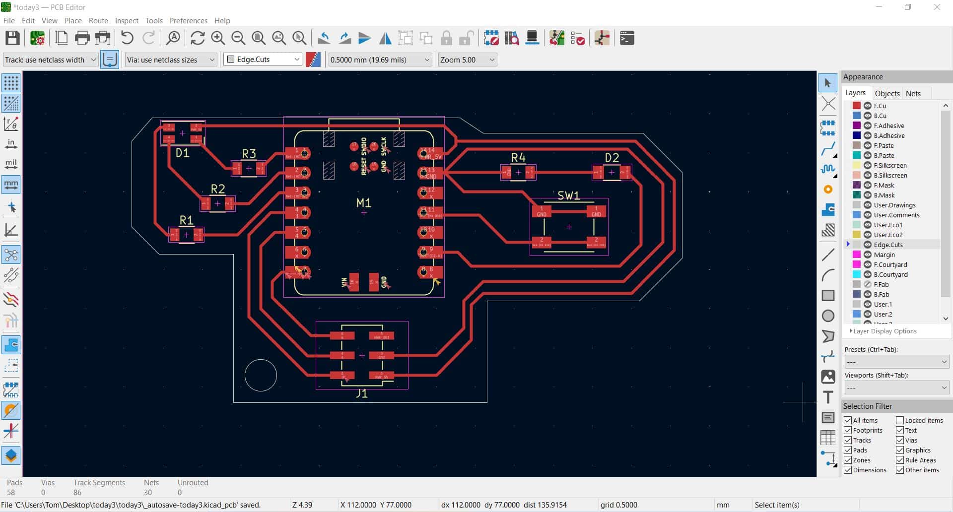
Our design passes the ERC (Electrical Rule Check), which will let us create this in our lab after a few weeks.
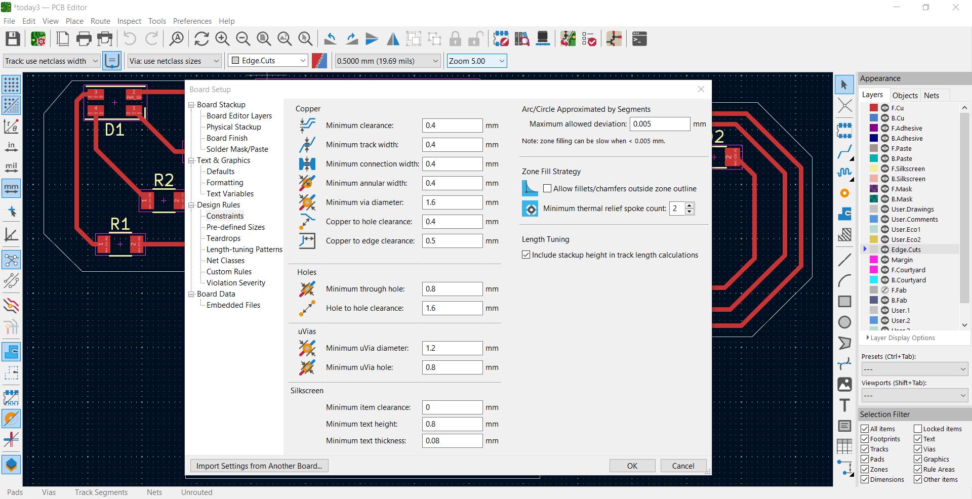
For reference, design rules can be found (and edited) under "File"->"Board Setup..."
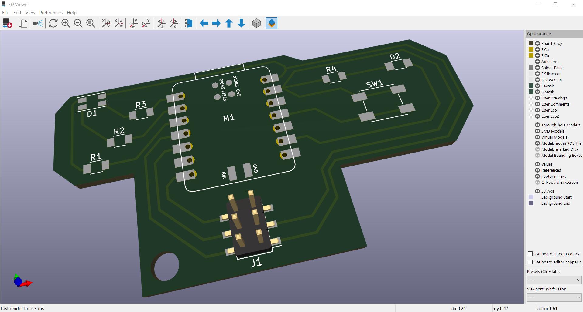
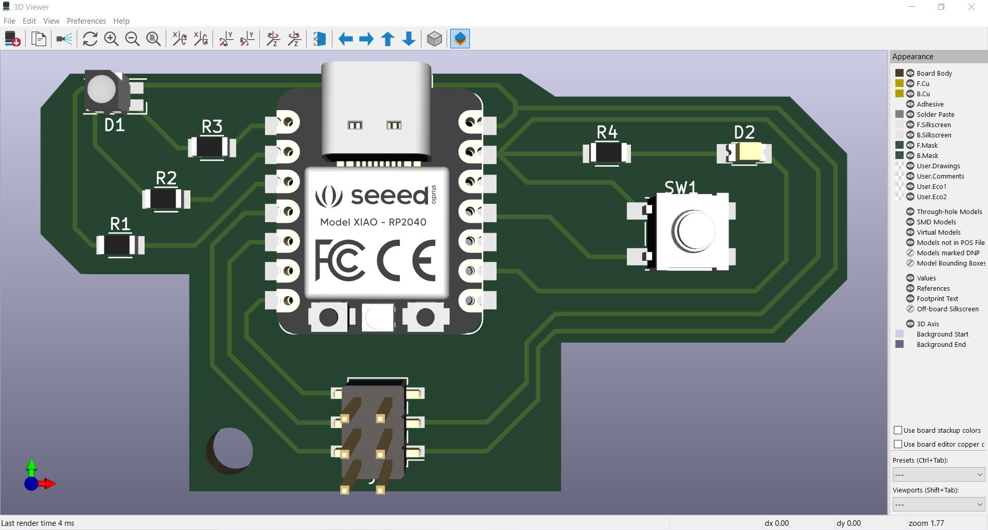
PCB Design for XIAO RP2040 - 3D Viewer & Placing the Components
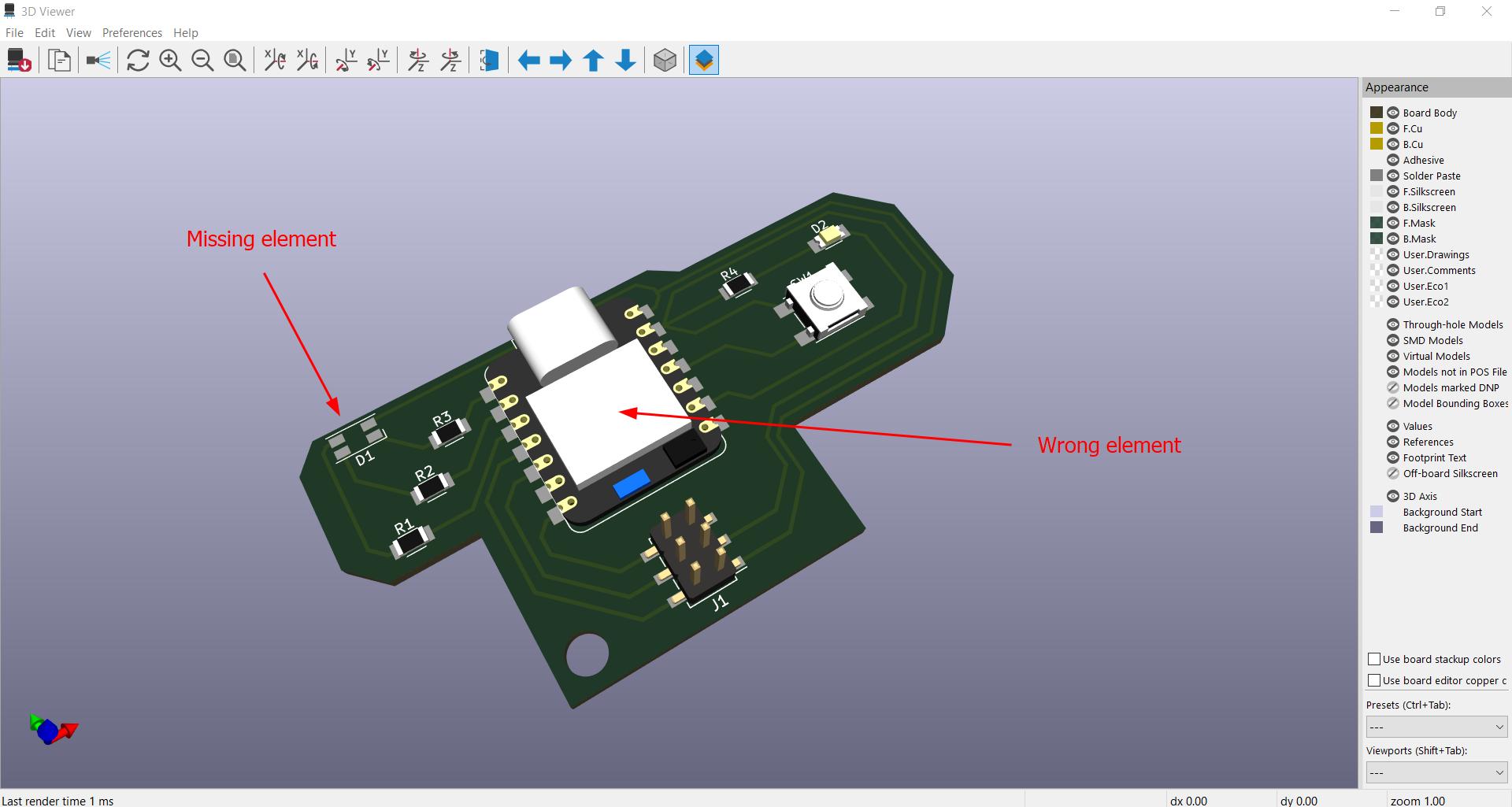
Finally, here is the 3D Viewer. But wait, the components aren't there!
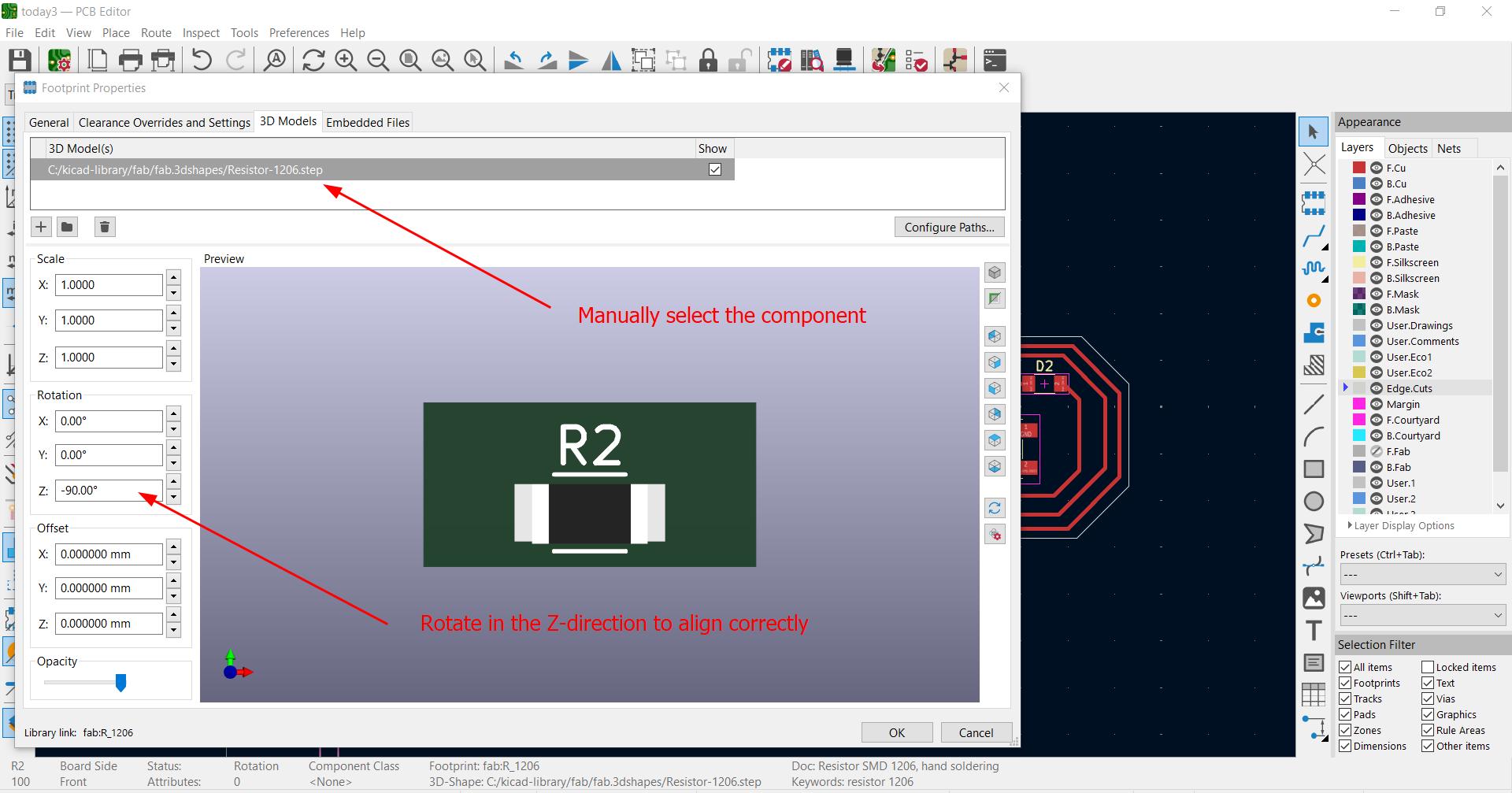
Placing the components to generate the full 3D model is very nice; to start the process, in the PCB editor, double click the component (or right click and select properties) and find the component, being sure to rotate correctly.
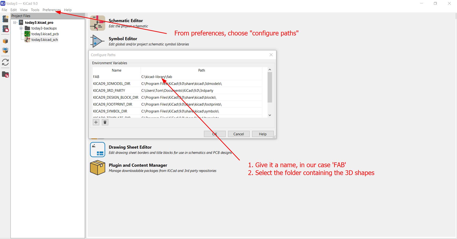
We can also configure path to connect the 3D models automatically and include the component.
However, this automatic process doesn't always work perfectly as not all components in the FAB library contain an associated 3D model.
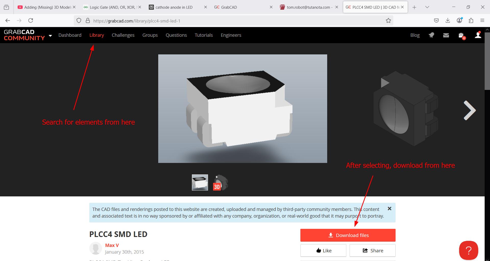
To solve this issue we formed an account on GrabCAD to download those particular models - the RGB LED and XIAO RP2040 board.
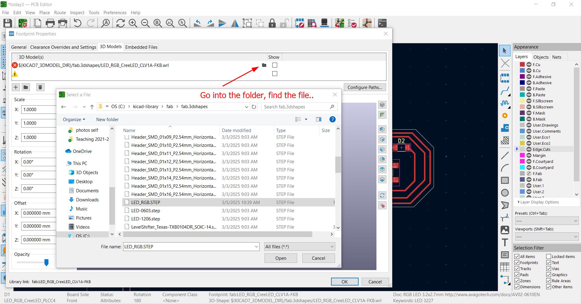
For each we then manually selected it from the library after double-clicking on the component.
HERO SHOT! Check this beautiful rendering! Overall I'm pretty satisfied with the design: there are enough components but not too many and there is sufficient space to solder with relative ease. I like that I added a hole (bottom-left): it will go on a necklace or keychain to take it with me everywhere. Excited to produce it soon...
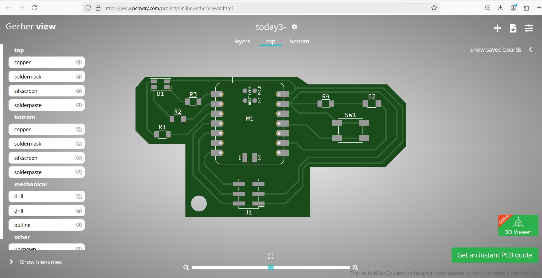
PCB / XIAO RP2040 - Gerber and Design Files
Finally to note that we may use the board file here to create a gerber file.
Gerber files are 2D vector file which specifies the locations of the traces and edges of
the board. This is the type of file needed to produce our PCB in the future.
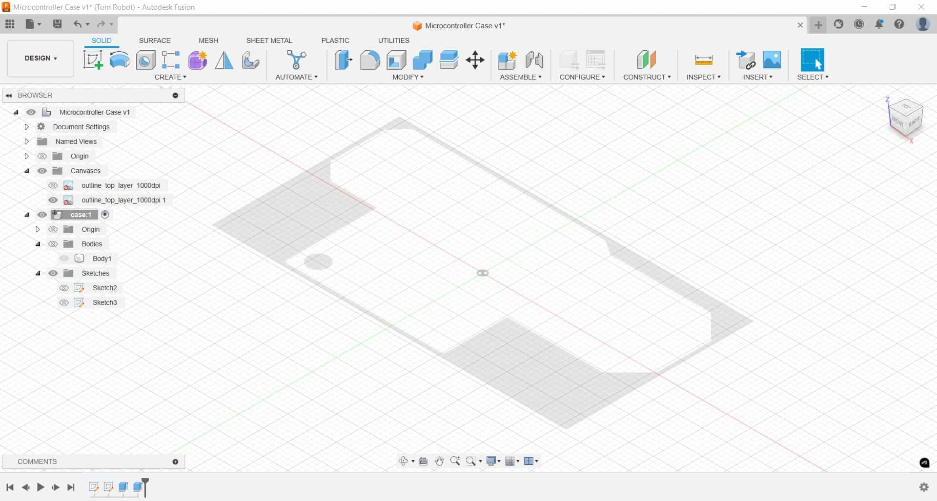
Design for PCB case
Other superstars of the Fab Academy, such as Namita, were designing 3D printed cases for their boards. Seems like a great idea.
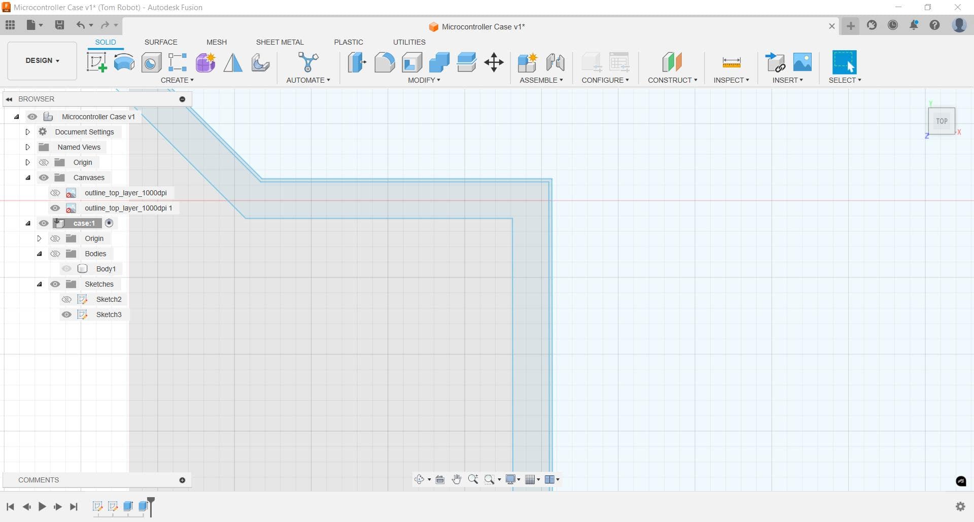
I started by importing the layout of my PCB and created a sketch from it:
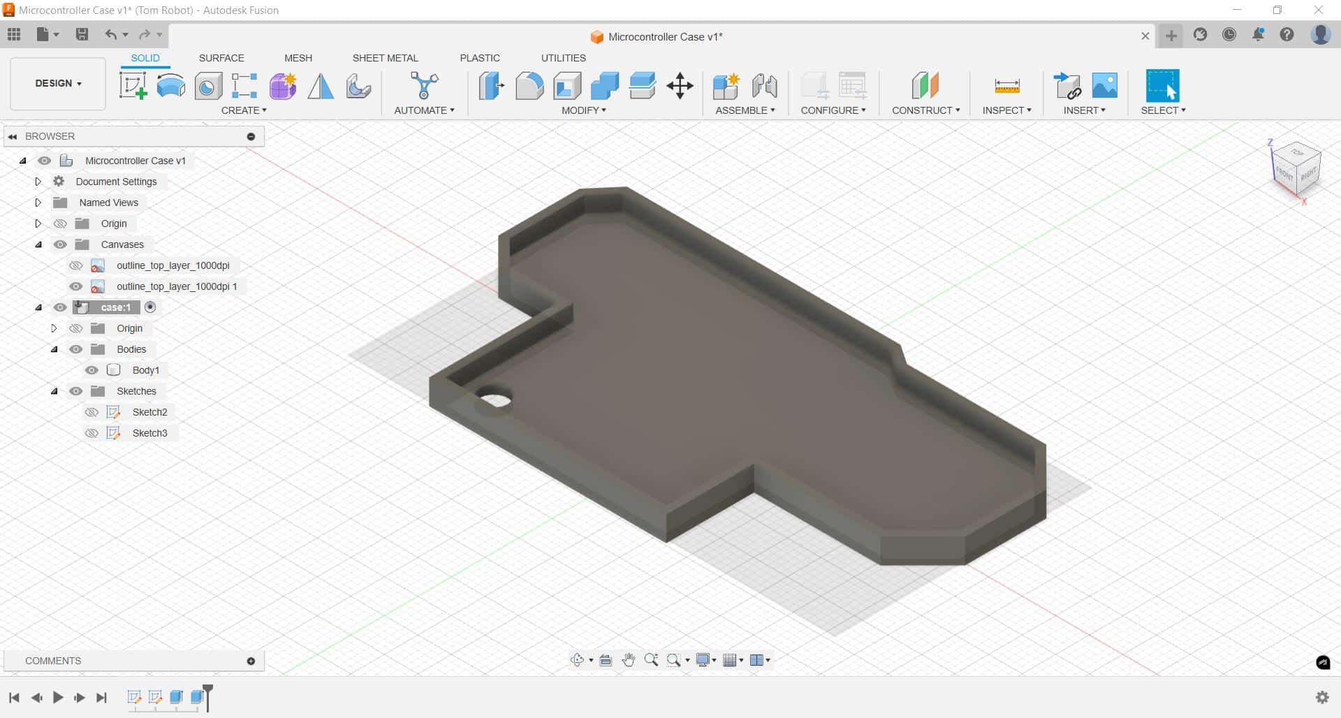
Next, we offset the edges of the board:
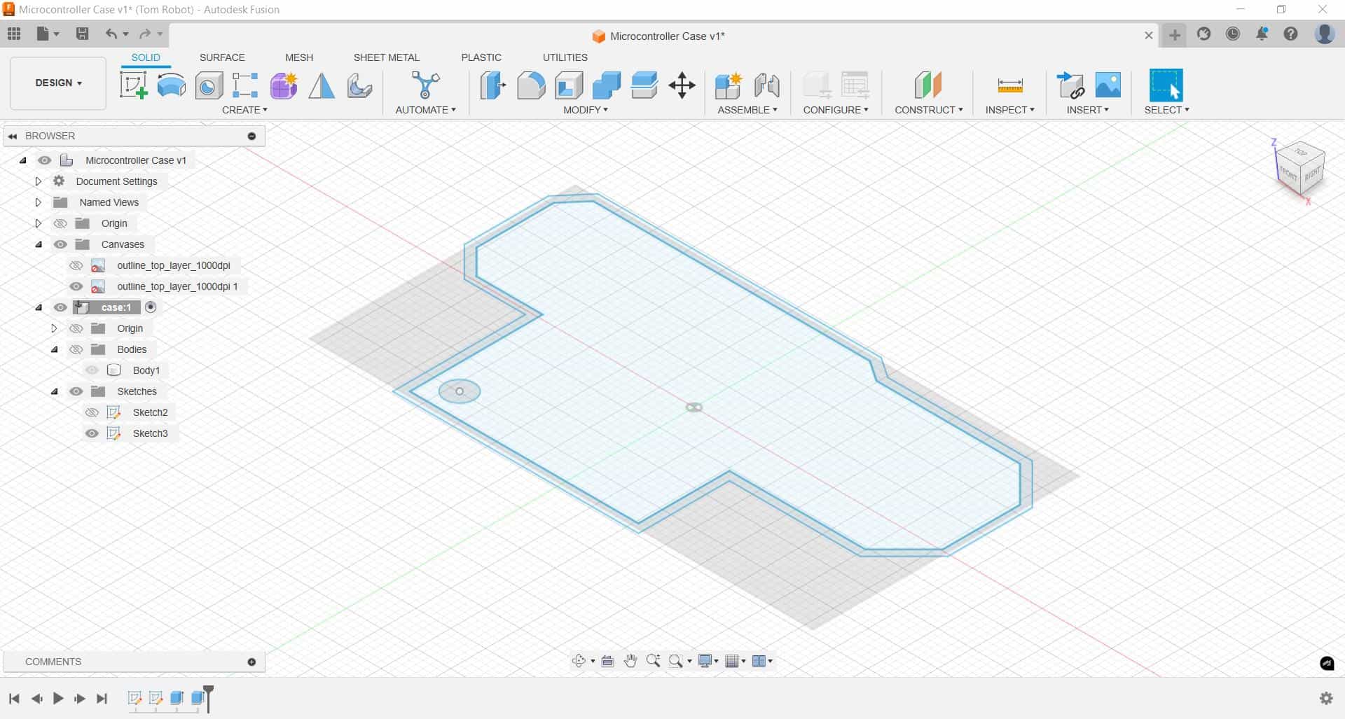
Actually offset twice, once by 0.1 mm so the board would have space to fit, and again by 1.3 mm which will be the thickness of the case.
Finally we extruded to get the final shape. Very nice!
Addendum: some insights on Electronics
Actually I don't have a background in electronics. I mean like zero. Except for playing with Arduino years ago. So here are some things I learned:
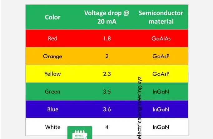
1. LEDs consume different voltage:
Wallahi I thought that LEDs would take the same voltage, but some require more as seen in this table. Anyway, the amount an LED requires or consumes is called the 'Forward Voltage' and as a result, the Blue LED for example, which has higher voltage consumption, can be used with a smaller level resistor. Whereas a LED requiring less voltage, like the Red LED, should have a higher level resistor.
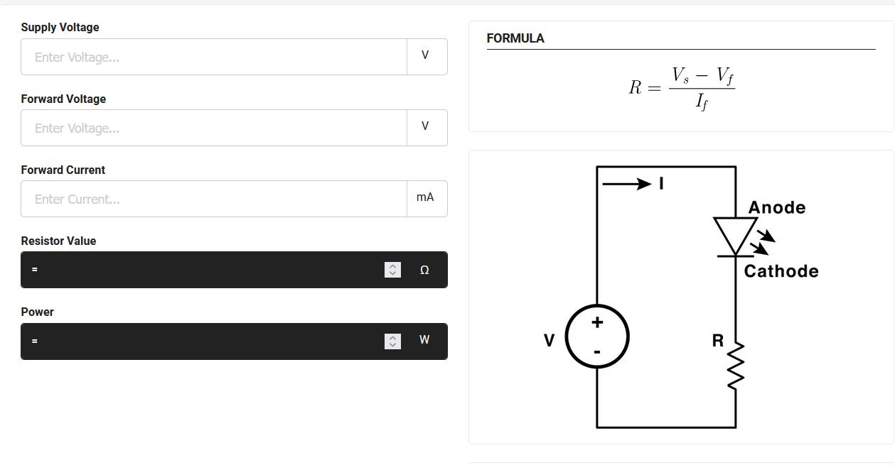
2. Calculator for V=IR: Of course the famous Ohm's law equations which link Voltage with Current and Resistance... Well sometimes we want to calculate that quickly and easily. There is online calculator here at digikey.in:
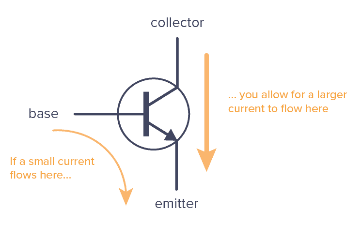
3. Transistors: Actually I never knew what was transistor, which is a shame... One tutorial put it on level with FIRE in terms of its importance in all of human history! Basically we may consider it analagous to a switch. The switch when pressed allows the flow of electricity in a circuit.. Similarly a transistor can allow the flow of electricity in a circuit by providing a small amount of voltage.
4. Logic Gates: logic gates and transistors together allow computing: This video blew my mind
Design Files:
Board - KiCad Files
Board - Gerber Files
Board - Step File
Case (Fusion)