Week 4: Embedded Programming
Group Assignment (link): compare workflows for available embedded architectures
Individual Assignment: 1) browse through the data sheet for a microcontroller; 2) write and test a program for an embedded system using a microcontroller to interact and communicate; 3) extra credit: try different languages &/or development environments.
RP2040 DataSheet
The RP2040 Datasheet gives full information about the RP2040 Microcontroller. Find it here.
Here's information about the name "RP2040"
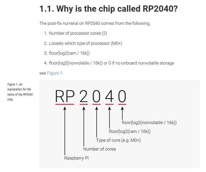
Here's a detailed overview of the chip:
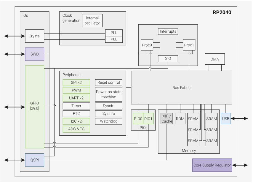
Many things here I don't know what they are, for example:
- SWD - communication protocol for bootloader etc
- QSPI - communication protocol for flash devices
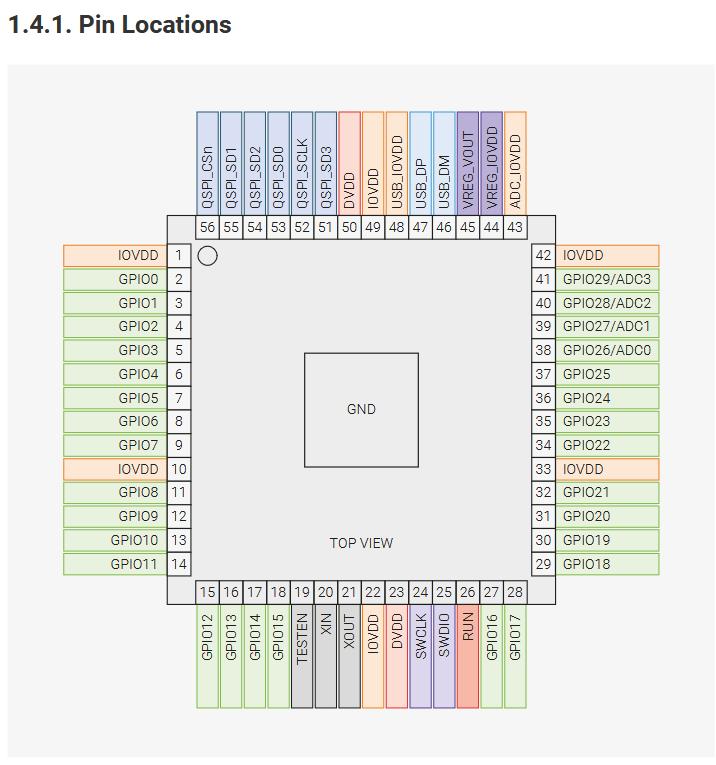
Here's the pinout of the RP2040. Note that specific development boards can use more or less of the pins.
The Xiao-RP2040 has fewer GPIO than the Raspberry Pi Pico, though they both use the same Microcontroller!
In summary the chip, the microcontroller is amazing. So much packed into such small size. I'm learning a lot.
Some additional questions worth asking:
- What's the chip? Answer: RP2040 has a dual M0+ processor cores.
- what speed? Answer: the ARM cortex microprocessor has speed 133 MHz
- What flash / SRAM memory? Answer: External flash memory and 264kB of embedded SRAM in 6 banks
- How many GPIO pins? How many analog pins? Answer: Total 30 GPIO pins, 4 Analog pins
- What communication protocols? Answer: Yes, many.
- Does it have an ADC? Answer: Yes it has an analog to digital converter.
Programming SEED RP2040 with Thonny:
Thonny is a Python IDE. Search for, download and install that is easy at: thonny.org. As a group in Kochi we read and followed this documentation, which was extremely helpful. We made some simple programs like the following, mainly using the 3 little built-in LEDs.
# import few functions from their respective libraries
from time import sleep
from machine import Pin
# define the colours specified by their pin numbers
Blue=Pin(25,Pin.OUT)
Red=Pin(17,Pin.OUT)
Green=Pin(16,Pin.OUT)
Colours=[Blue,Red,Green]
# main function blinking the light
def allblink():
for colour in Colours:
colour.low()
sleep(0.3)
colour.high()
sleep(0.3)
# loop over the main blinking function
while True:
allblink()
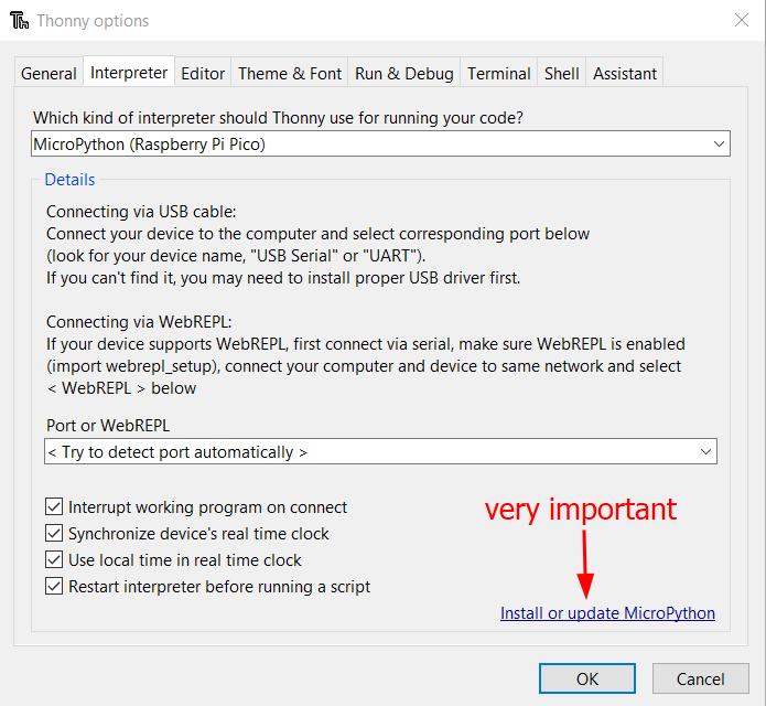
There were some difficulties, most important to note is that the MicroPython interpreter needs to be installed on the RP2040. You will need to do it again if the same microcontroller is used with Arduino code, since it compiles and sends there hex code.
To do this, navigate to "Run"->"Configure interpreter" and you'll see the following dialogue. You may need to hold the boot button on the board for your computer to recognize the device, but after it does, you'll select "Pico / Pico H" from the dropdown and just say "Okay".
However, we were successful to download and run the program as can be seen:
Programming simulated Arduino (WOKWI):
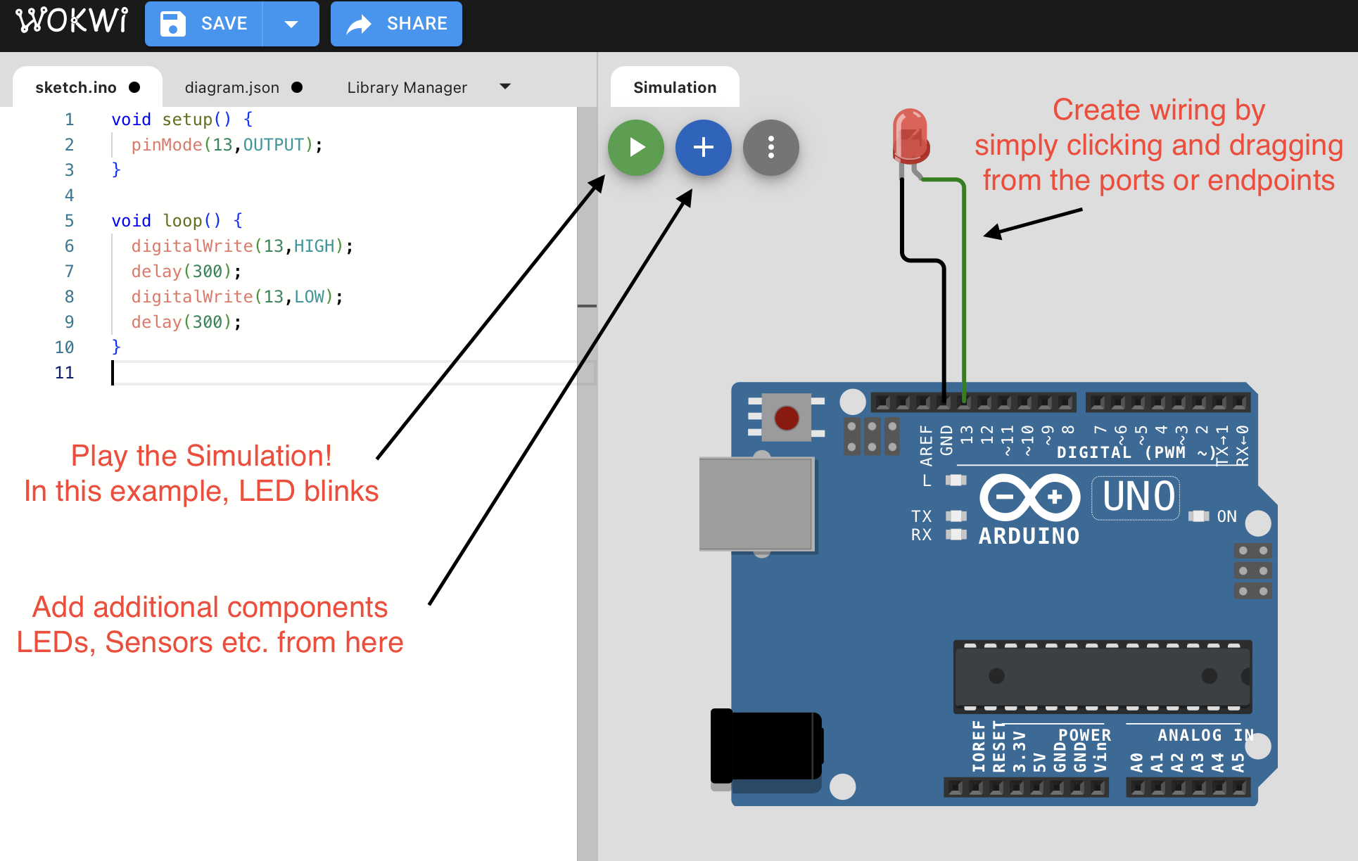
Wokwi is a free and easy to use online simulator for microcontrollers. After the microcontroller is chosen, we can see here the interface with the programming canvas on left and simulated hardware set-up to the right.
There are buttons to start the simulation as well as to add components. Wiring is easily accomplished by simply clicking a pin on the microcontroller or on the component and just dragging it to the endpoint.
Here is a simple program, goal being to understand "INPUT_PULLUP" and its importance. Basically pullup is a directive to internally connect the pin to power through a resistor. The appropriate value of resistor can be found using Ohm's law, keeping in mind that the voltage drop across different color LEDs will vary.
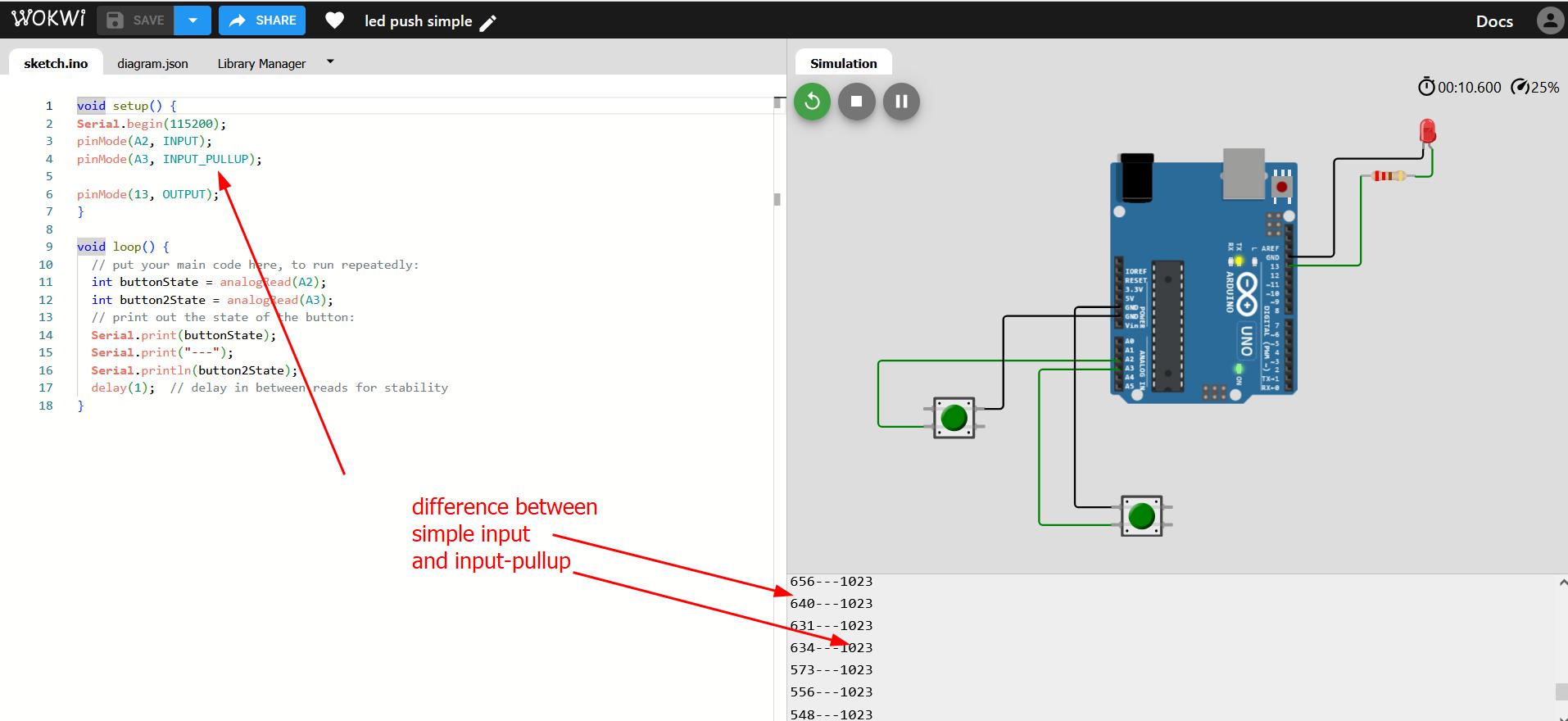
Choosing resistor value: to choose the resistor value, we use Ohm's law. The red LED such as we use has a smaller forward voltage, around 2 V. This means that a smaller voltage is required to turn it on, and for this reason we'll need a larger resistor value to "eat up" that voltage. Using V=IR with V at a value of 3 and I = 20 mA, we calculate a required resistance value of 150 Ohm. We round up and use a 220 Ohm resistor in these examples.
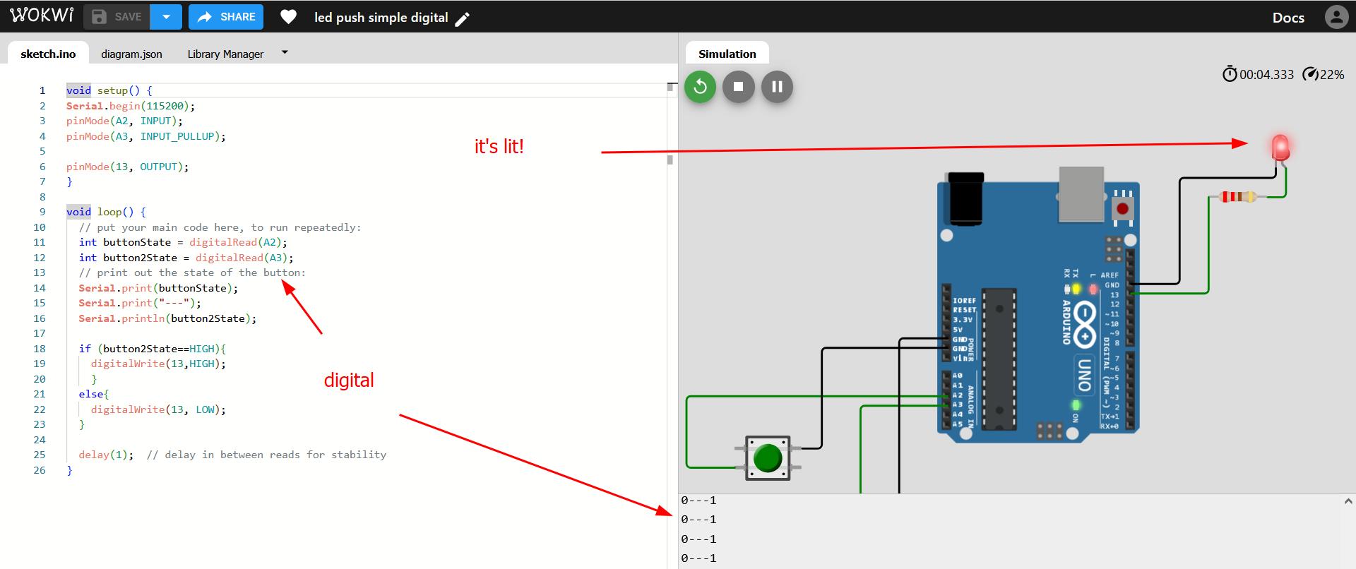
In this follow-up program, the LED is toggled by the 2nd button, but it's not possible by the first button because it is not "pulled-up" and hence unstable.
void setup() {
//start the serial communication at specific BAUD rate
Serial.begin(115200);
//specify the pins and their function
pinMode(A2, INPUT);
pinMode(A3, INPUT_PULLUP);
pinMode(13, OUTPUT);
}
void loop() {
// determines the value of the variable by reading from pins
int buttonState = digitalRead(A2);
int button2State = digitalRead(A3);
// prints out the state of the button
Serial.print(buttonState);
Serial.print("---");
Serial.println(button2State);
// main conditional determining whether to turn the LED on or off
if (button2State==HIGH){
digitalWrite(13,HIGH);
}
else{
digitalWrite(13, LOW);
}
// delay in between reads for stability
delay(1);
}
Eventually as a group in Kochi we abandoned the Arduino simulator as it too often failed to run.
Raspberry Pi PICO Simulations in WOKWI
Example 1 - LED with Switch:
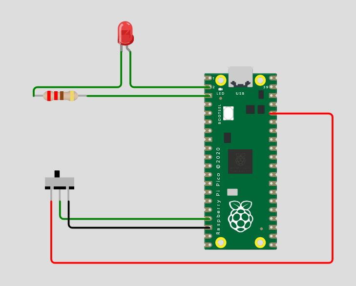
Here's the simple code. If you flip the switch the light goes out:
# import needed functions
import time
from machine import Pin
# Wait for USB to become ready
time.sleep(1)
# pin assignement
led=Pin(1,Pin.OUT)
switch = Pin(13, Pin.IN)
# main loop: reads input value and switches LED accordingly
while True:
if switch.value()==1:
led.high()
print('On')
if switch.value()==0:
led.low()
print('Off')
time.sleep(0.2)
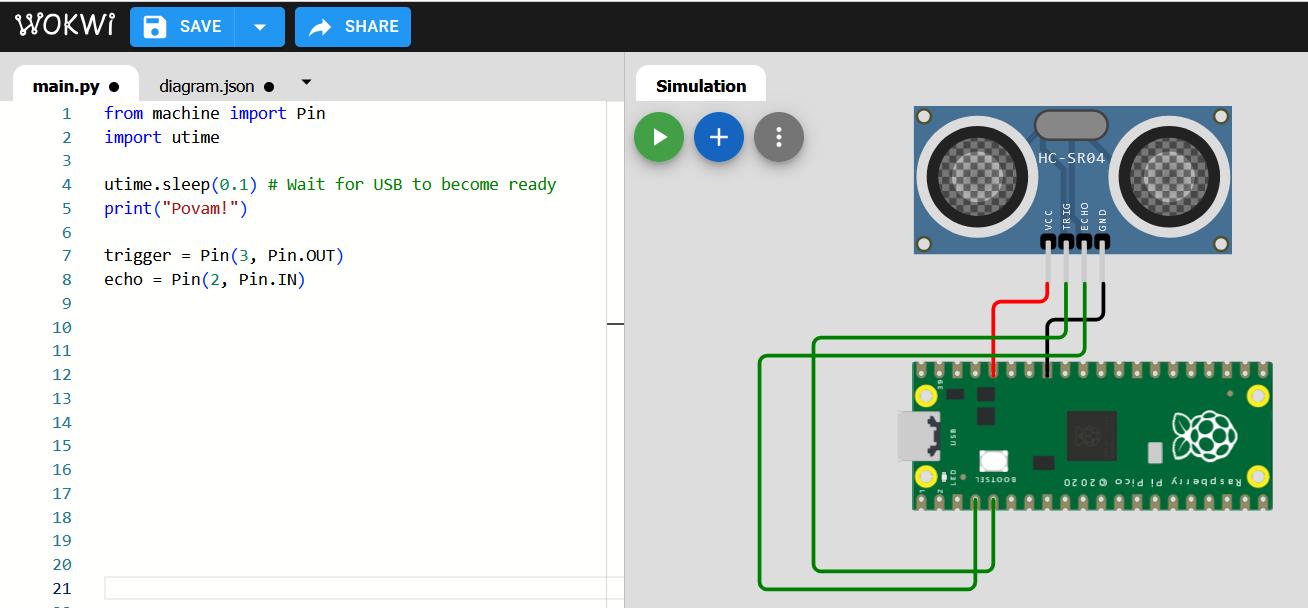
Example 2 - Ultrasonic:
We start by importing libraries, define pins, and wire the ultrasonic to the board. Just press 'R' to rotate the board.
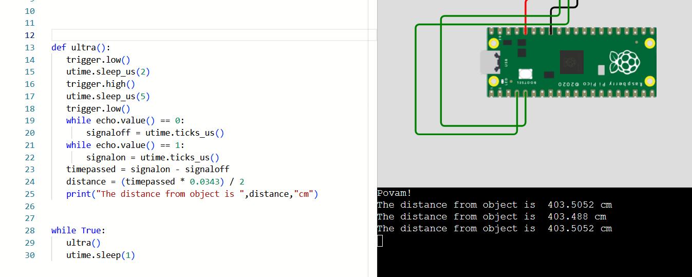
Now we import and test a function for the ultrasonic we found from Tom's Hardware. It works!
Example 3 - OLED:
We continue with the Ultrasonic and connect an OLED, including a library "ssd1306.py" which we copied from another OLED program on Wokwi. From there we additionally must include a function for the communication protocol which is difficult to understand.
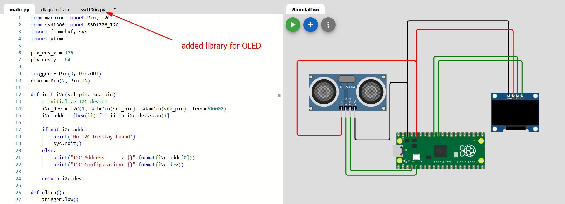
We add lines to the Ultra function to print to the OLED. We also define SDA/SCL pins. And it works alhamdulillah!
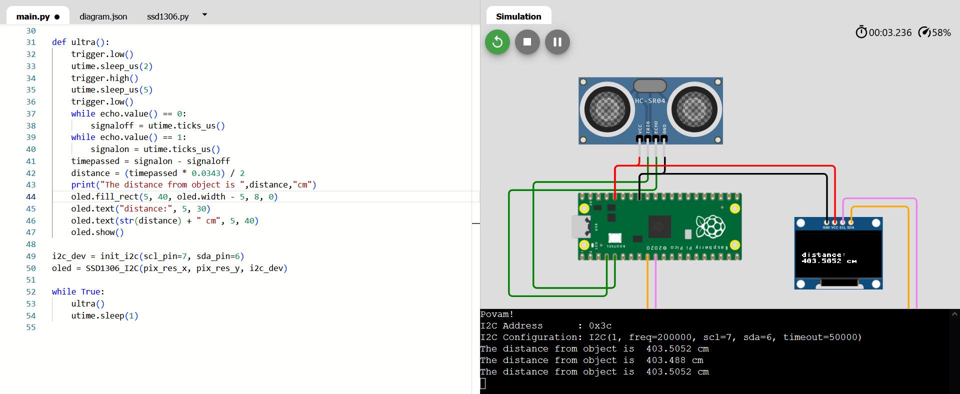
Here's the full code for this project:
# import functions
from machine import Pin, I2C
from ssd1306 import SSD1306_I2C
import framebuf, sys
import utime
pix_res_x = 128
pix_res_y = 64
# pin assignment
trigger = Pin(3, Pin.OUT)
echo = Pin(2, Pin.IN)
# function for initializing communication with OLED
def init_i2c(scl_pin, sda_pin):
i2c_dev = I2C(1, scl=Pin(scl_pin), sda=Pin(sda_pin), freq=200000)
i2c_addr = [hex(ii) for ii in i2c_dev.scan()]
if not i2c_addr:
print('No I2C Display Found')
sys.exit()
else:
print("I2C Address : {}".format(i2c_addr[0]))
print("I2C Configuration: {}".format(i2c_dev))
return i2c_dev
# function for determining the distance and printing it to OLED
def ultra():
trigger.low()
utime.sleep_us(2)
trigger.high()
utime.sleep_us(5)
trigger.low()
while echo.value() == 0:
signaloff = utime.ticks_us()
while echo.value() == 1:
signalon = utime.ticks_us()
timepassed = signalon - signaloff
distance = (timepassed * 0.0343) / 2
print("The distance from object is ",distance,"cm")
# Clear the specific line by drawing a filled black rectangle
oled.fill_rect(5, 40, oled.width - 5, 8, 0)
oled.text("distance:", 5, 30)
oled.text(str(distance) + " cm", 5, 40)
oled.show()
# setting up the communication and OLED
i2c_dev = init_i2c(scl_pin=27, sda_pin=26)
oled = SSD1306_I2C(pix_res_x, pix_res_y, i2c_dev)
# main loop
while True:
ultra()
utime.sleep(1)
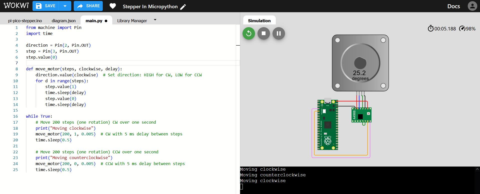
Example 4 - Stepper Motor:
We wire up the Stepper Motor, however our example code is only in Arduino, so we must research how it can work in Micropython.
With some difficulty, research and help from perplexity.ai, we got the code working just for the single step motor to work.
Example 5 - All Together:
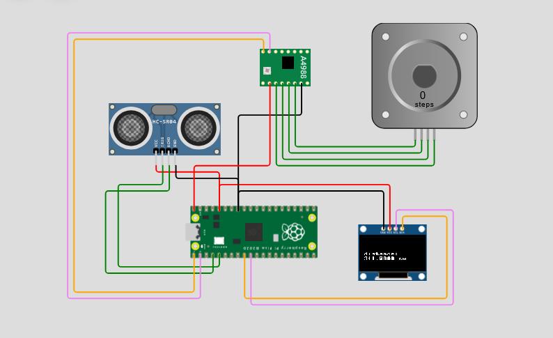
Final step is to bring this separate code for the stepper motor into our main program with the ultrasonic and OLED screen:
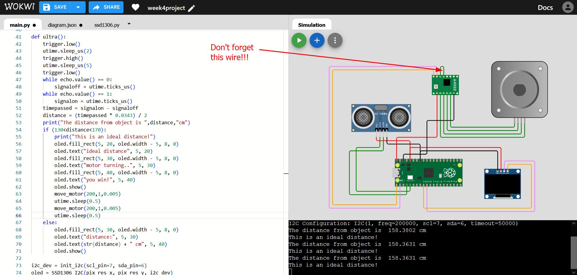
Everything seemed to be fine, but the stepper motor didn't move! Turns out we forgot the reset-sleep connection on the driver.
After we fixed that connection on the motor driver, everything worked fine. Here's a diagram of the driver sourced from here.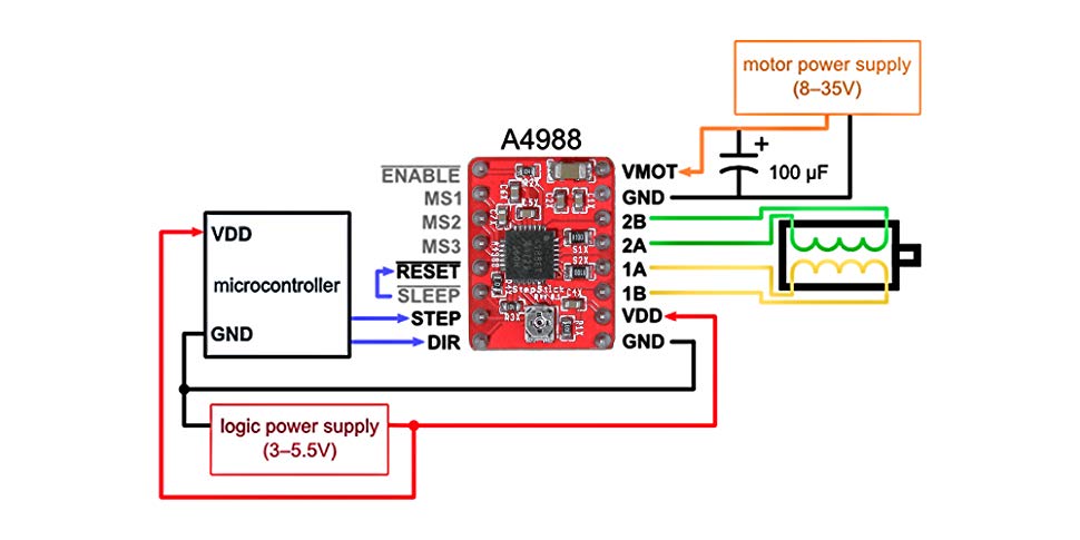
When I prepared to make a video, there were a couple imperfections, namely that the motor didn't reverse and part of the OLED display did not clear, but I was able to fix these coding issues and then make a screen recording:
Full code for the end of week project follows, and the project can also be found on Wokwi here.
# import functions from respective libraries
from machine import Pin, I2C
from ssd1306 import SSD1306_I2C
import framebuf, sys
import utime
# Wait for USB to become ready
utime.sleep(0.1)
# print something for testing
print("Povam!")
# pin assignment
direction = Pin(0, Pin.OUT)
step = Pin(1, Pin.OUT)
step.value(0)
trigger = Pin(3, Pin.OUT)
echo = Pin(2, Pin.IN)
pix_res_x = 128
pix_res_y = 64
# function for initializing communication with OLED
def init_i2c(scl_pin, sda_pin):
# Initialize I2C device
i2c_dev = I2C(1, scl=Pin(scl_pin), sda=Pin(sda_pin), freq=200000)
i2c_addr = [hex(ii) for ii in i2c_dev.scan()]
if not i2c_addr:
print('No I2C Display Found')
sys.exit()
else:
print("I2C Address : {}".format(i2c_addr[0]))
print("I2C Configuration: {}".format(i2c_dev))
return i2c_dev
# Function for step motor movement, 1.8 degrees per step; allows us to specify precisely how to move the motor
def move_motor(steps, clockwise, delay):
direction.value(clockwise) # Set direction: HIGH for CW, LOW for CCW
for d in range(steps):
step.value(1)
utime.sleep(delay)
step.value(0)
utime.sleep(delay)
# Main function of the program, the outputs (motor and display) depends on the distance reported by ultrasonic sensor
def ultra():
trigger.low()
utime.sleep_us(2)
trigger.high()
utime.sleep_us(5)
trigger.low()
while echo.value() == 0:
signaloff = utime.ticks_us()
while echo.value() == 1:
signalon = utime.ticks_us()
timepassed = signalon - signaloff
distance = (timepassed * 0.0343) / 2
print("The distance from object is ",distance,"cm")
if (130<distance<170):
print("This is an ideal distance!")
oled.fill_rect(5, 20, oled.width - 5, 8, 0)
oled.text("ideal distance", 5, 20)
oled.fill_rect(5, 30, oled.width - 5, 8, 0)
oled.text("motor turning..", 5, 30)
oled.fill_rect(5, 40, oled.width - 5, 8, 0)
oled.text("you win!", 5, 40)
oled.show()
move_motor(200,1,0.005)
utime.sleep(0.5)
move_motor(200,0,0.005)
utime.sleep(0.5)
else:
oled.fill_rect(5, 20, oled.width - 5, 8, 0)
oled.text("not right", 5, 20)
oled.fill_rect(5, 30, oled.width - 5, 8, 0)
oled.text("distance:", 5, 30)
oled.text(str(distance) + " cm", 5, 40)
oled.fill_rect(5, 40, oled.width - 5, 8, 0)
oled.text("you lose!", 5, 40)
oled.show()
# setting up the communication and OLED
i2c_dev = init_i2c(scl_pin=7, sda_pin=6)
oled = SSD1306_I2C(pix_res_x, pix_res_y, i2c_dev)
# main loop
while True:
ultra()
utime.sleep(0.5)
Group Assignment Reflection
This was a meaningful week, and I learned a lot, as I had previously only experience with making some projects with Arduino Uno and Raspberry Pi (where I did also use Thonny). In any case, having this small XIAO RP2040 microcontroller in the palm of my hand, and then proceeding to the documentation (datasheet) was a revelation in terms of understanding the architecture behind / inside it. It was likewise informative how the same microcontroller could be programmed in different ways, from different programming environments.
As a group we investigated various other microcontrollers such as Attiny 1614, and I learned a lot about the full power of the Arduino IDE to program a wide variety of boards and the workflow to set that up. Likewise we were introduced to "programmer" board, which was a completely new idea. In summary, we learned about the architecture of the boards available through their respective datasheets, and about the associated toolchains, i.e. the process of sending the program from our computer and coding environment to the board. A nice week.