Week 3: Computer-Controlled Cutting
Group Assignment (link): do your lab's safety training characterize your lasercutter's focus, power, speed, rate, kerf, joint clearance and types
Individual Assignment: 1) cut something on the vinylcutter 2) design, lasercut, and document a parametric construction kit, accounting for the lasercutter kerf, which can be assembled in multiple ways
Vinyl Cutter:
Part I: Design Selection and Preparation
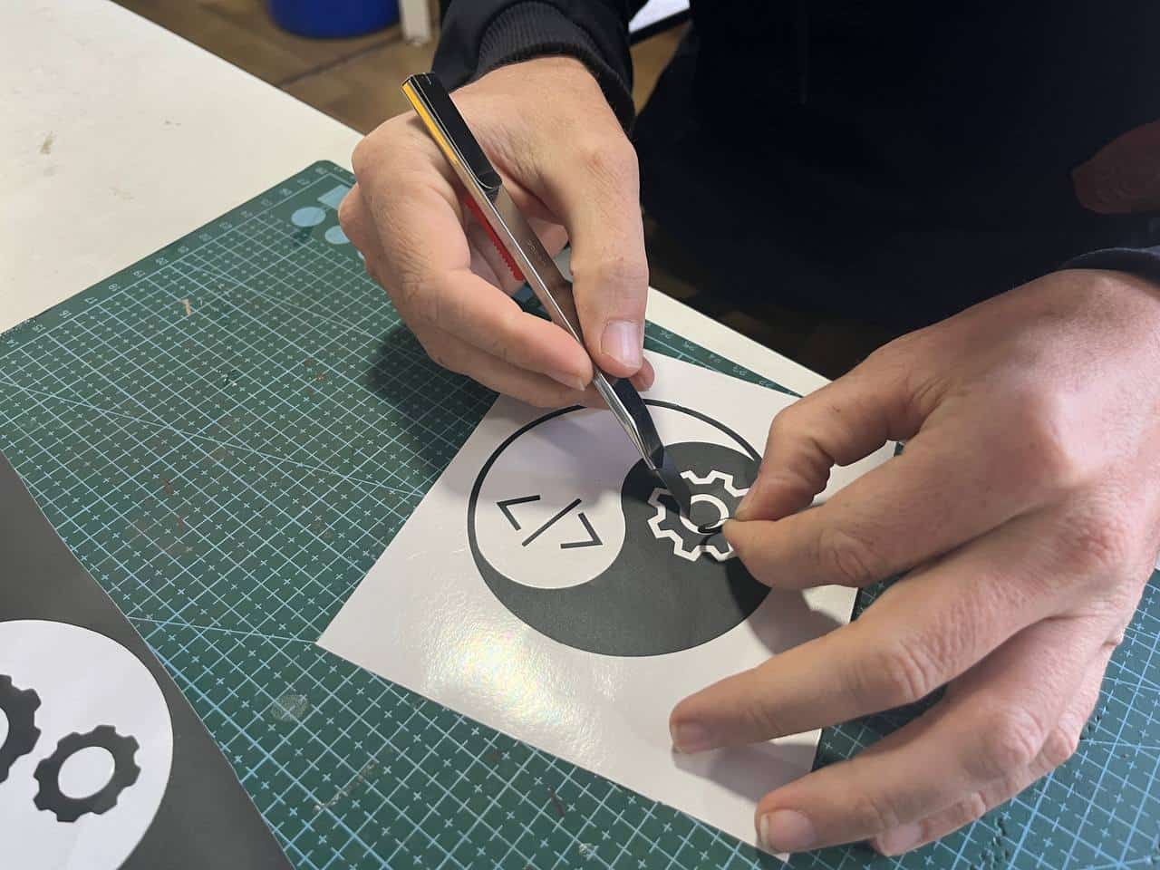
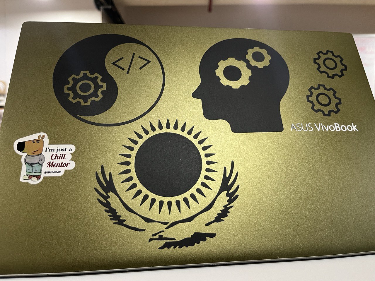
I've got a business and it has a logo, designed by "Chico Mysterioso". Of course I want this on my laptop. Let's go!!!
Initially there were some issues with processing. Specifically for Vinyl cutting we must remove the stroke and make it black
Later we also took the image of the kazakhstan flag for vinyl cutting, following the same process.

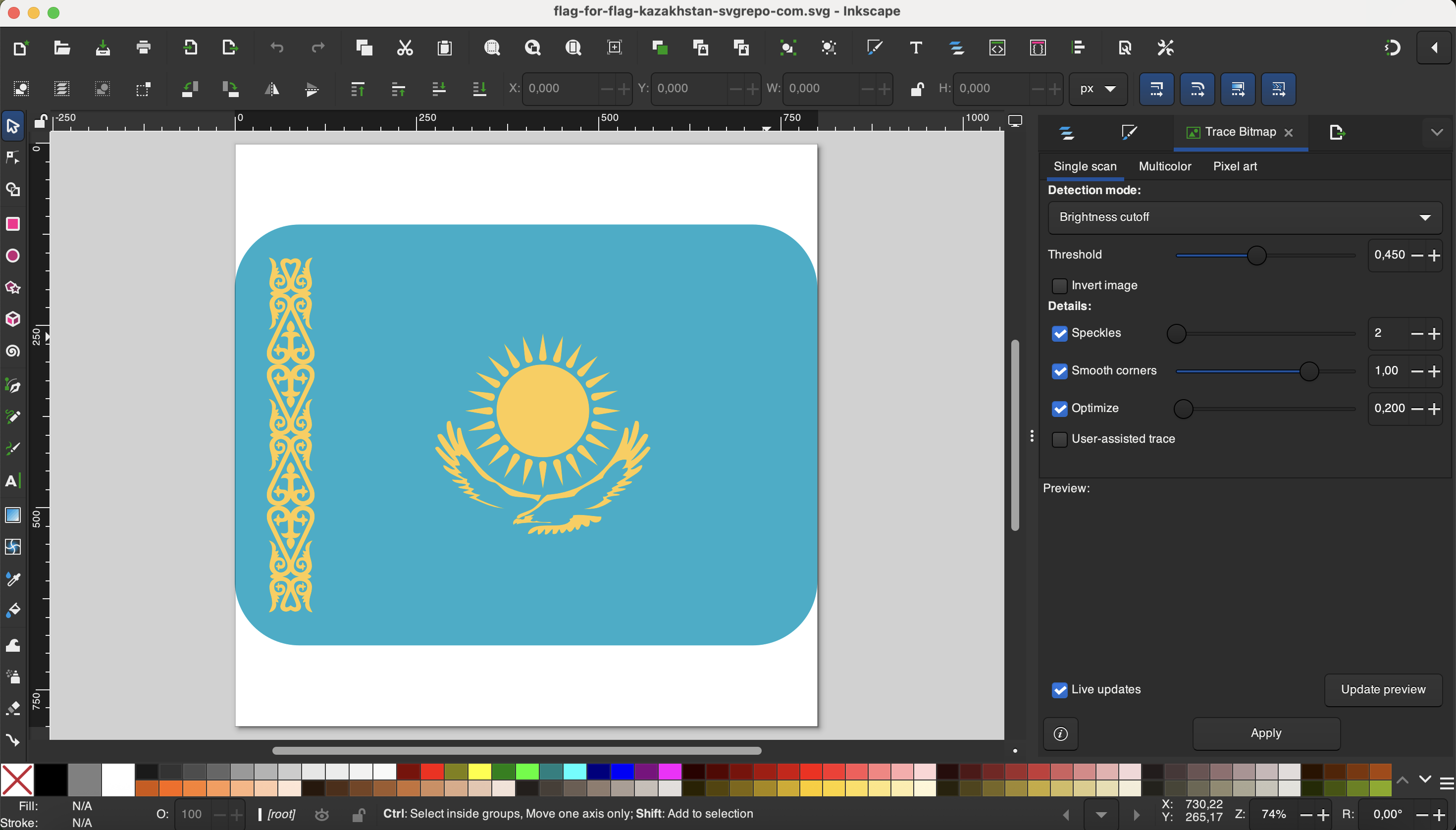
We got the .svg file from an SVG repository here. The design is a great use-case for the vinyl cutter due to the intricate details.
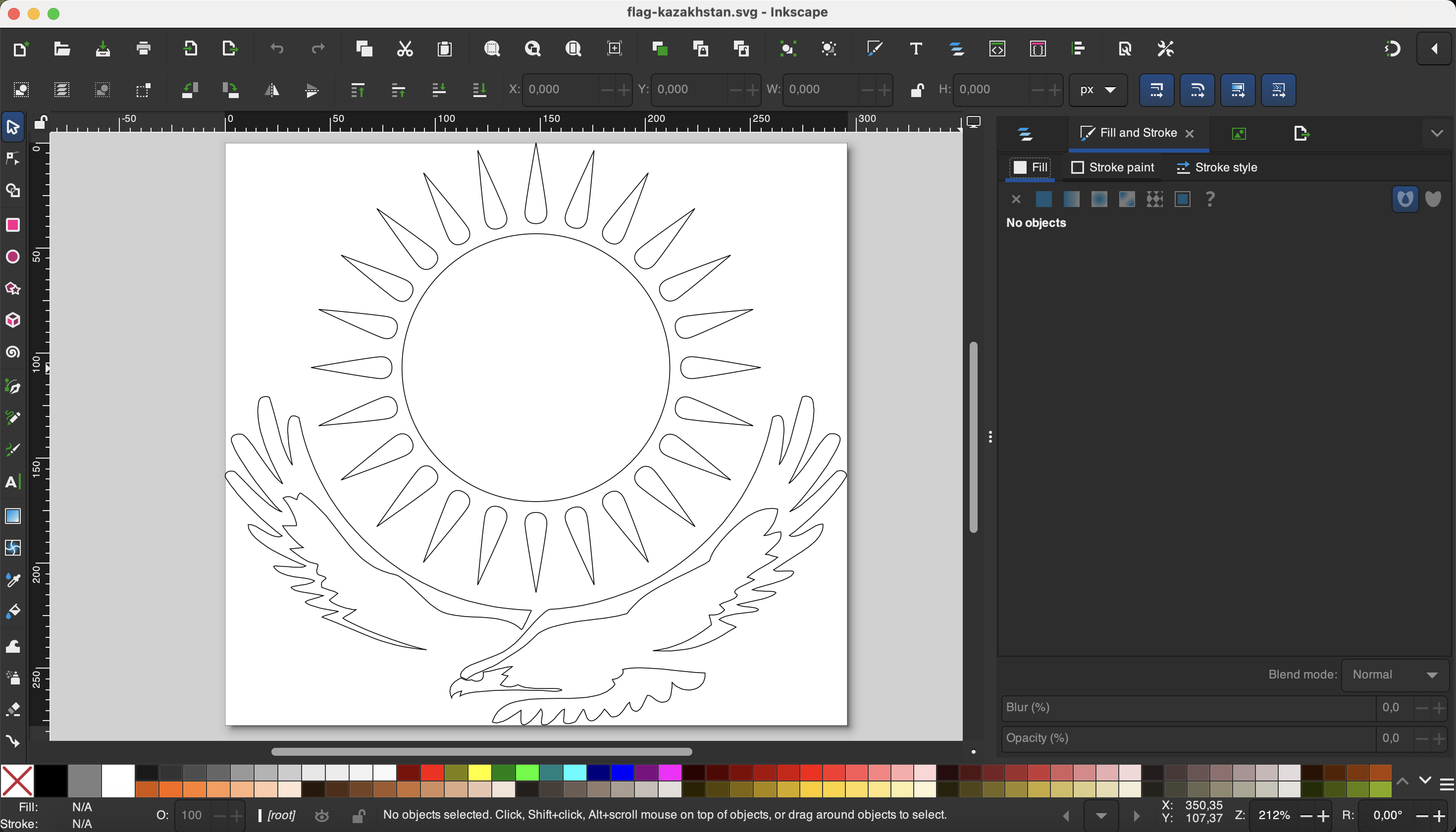
However we did need to spend some time preparing the image in inkscape, by removing the fill and tracing a path. We started with this:
Then transformed it to a simple outline for the vinyl cutting:
Part II: Operating the Vinyl Cutter
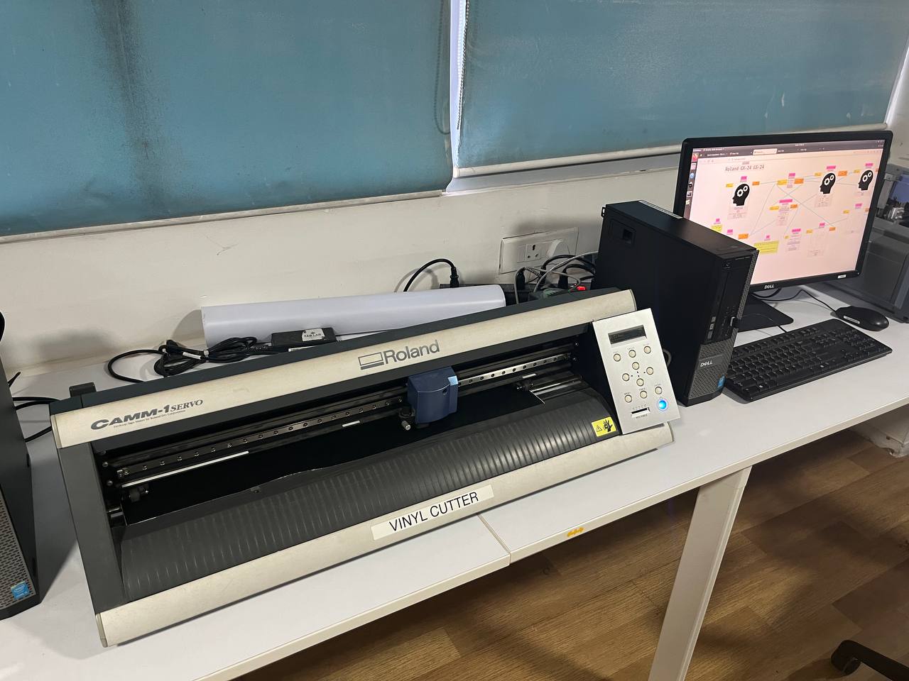
Here's the machine we will use. It's a GS-24 Roland Vinyl Cutter. On the right we have the computer we use to process and send the file to the cutter.
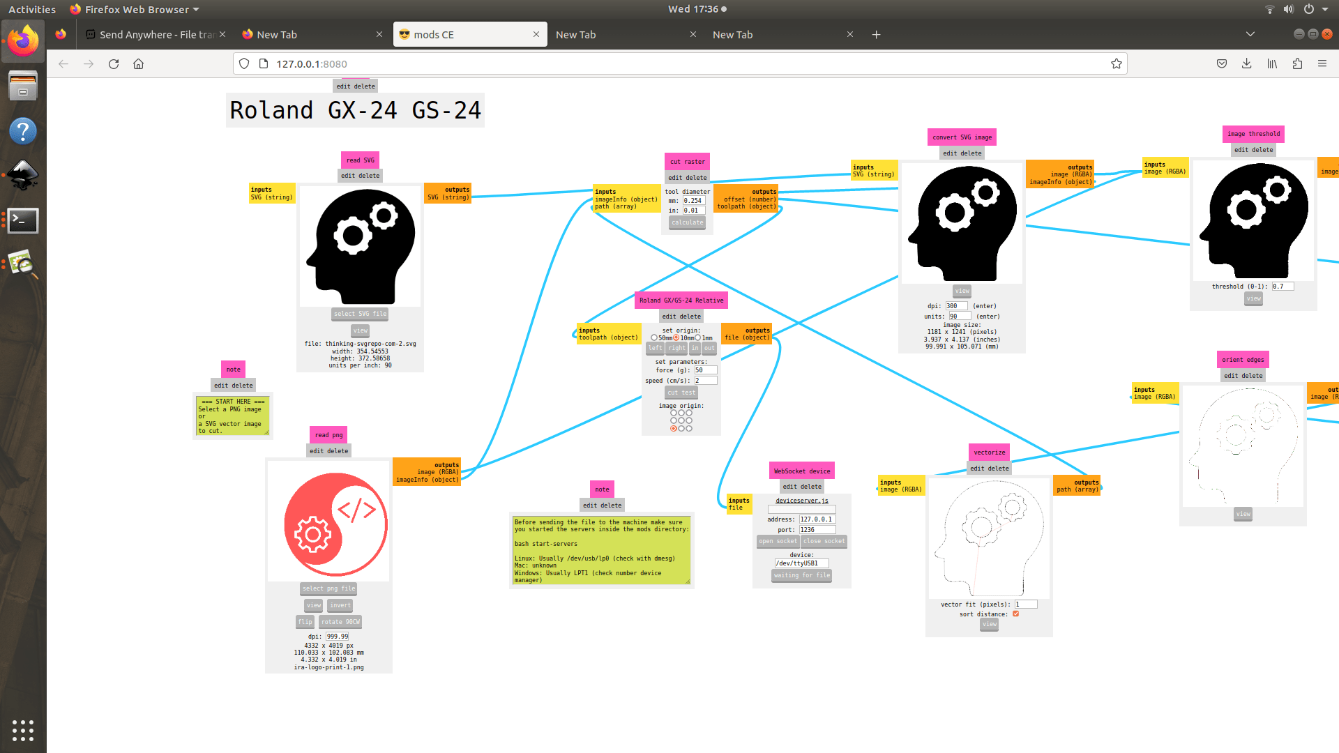
This is the software interface. The interface is called "Mods" and was developed by Dr. Neil. Check it out here: modsproject.org. This software may be used to prepare toolpaths for a variety of machines.
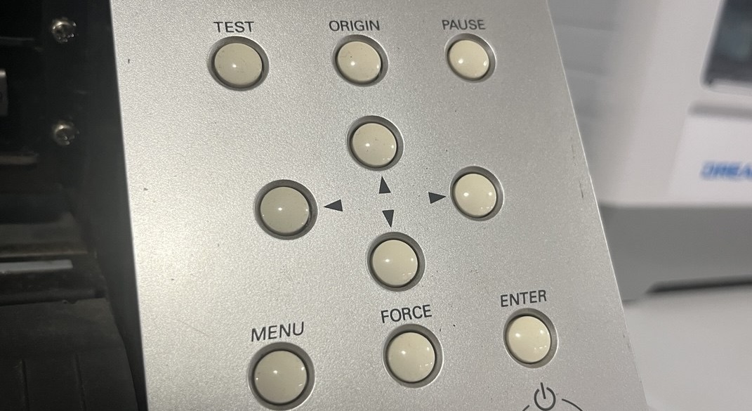
Before cutting, we must also do some set-up on the Vinyl cutter itself, using its button interface shown below. We will use this interface not only to position the start of the job, but also to set parameters for both speed and force.
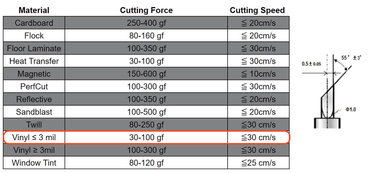
Depending on the material type, different levels of speed and force will be required to cut. The following
table lists some suggested parameters for different materials. As we are cutting a thin vinyl, a relatively high
speed like 30 cm/s and a relatively low force like 50 gf (grams-force), should be sufficient.
Image credit.
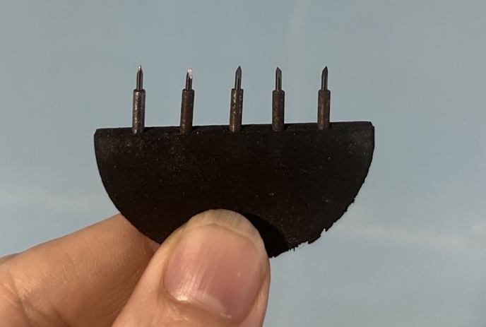
It's also possible to switch the type of blade depending on the material to be cut; however we were all using the same type of material, so it was unnecessary, though we saw the blades.
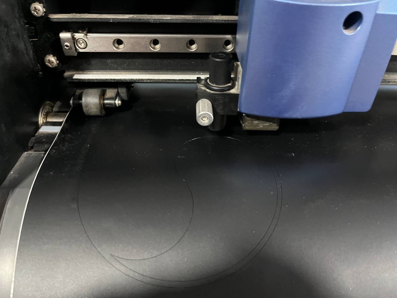
Finally we can start the project and watch it cut!! Very nice, very smooth:
Part III: Sticker Application
1. Remove the non-essential parts of the design.
2. Take a piece of sticky tape and remove the back.
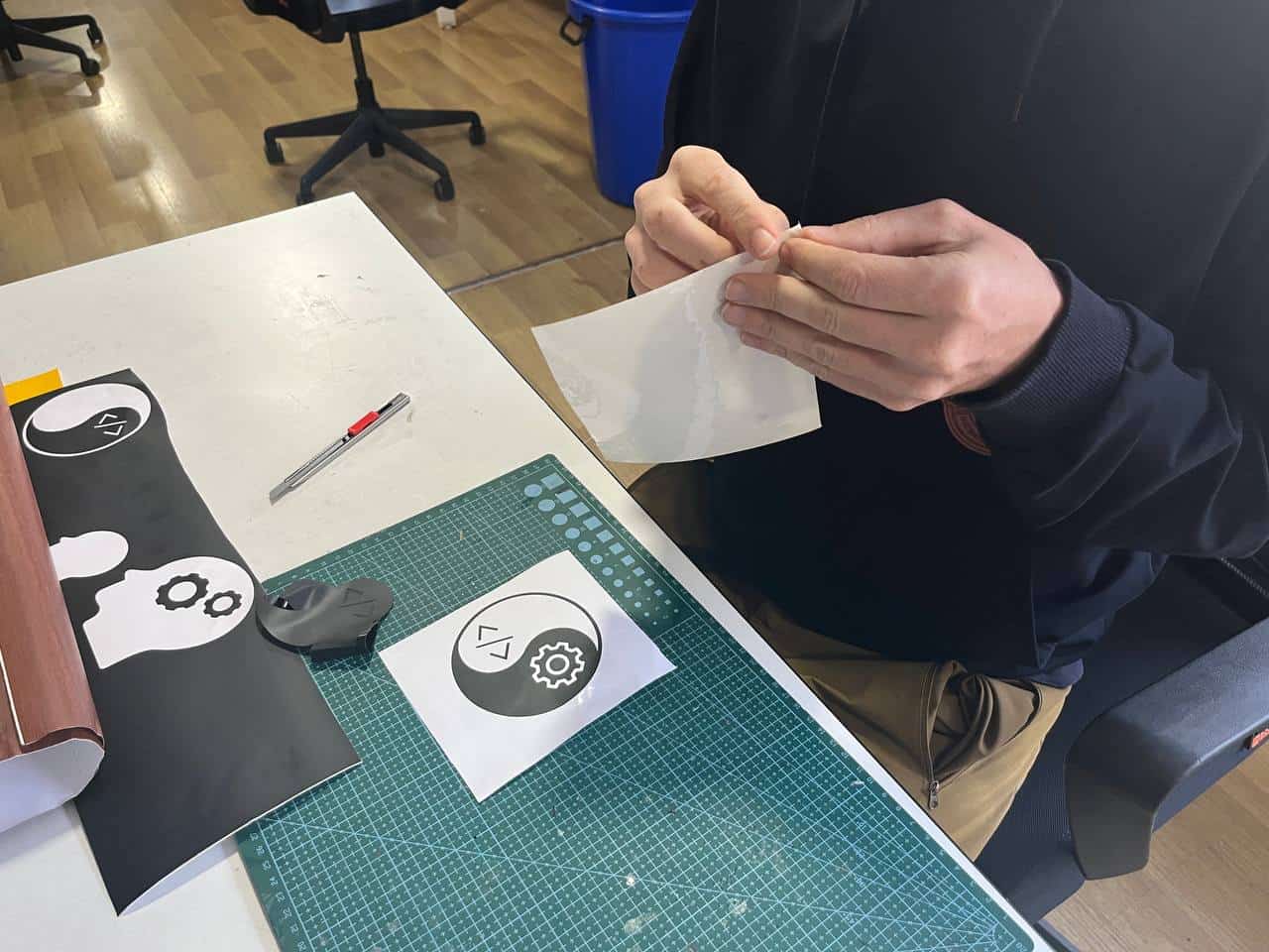
3. Press the sticky tape on the image.
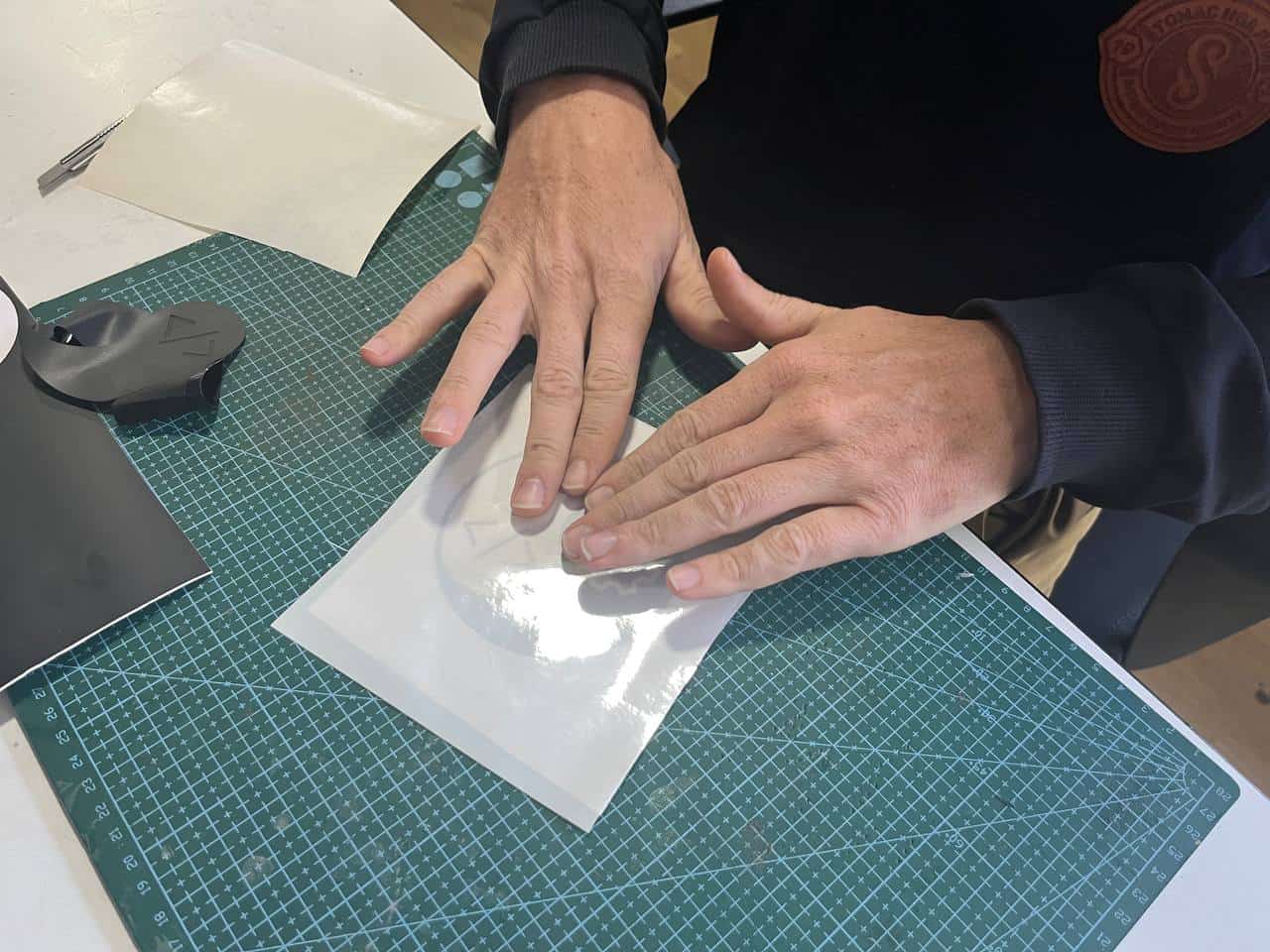
4. Now the design is ready for transfer.
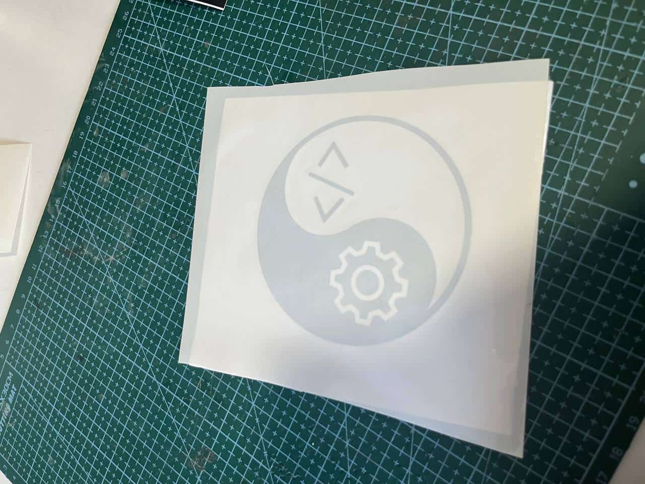
5. Installed the vinyl cutouts professionally. Laptop increases value.
Parametric Construction Kit
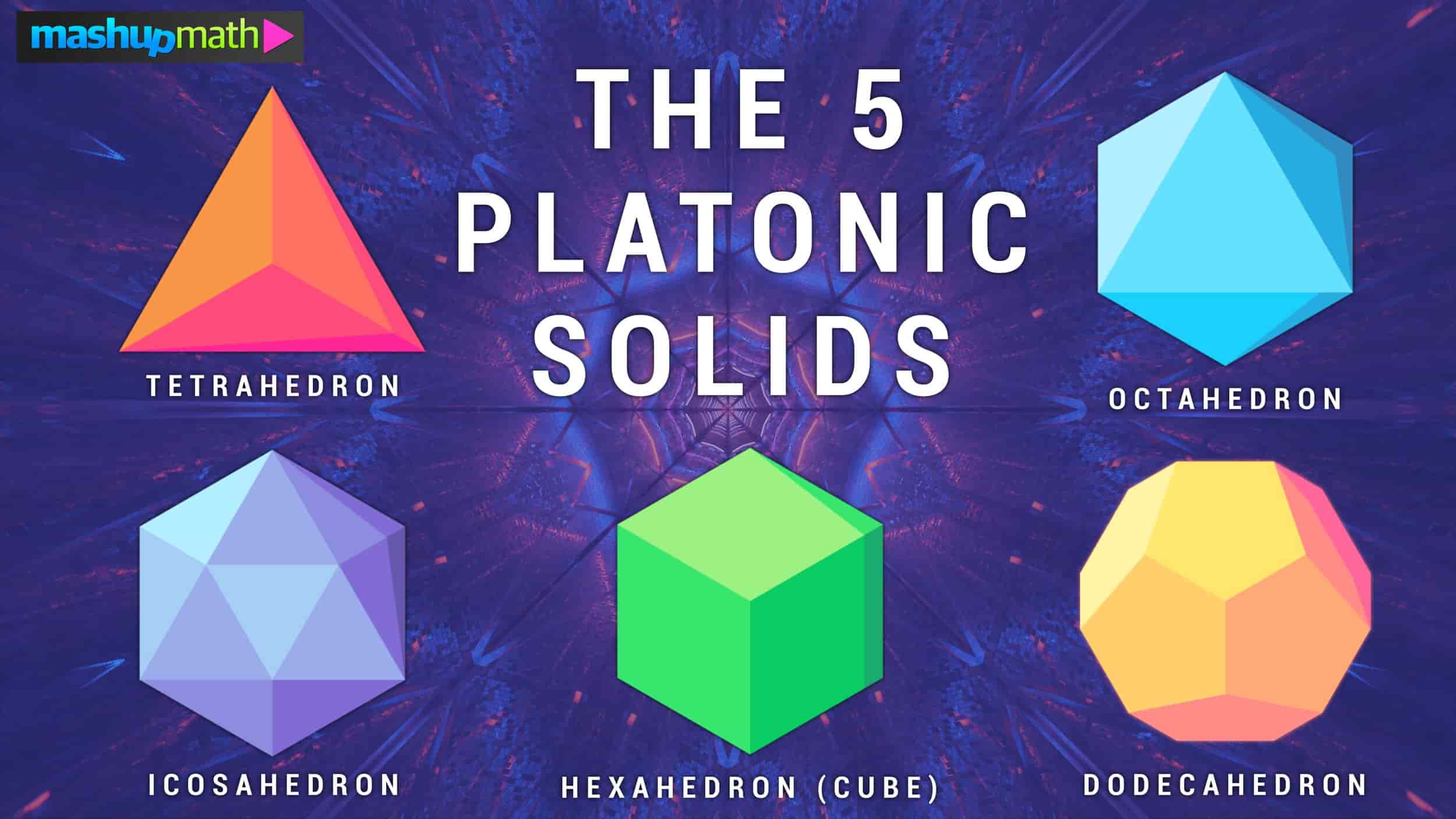
Triangular-based Platonic Solids:
In the Kochi lab is a parametric construction kit for a dodecahedron, the best of all the platonic solids.
However, 3 of the 5 platonic solids are made from equilateral triangles, so obviously a good option will be to make a construction kit for the triangular faced platonic solids.
Kerf is a new and important concept - it refers to the laser beam width. Generally speaking it is the width of material that is destroyed by the cutting instrument. When we are cutting something with the laser, it is burning material. So if we cut out a square from a shape, and try to fit it back in, it will not fit tightly. Of course! because the material around the square has been burned. Here is the square which I cut with instructor Saheen:
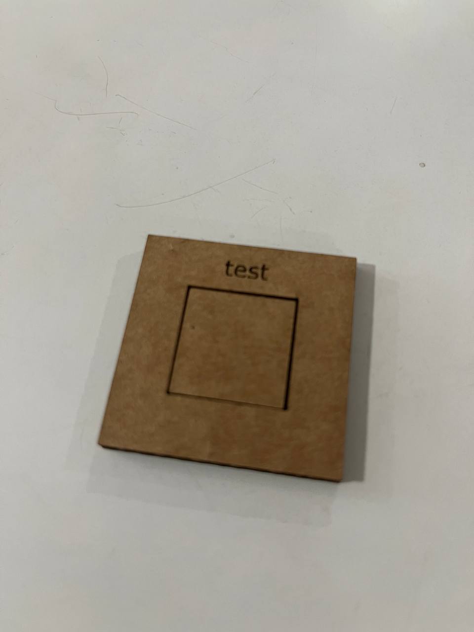
Using calipers, measure both the inside and the outside of the square.
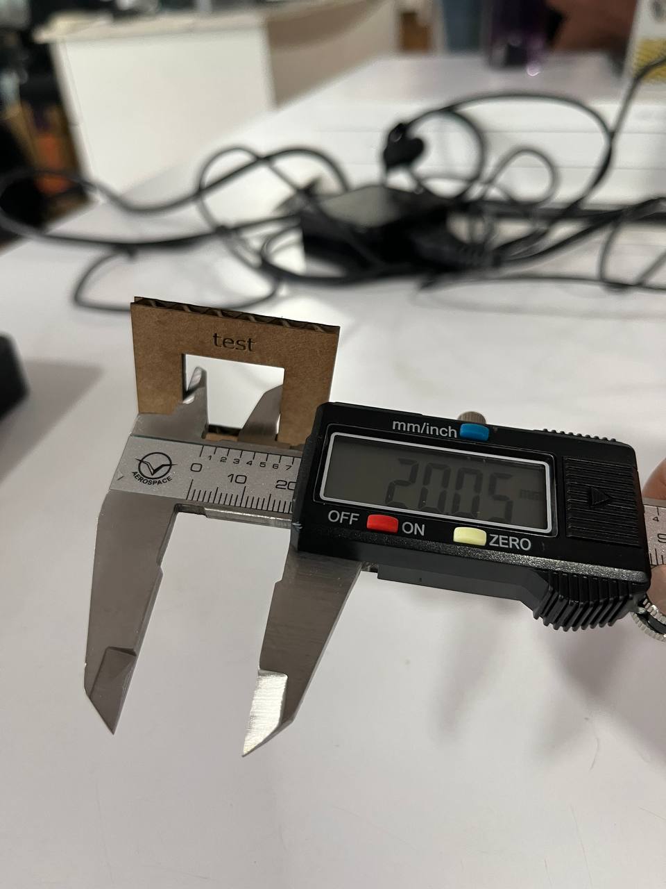
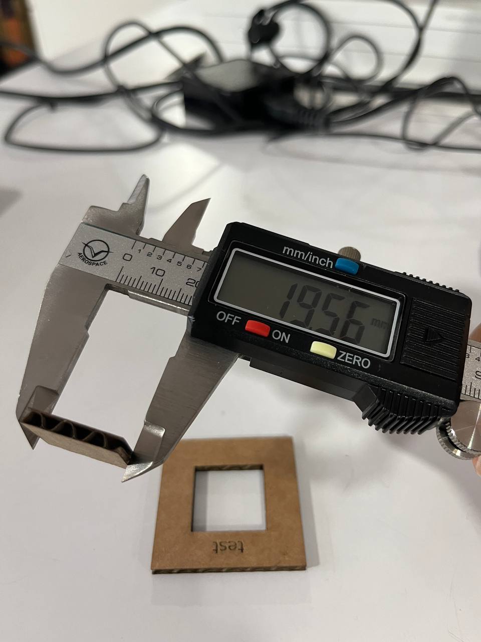
In our case the kerf is (20.05-19.56)/2=0.49/2=0.245. Here we divide by 2 to find the kerf since there are 2 cuts. Hence when we print we will offset by kerf/2=0.12mm. Then the square will fit securely.
Designing in Fusion 360:
After using FreeCAD and enjoying it, I was peer-pressured into using Fusion 360. Sad. So the first part of making the parametric kit was in Fusion 360. It involved:
- Sketching the entire triangle and connectors with constraints
- Extruding and adding the chamfer
- Added the parameters
- Projecting the sketch onto a face, and exporting the sketch as a .dxf file
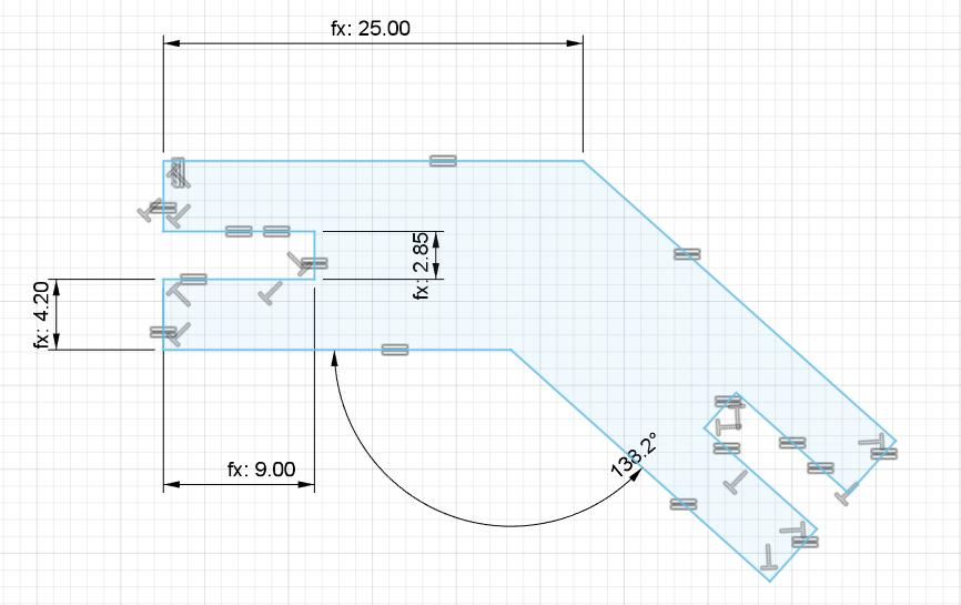
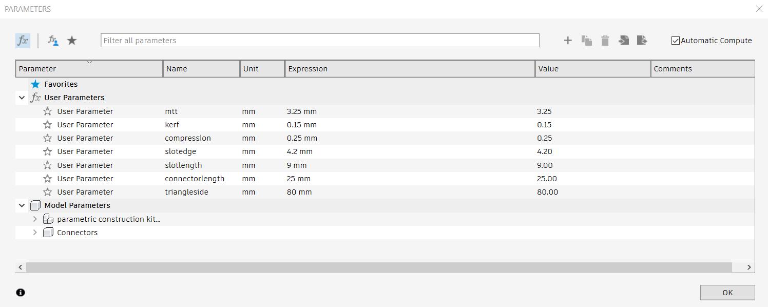
Creating a parametric design is very important. Here we have the designs for triangle and connectors:
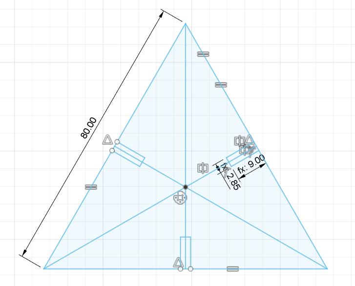
For context, the values for material thickness, kerf and compression were found by testing on the cardbaord using caliper.
The following parameters were used: (parameters can be found from the modify section of sketch menu.)
Cutting with Trotec:
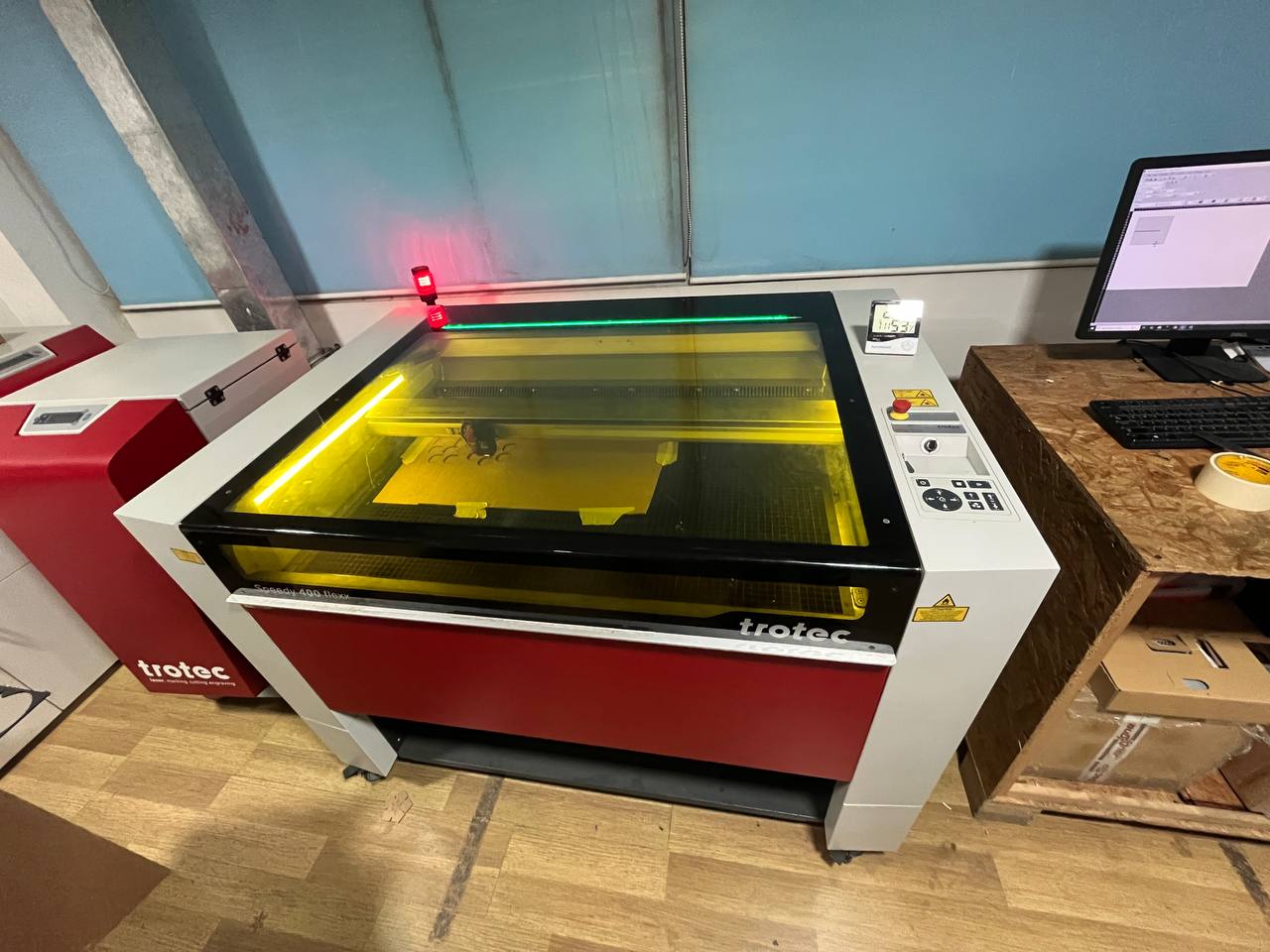
In the lab there is a nice laser-cutter: Trotec Speedy 400. On the left is the exhaust system and on the right is the computer which is connected and has the appropriate software for cutting.
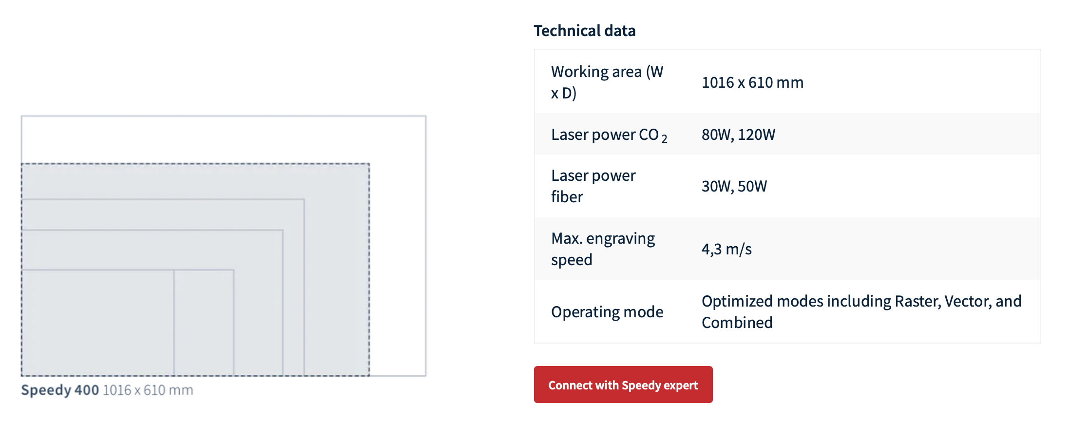
The vendor's website lists the parameters of this model:
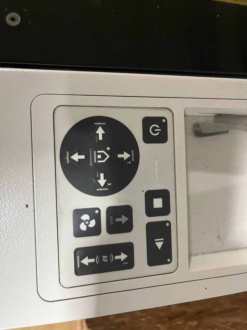
The power and controls are there. Important to calibrate each time by pressing the two buttons on the right. But the laser cannot be at the edge to calibrate, bring it towards the middle somewhere.
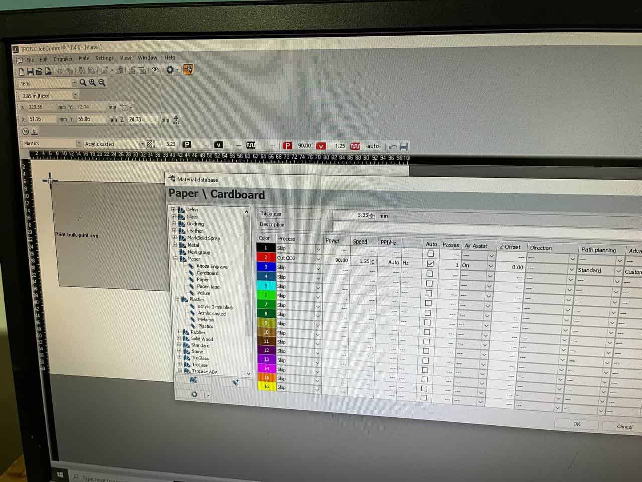
On the adjacent computer is software called "TROTEC Job Control", and is used to adjust settings like power and speed. These are recommended settings of power at 90 and speed at about 1.3 - for cardboard. Of course the power and speed will differ depending on the material used.
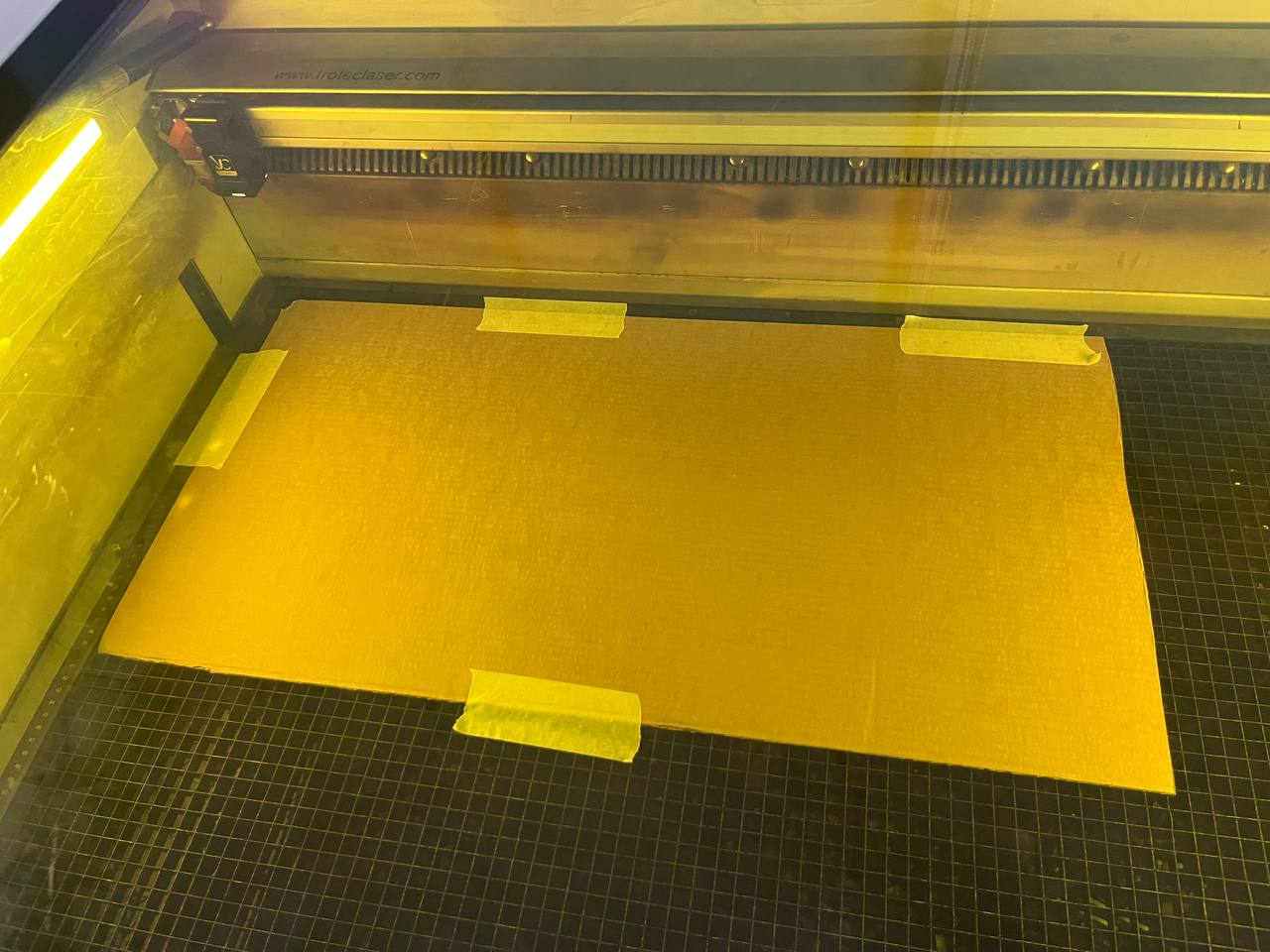
When we put the cardboard in, we must calibrate to the edges and hold it down with tape.
To prepare our file in inkscape we change the "stroke" to red color and give it a thickness of 0.01mm as can be seen in the screenshot below. These parameters (red stroke at 0.01mm) are recognized as cutting operstion.
After this, for cutting our project we simply go to "print" from within Inkscape. Then in TROTEC we place the file onto the "cutting board". It automatically shows the size. Then click "ready".
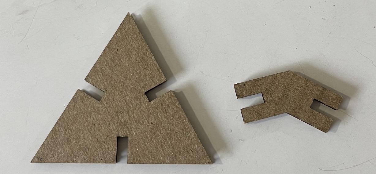
First we wanted to cut a few of the objects as a test:
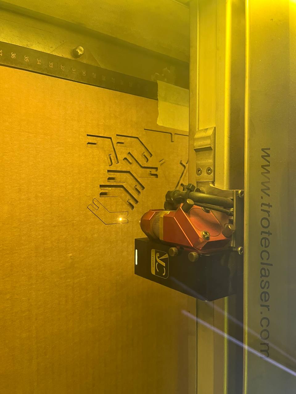
It was good, but needed to be adjusted for both the kerf and cardboard compression. However, it was very helpful to have parameters, and we could quickly change the appropriate values; the changes were automatically implemented both on the triangle and the connectors.
Workflow for production of the entire kit:
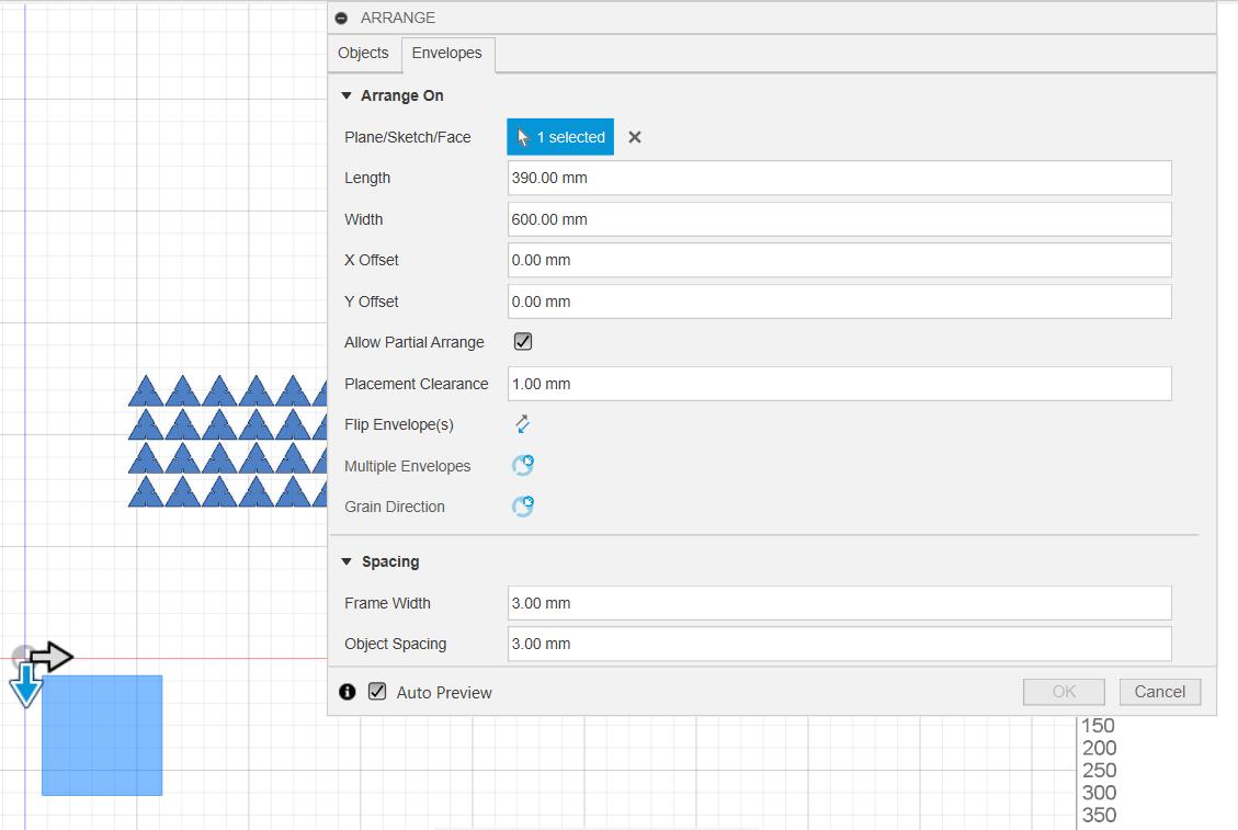
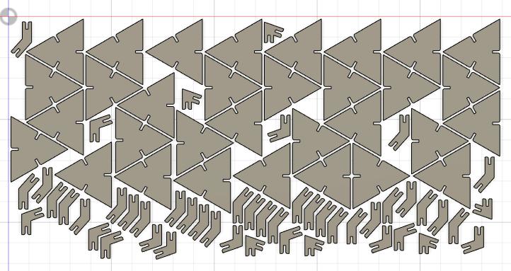
To produce the full kit, we need to make copies and arrange them. Fortunately there is an arrange function in Fusion 360. This is known as "nesting".
From Fusion we should then prepare the whole construction kit in Inkscape to send to the laser-cutter
Preparation in inkscape:
- export the file from Fusion in .dxf format.
- open the .dxf file in Inkscape, fitting the size (shortcut: Ctrl+Shift+R)
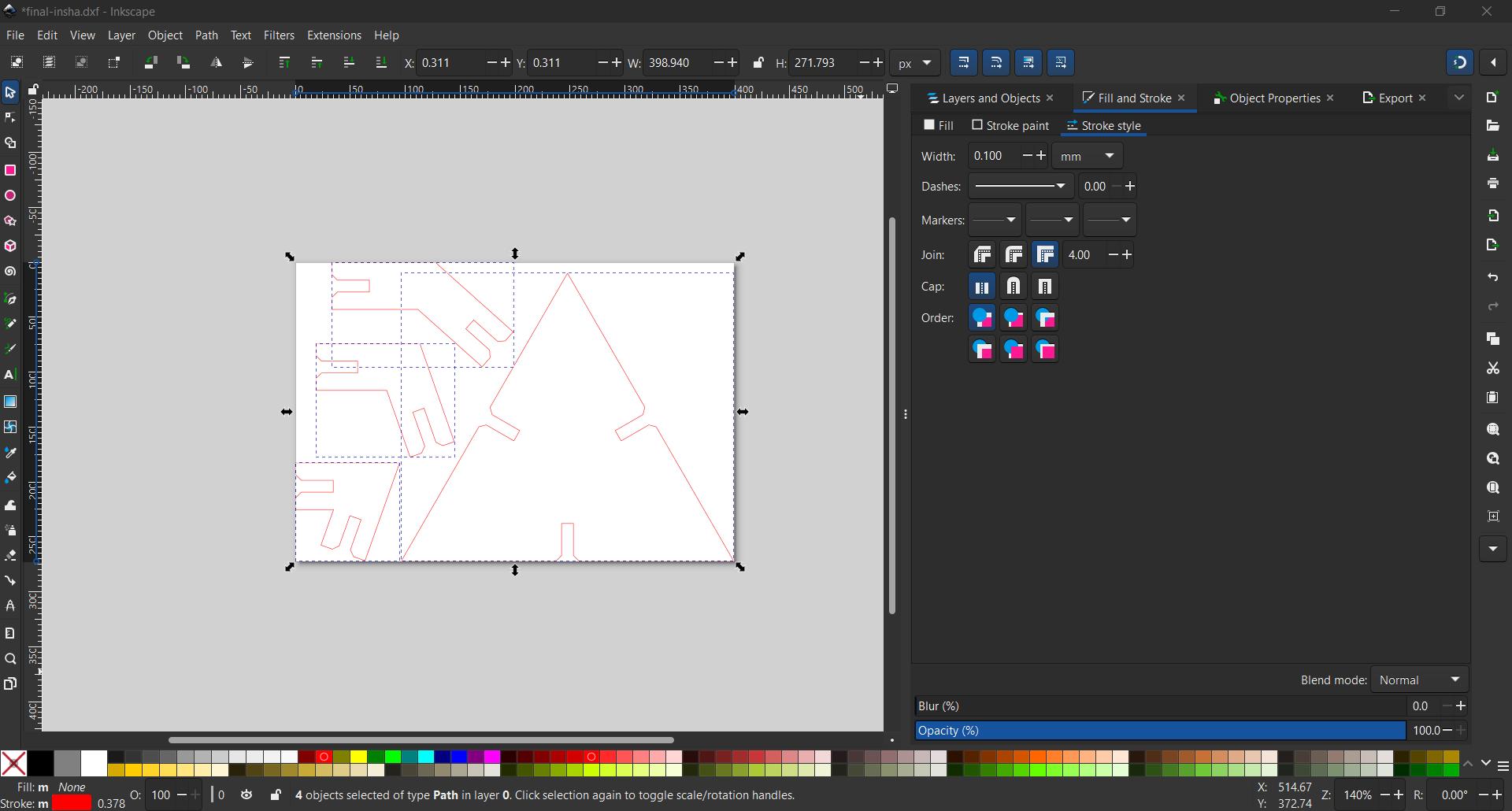
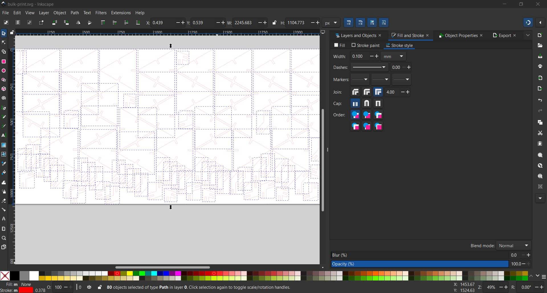
- in Inkscape, we set the stroke to red color of thickness 0.1 mm (and remove any fill).
- export the file from inkscape as .svg (shortcut: Ctrl+Shift+E)
- send the file from our computer to the laser cutter terminal using "send-anywhere" or similar
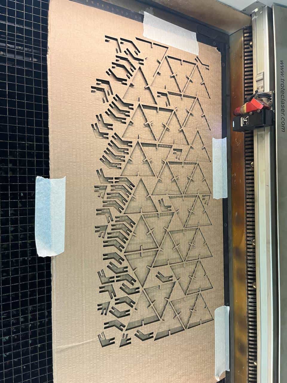
Cutting in Bulk:
Now it's time to print the entire parametric Kit! Here it is nearly done. Just took about 3 minutes:
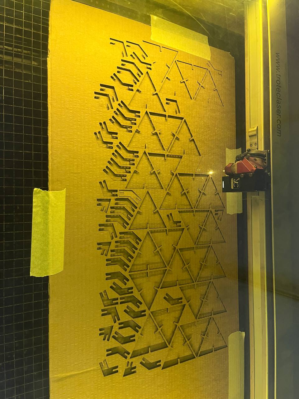
Note that the pieces have been cut cleanly and fallen out (appropriate speed and power settings)
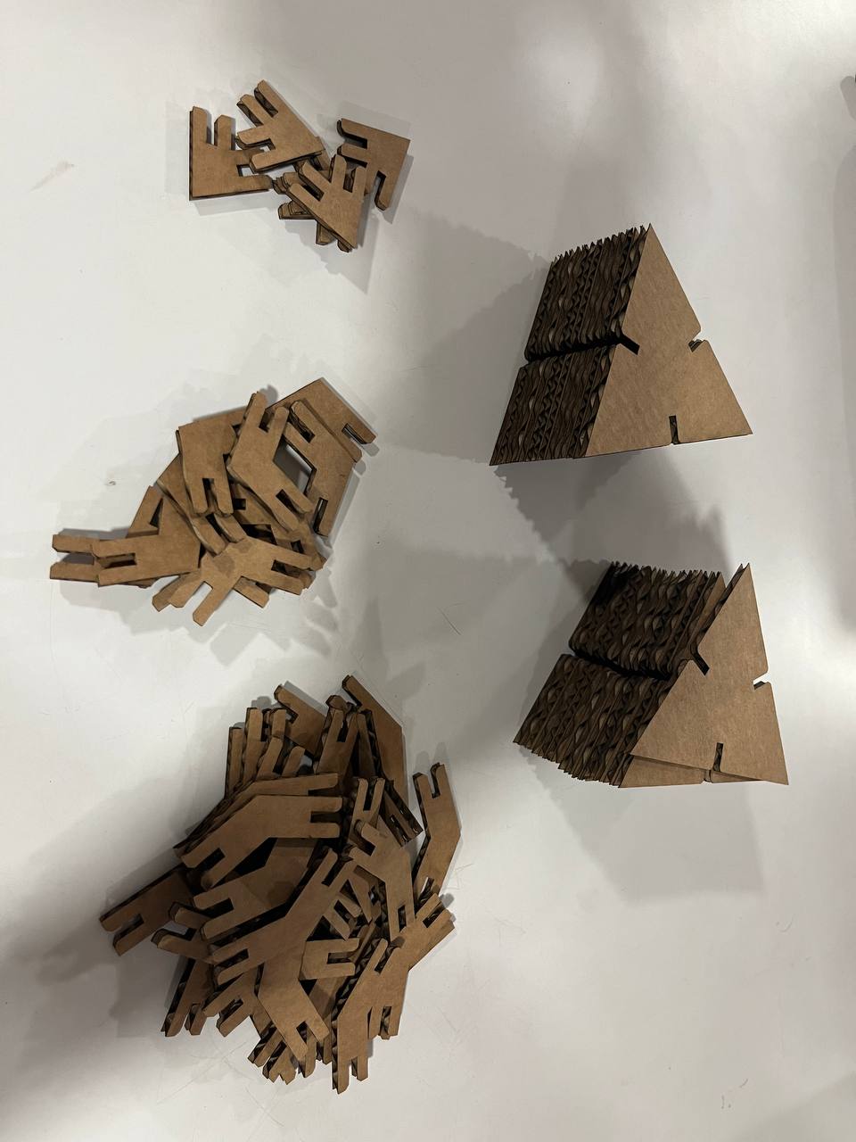
Here is the kit of construction pieces:
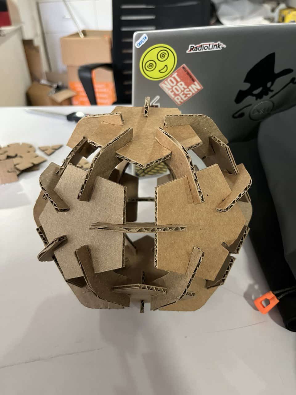
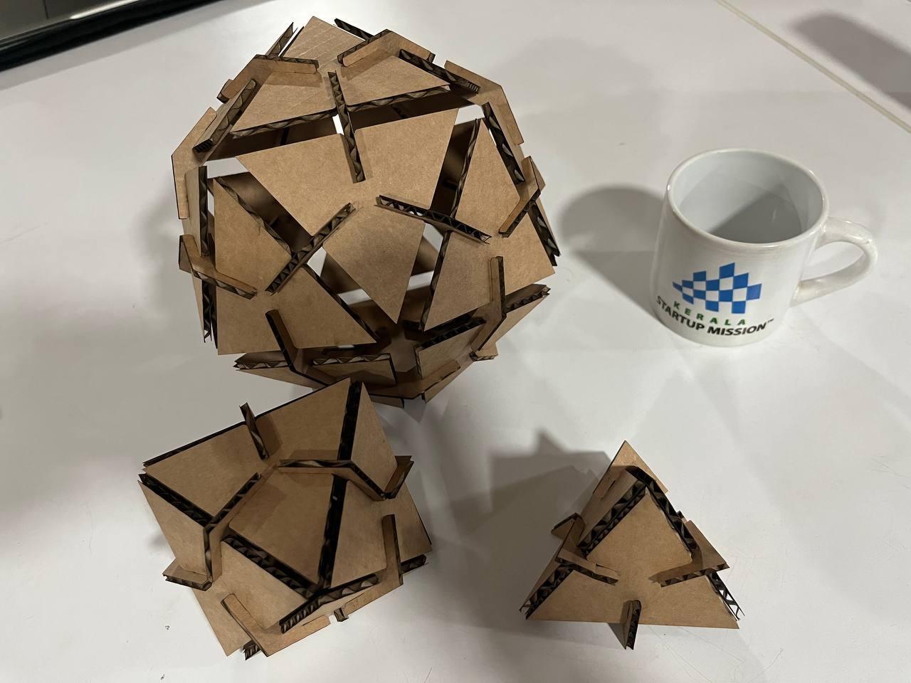
And here is the assembled triangular faced platonic solids - "Hero" shot.
Files:
- SVG File for Kazakhstan Flag - Vinyl cutter
- SVG File for laser cutting Parametric Construction Kit
- Fusion 360 File of Parametric Kit Design