Moulding and Casting
Objectives for Week 13
- Design a mold for the process being used, ensure it has a smooth surface without visible toolpaths, and use it to cast parts.
- Review the safety data sheets for each molding and casting material, make and compare test casts with each, and compare mold-making processes.
Individual Assignment
Group Assignment:
Group Assignment
Group assignment link.
Moulding
Molding is the act of creating the cavity that carries a negative or reverse impression of an original model. Molds can be made of a rigid material, such as plaster or plastic resin or more commonly, a flexible material such as rubber. The material to use should be chosen considering the material of the model, the material to be used to make castings, and whether there are any undercuts.
Types of Moulding Process
-
Blow Moulding
When hollow plastic pieces are shaped and can be fixed with each other, then this process is known as blow moulding. It is also used for forming glass and bottles or other hollow shapes.
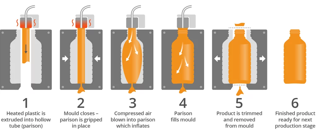
Image taken from Robinson.
3 types of Blow moulding process are,
- Extrusion Blow Moulding.
- Injection Blow Moulding.
- Injection Stretch Moulding.
-
Compression Moulding
Compression moulding process is a cheap moulding method as compared to the injection and transfer moulding methods. It is a high pressure forming process in which the molten plastic material is compressed directly into a hollow mould, with the help of heat and pressure to confirm the shape of the mould.
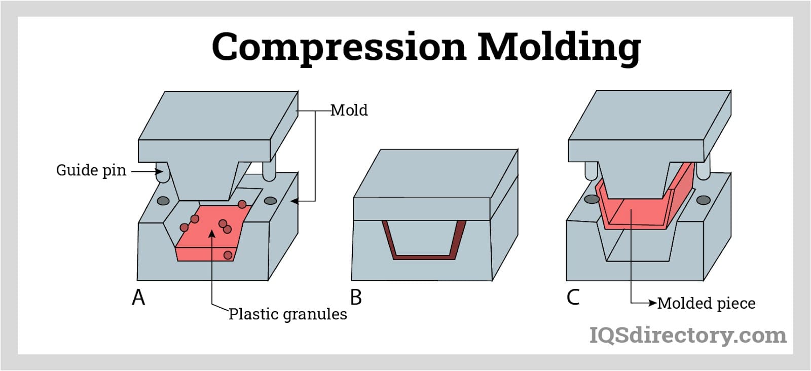
Image taken from Industrial Quick Search. -
Extrusion Moulding
Extrusion moulding is defined as the moulding process which is used for manufacturing the moulding article with the help of die or thermoplastic material. In this the particle is liquified and forced through a die, and after this a long tube like shape is formed. For example- tubes, rods, strips, insulated electric cables etc.
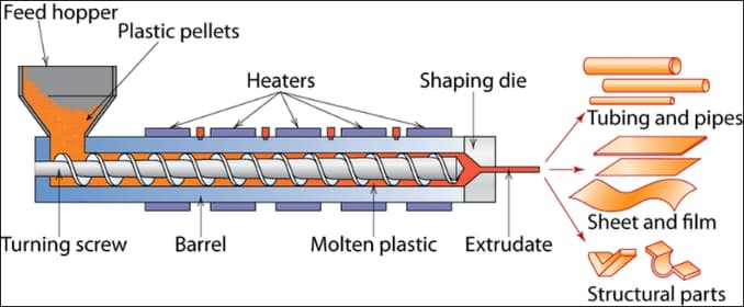
Image taken from Wanhan Plastic. -
Injection Moulding
This is the most common, successful and widely used moulding method to create plastic products. In this method thermoplastic material is powdered or granular form is compressed in a pressure chamber. In this the material is compressed with the help of plunger or reciprocating screw. Then compressed material forced among the nozzle to a cold mould having cavity of desired shape.
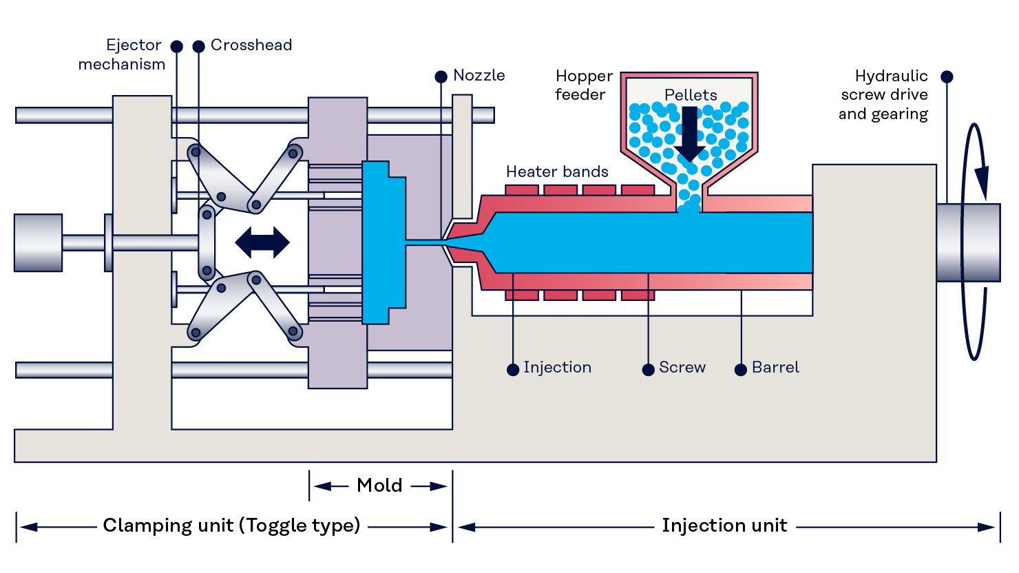
Image taken from Kuraray.
Casting
Casting is the act of pouring liquid material into the cavity of a mold. After a period of time, this liquid will cure via chemical reaction or cooling. The solidified part is also known as a casting, which is ejected or broken out of the mold to complete the process. Casting materials are usually metals or various cold setting materials that cure after mixing two or more components together
Individual Assignment
Design
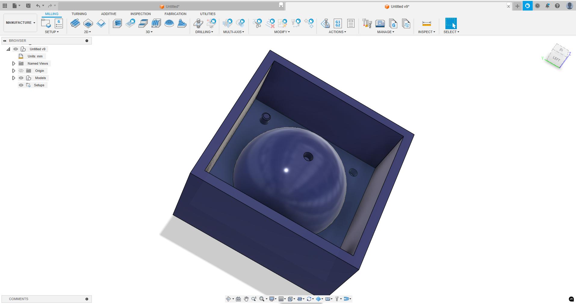
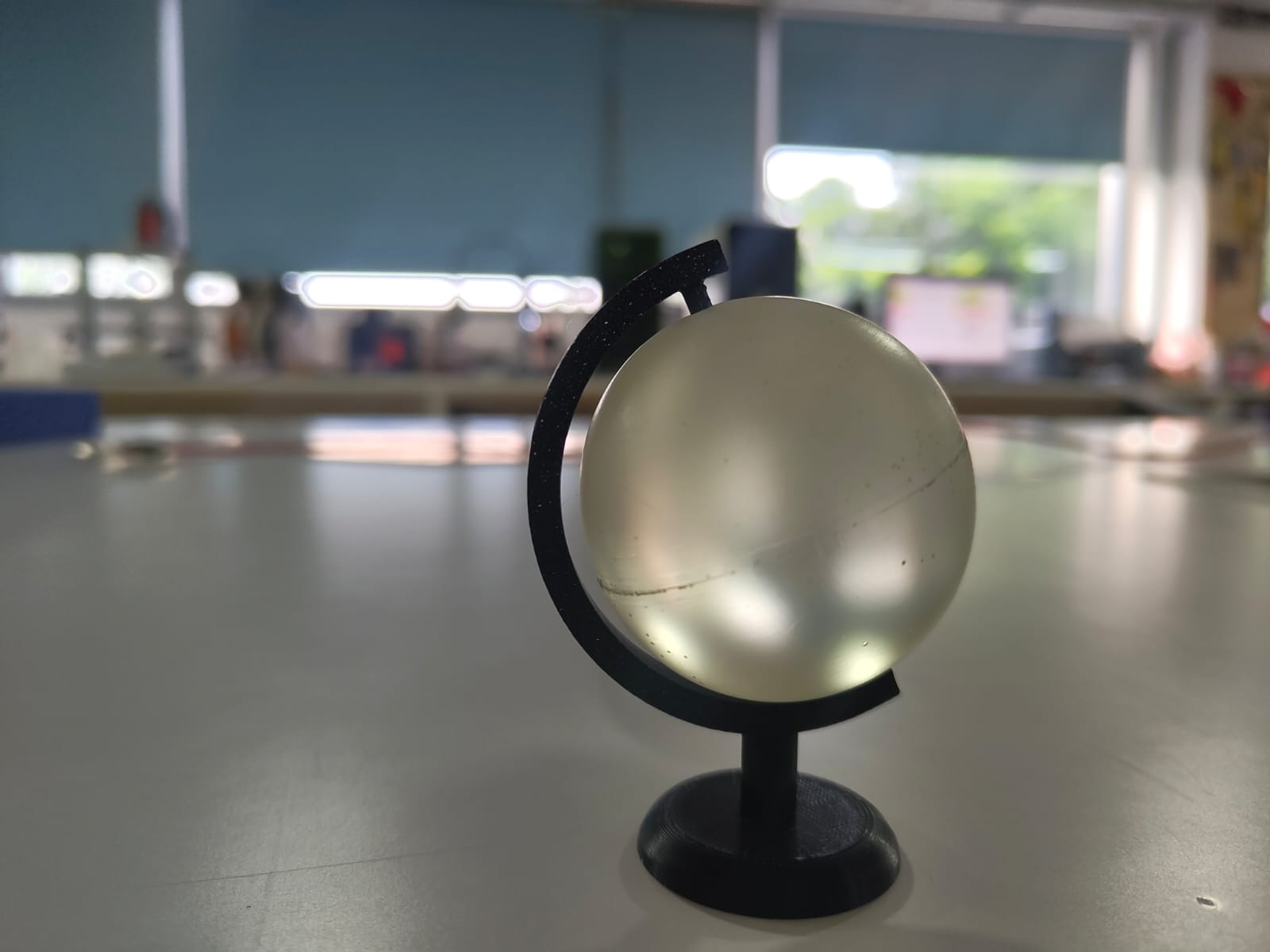
In this week i want to make a mould and cast the design using that mould. So I designed the mould in Fusion 360. I tried to make a globe in which the spherical part was going to be casted and the stand was 3D printed.
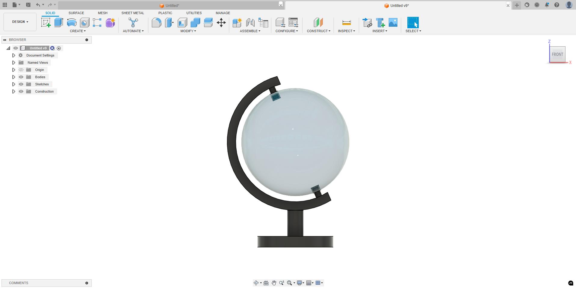
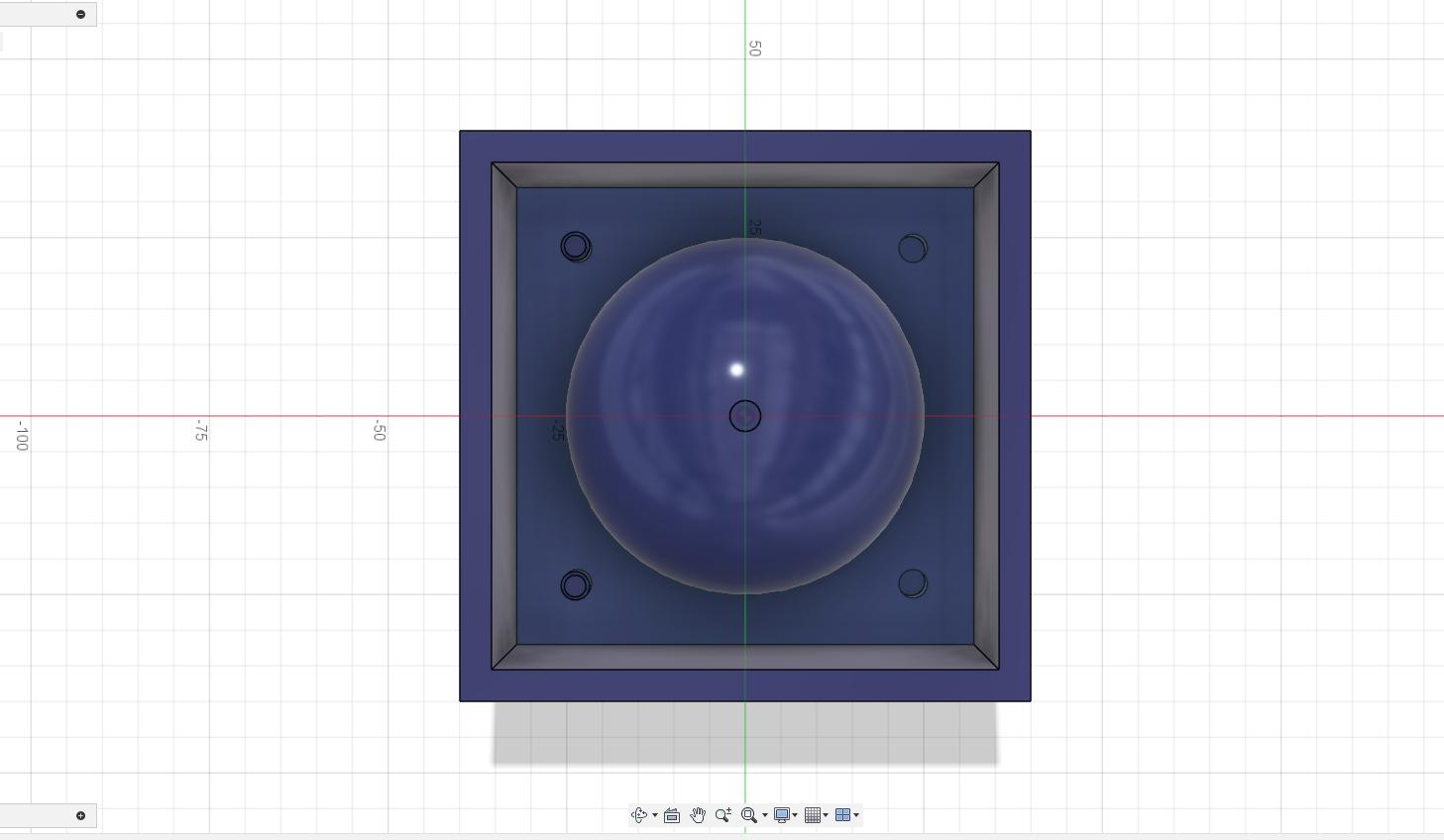
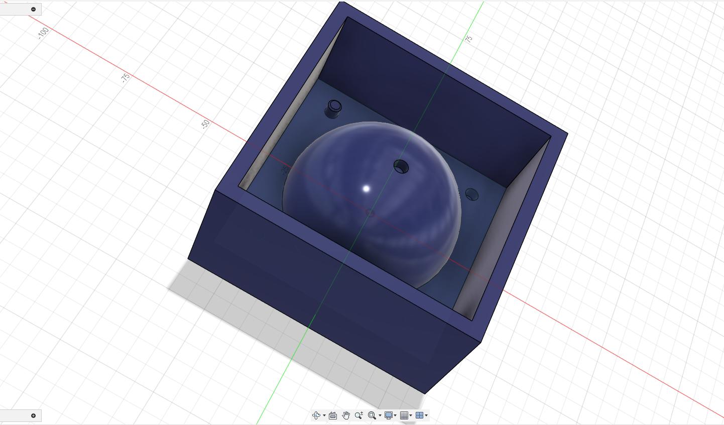
So the sphere was cut into 2 pieces and made its mould in fusion 360. As it was a sphere and symmetrical only 1 side mould needed to be made and by casting it twice the other part can also be obtained.
 |
 |
CAM
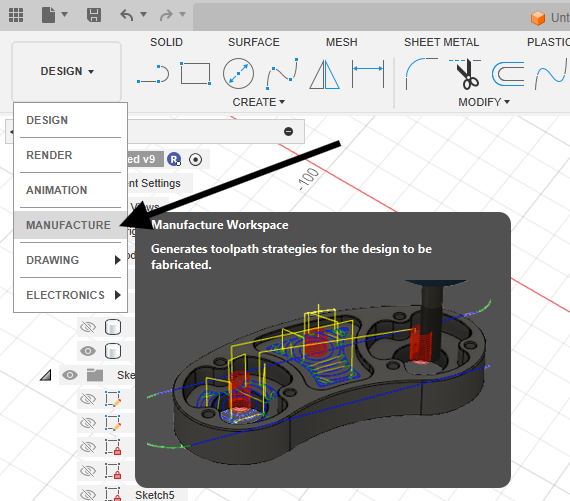
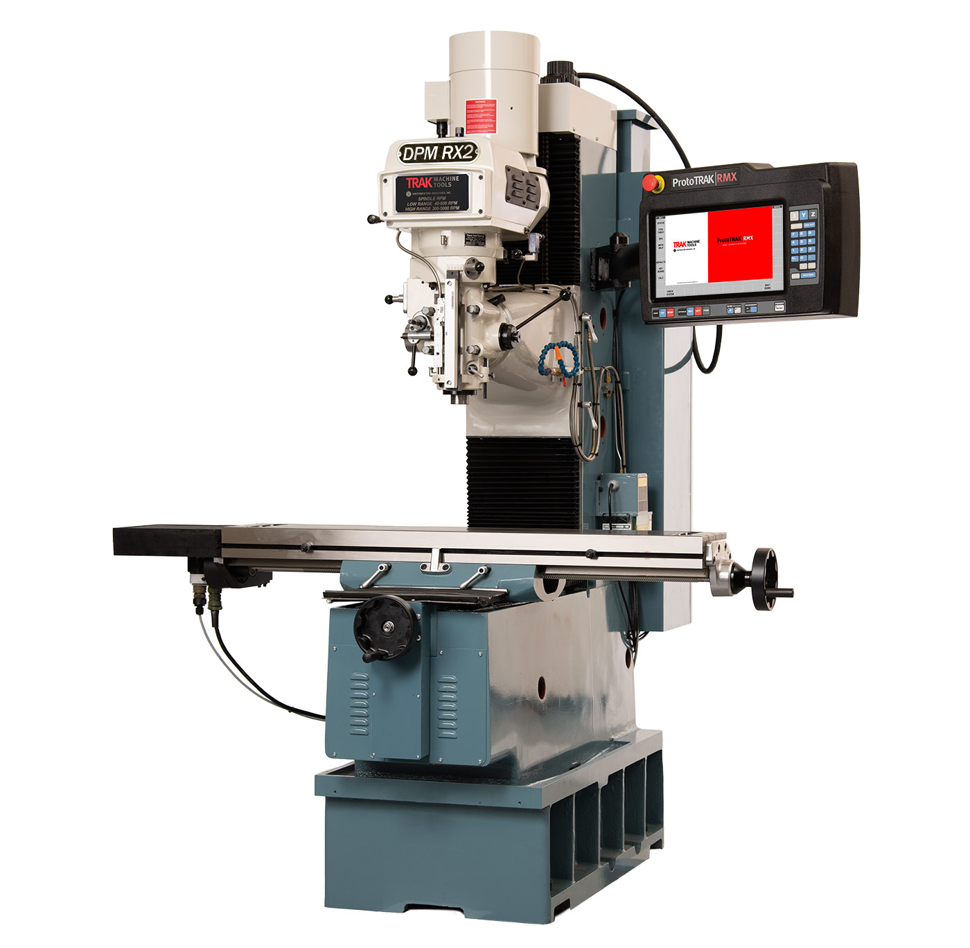
I planned to make the mould in the ProtoTrak DPM RX2 milling machine in our Super Fablab. To make it in the machine I needed to generate the G Codes for it. I used Fusion 360 for Computer Aided Manufacturing (CAM). The CAM procedures were listed below,
Initially switch from the Design workspace to Manufacturing workspace.
 |
 |
-
Initially specify the stock material size of the model.
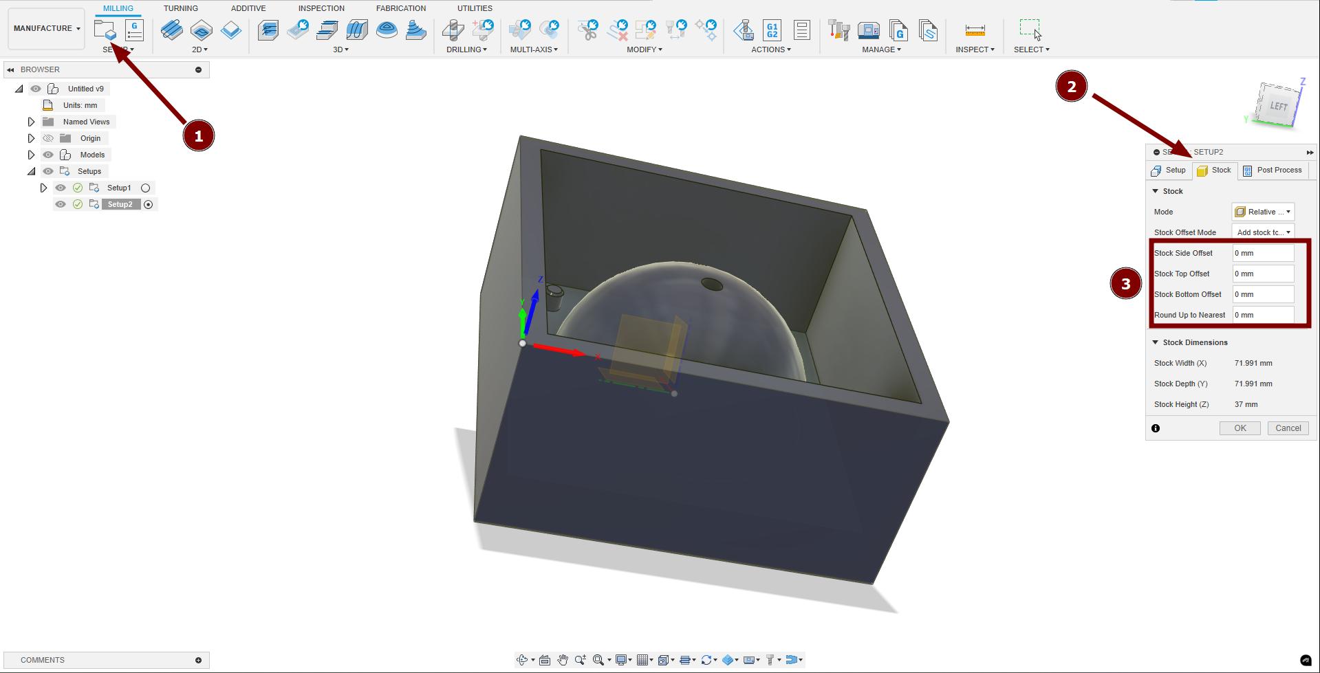
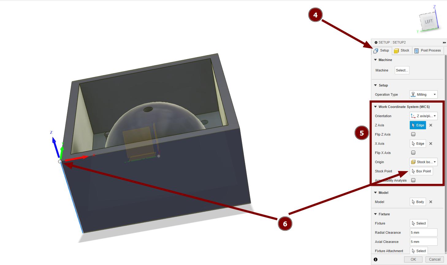
Select the stock setup marked as 1. Specify the size of stock in 3 of section 2. In my case I designed the mould exactly the size of the stock. So the side offset and top offset values were set as 0. Then go to the set up section marked as 4 and specify any 2 of the axis of the design. In my case I selected Z axis and X axis. This was not set exactly like the origin of the fusion 360 but as the axis we needed as Z and X were selected accordingly. Which is marked as 5. Lastly specify the origin of the work piece by using the box point option and I selected as the bottom left corner as my origin which is marked as 6. After specifying the stock parameters click OK.
-
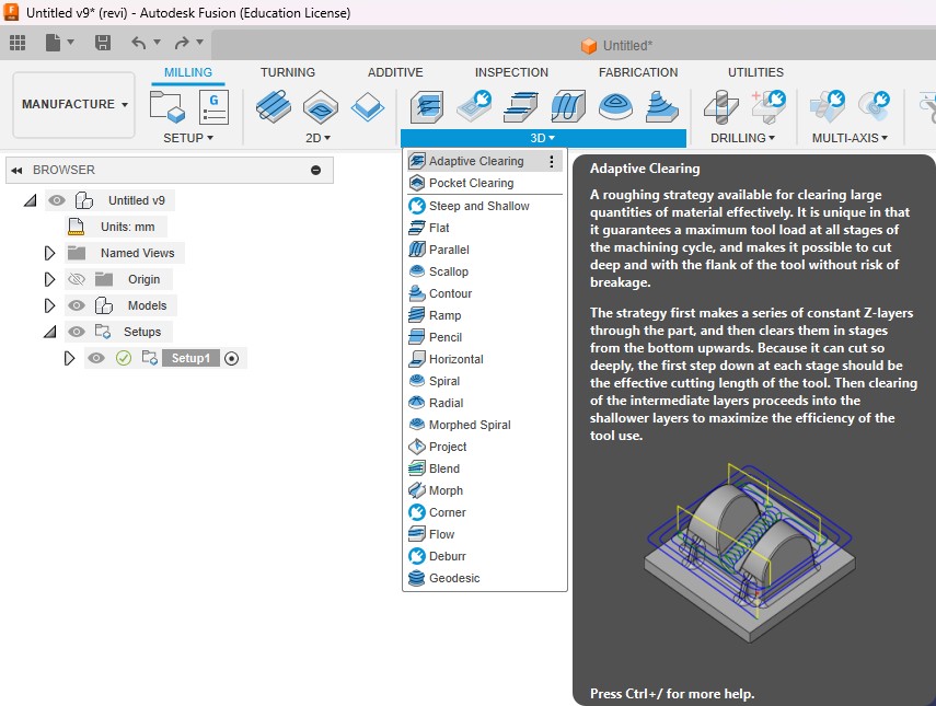
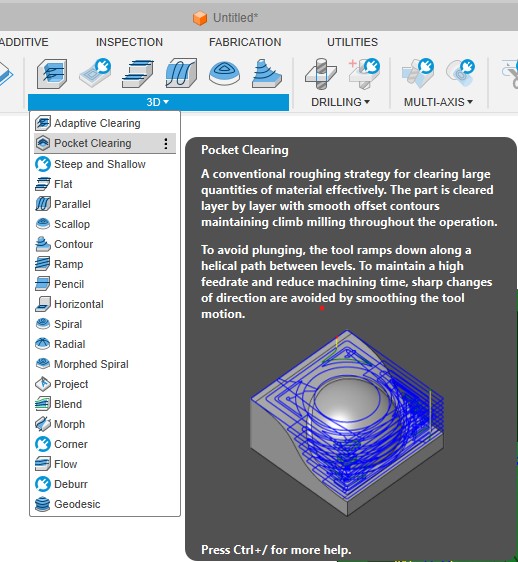
Initially I needed to remove maximum amount of material from the stock. For that I selected the 3D adaptive clearing toolpath.
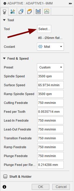
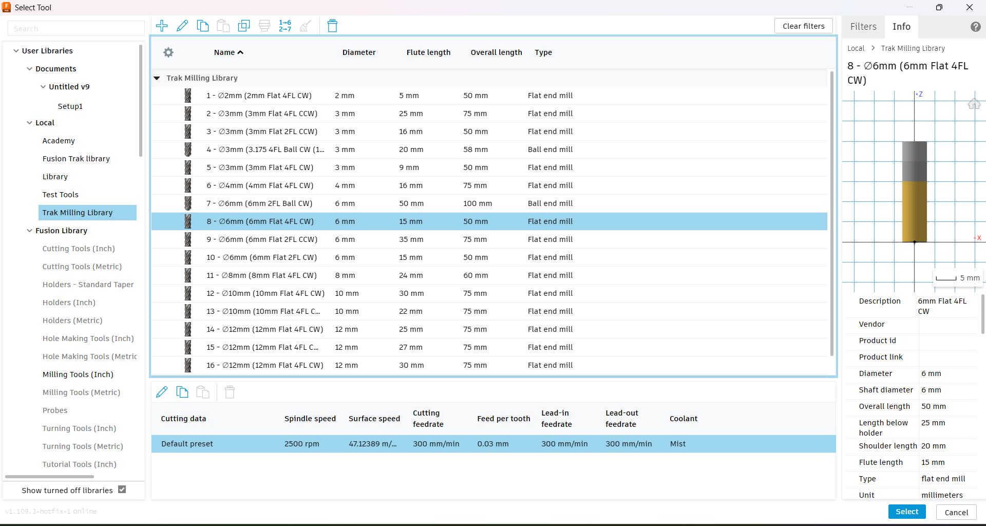
Selected 6mm tool gave the parameters as shown in the image.
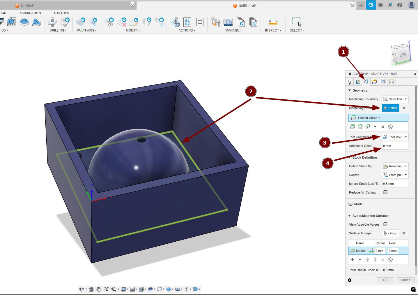
In geometry marked as 1, specify the machining boundary marked as 2, select the tool containment as tool inside boundary marked as 3 and specify any additional offset needed for boundary.
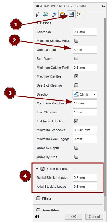
In passes marked as 1, I changed the optimal load as 3mm marked as 2, Maximum roughing stepdown as 10mm marked as 3 and enabled the stock to leave option and set both the Radial and Axial stock as 0.5mm marked as 4.
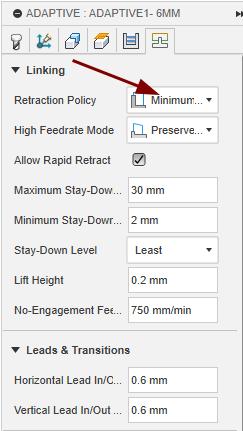
In linking, changed the Retraction policy to Minimum retraction.
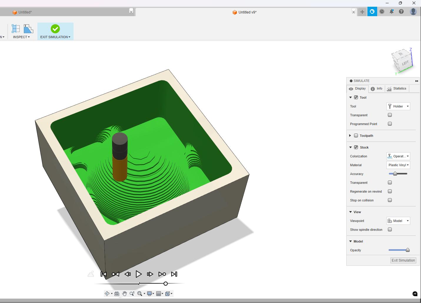
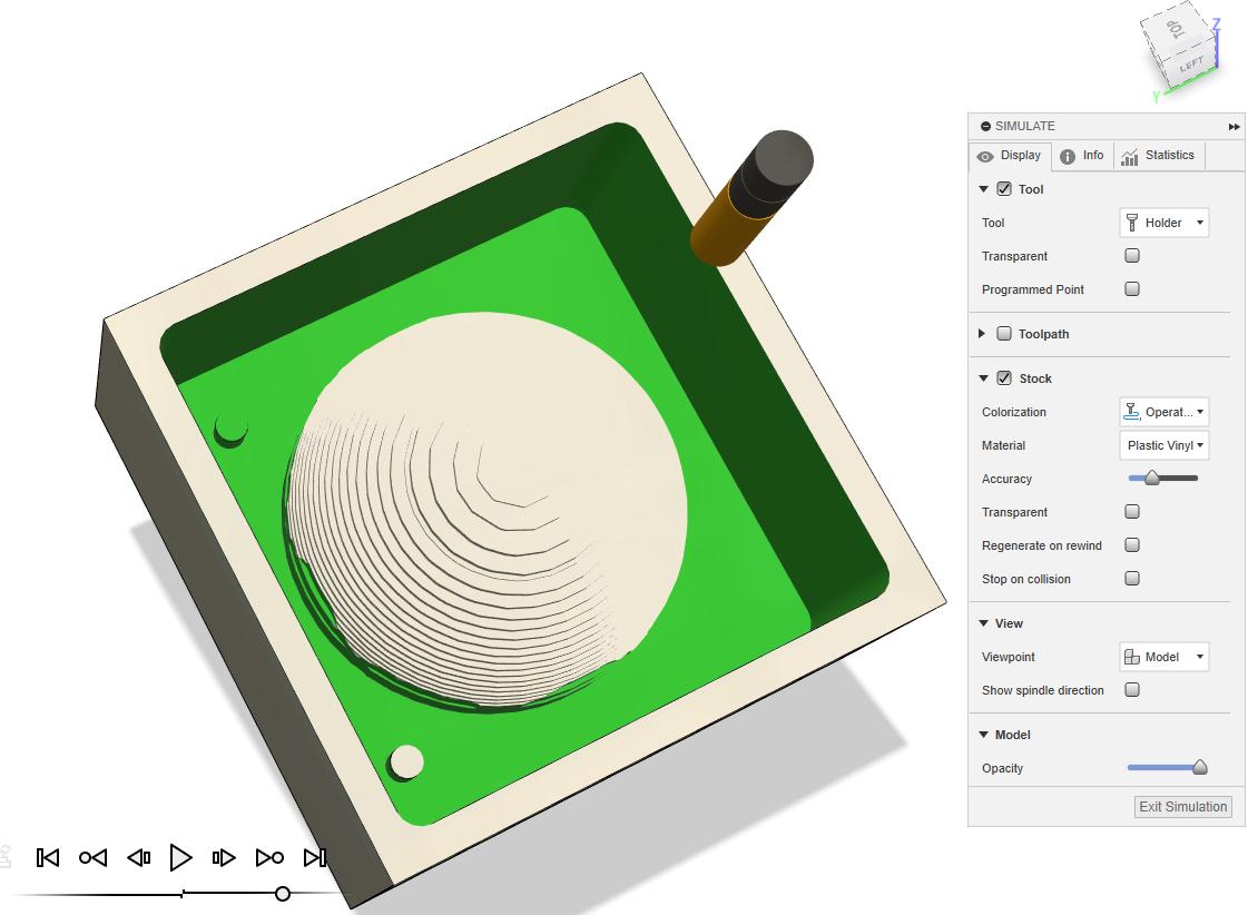
Simulate the toolpath to see how much amount os material was removed from the stock material.
-
To remove the stock removed byt the adaptive clearing option also to remove the 0.5mm stock kept by the previous operation I used 3D pocket clearing. kept the 0.5mm stock on my model and removed only from other areas.
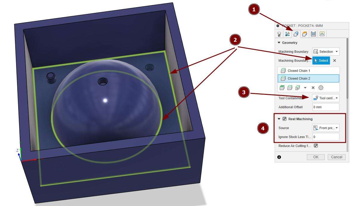
I used the same tool with same parameters here as well. In geometry marked as 1. I selected the boundary from where the material was needed to be removed as marked as 2. changed the Tool containment as tool inside boundary as marked as 3 (In image it shown as tool centre of boundary and it was a mistake). Enabled the Rest machining option to avoid milling in the already milled areas as marked as 4.
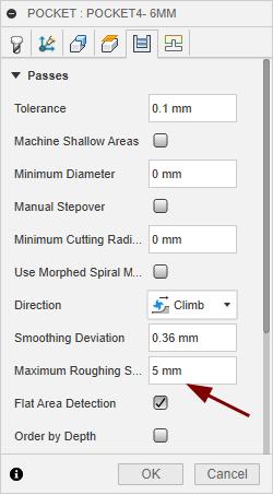
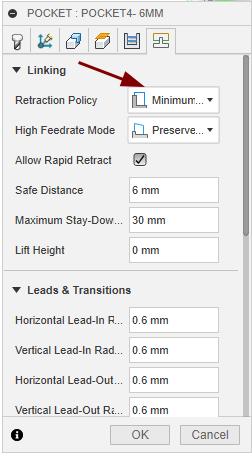
In Passes, changed the maximum roughing stepdown to 5mm and in linking, Retraction policy was set to minimum retraction.
Simulated to see the result after the pocket toolpath.
-
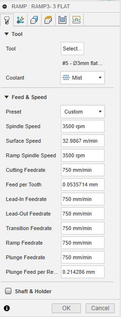
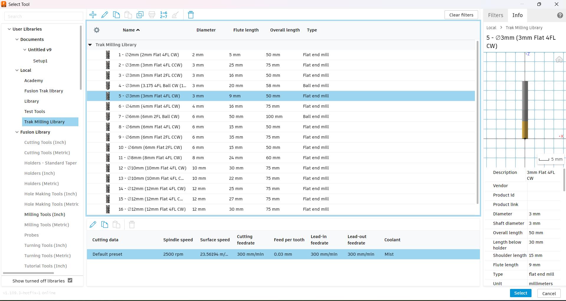
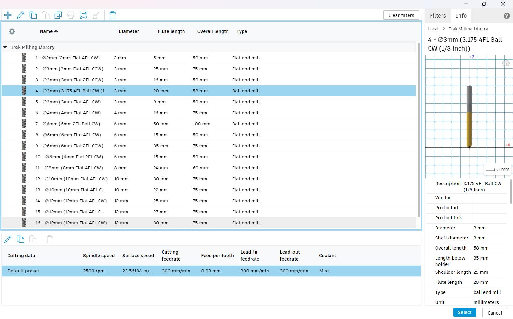
The pin I given was only 4 mm diameter so I needed to use the 3 mm Flat 4 Flute endmill to get the pin as well as the hole above the sphere. For this I choose the Ramp toolpath.
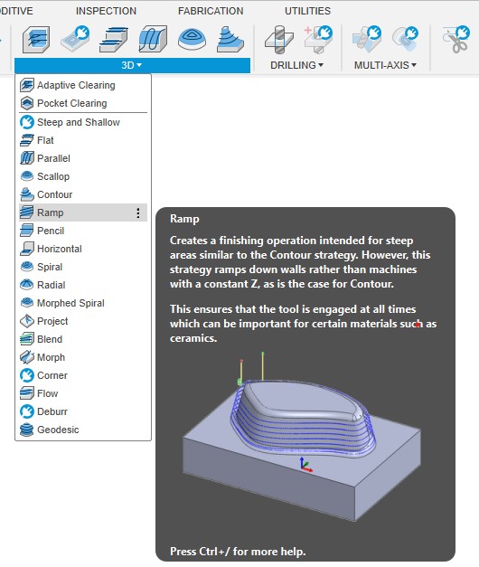
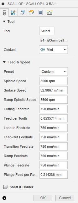
Selected 3mm tool and the used the parameters as shown in the image,
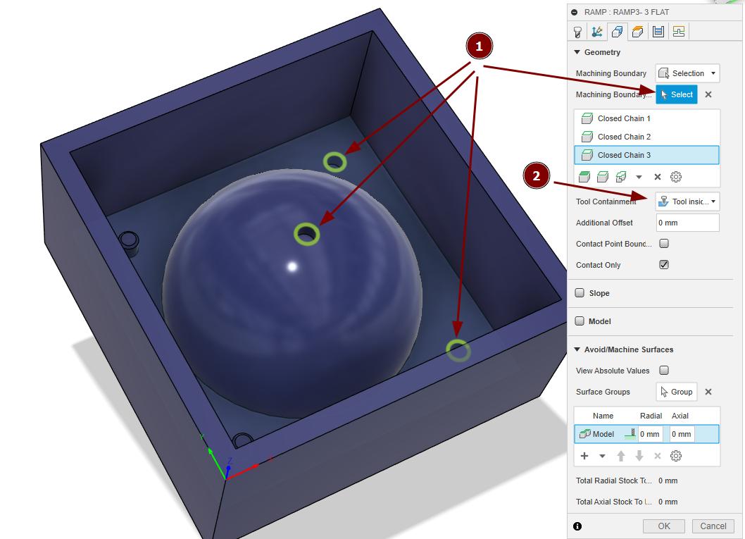
Specified the machining boundaries and changed the tool containment to tool inside boundary.
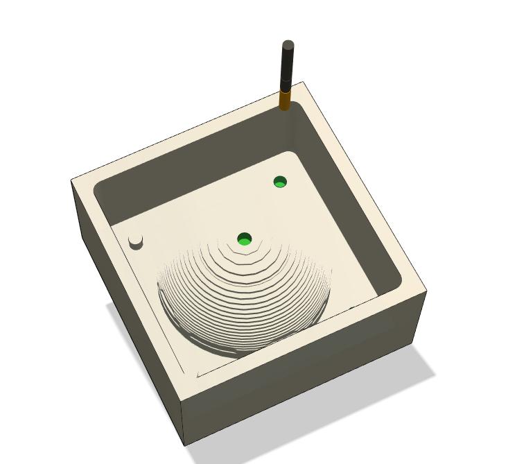
After ramp the result looks like this,
-
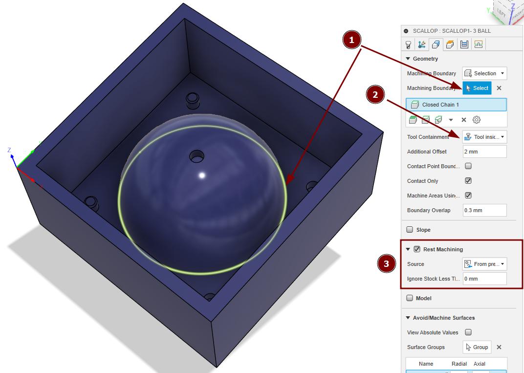
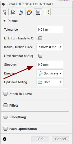
Finally for finishing I used the Scallop toolpath, 3.175mm 4 flute ball endmill was used here.
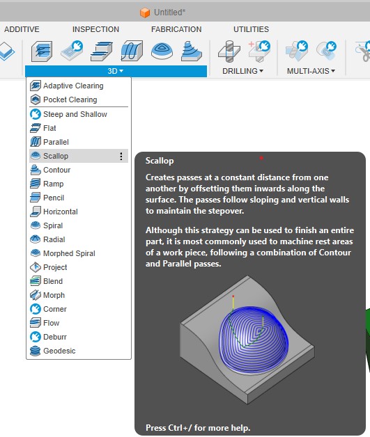
In geometry specified the machining boundary marked as 1. In tool containment select it to tool inside boundary and an additional offset of -3mm was also given (wrongly shown in image) to remove the complete material marked as 2. Also enabled the rest machining marked as 3. Also in passes changed the stepover to 0.2mm.
-
After creating all the toolpaths and verifying it I post processed the toolpsths for our milling machine. The steps for it is listed below,
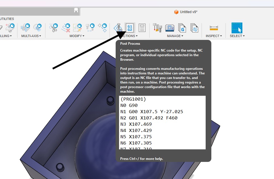
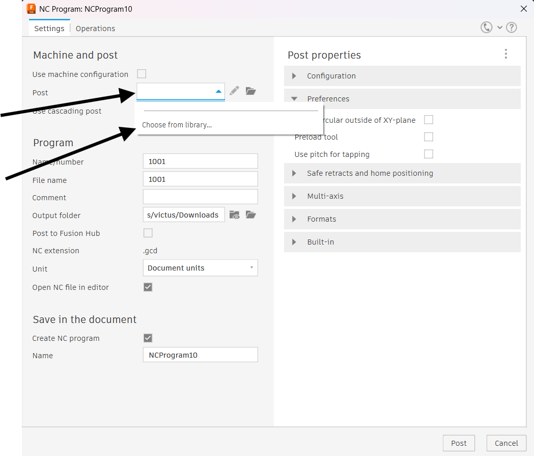
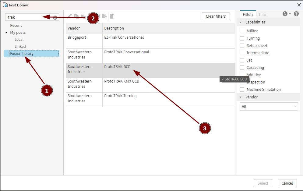
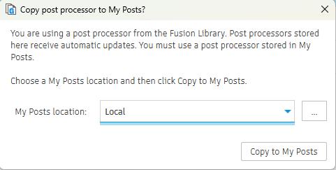
When clicking post process a window opens and initially I selected our machine from the fusion 360 library to post the tool paths for our machine. For that select the post option marked and a drop down appears showing choose from library. Select that option. Select the fusion library marked as 1 search the name of the machine marked as 2 select the exact model of the machine. Our machine is marked as 3. Select the post location and copy post.
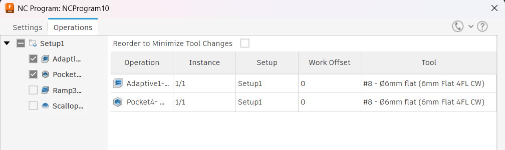
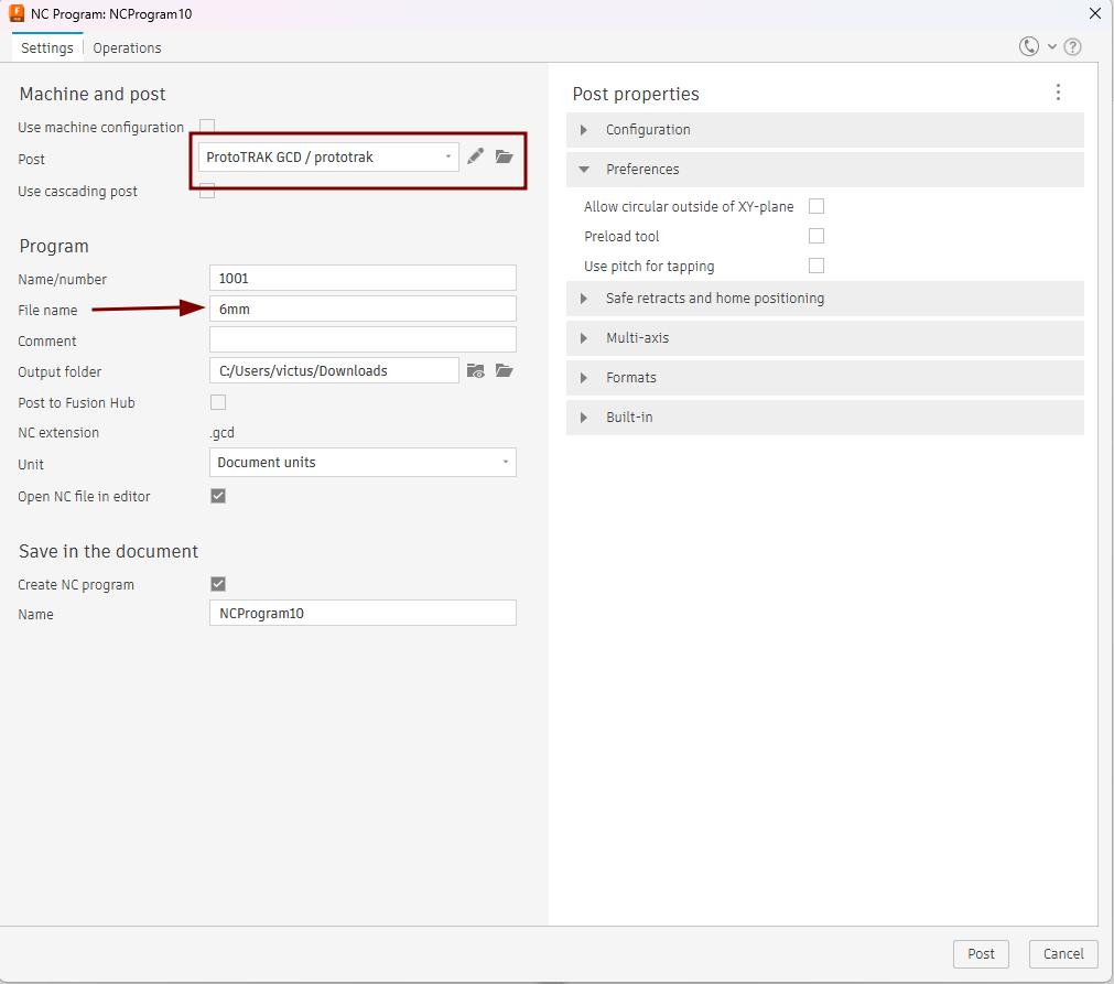
The machine was added into the post and I changed the name of the program to 6mm as my first program uses 6mm endmill. You can use any name there. Then in operations I selected Adaptive and pocket as they both uses 6mm endmill. Again go back to the settings and click post. In output folder we can change the folder location to save the file.
Similarly posted the other 2 toolpaths as well.
These programs then copied in a USB and connected to the machine.
The simulation of the tool path is shown below,
Milling
I already mentoned above that the machine I used was the ProtoTrak DPM RX2milling machine available in the Super Fablab.
Setting up the machine
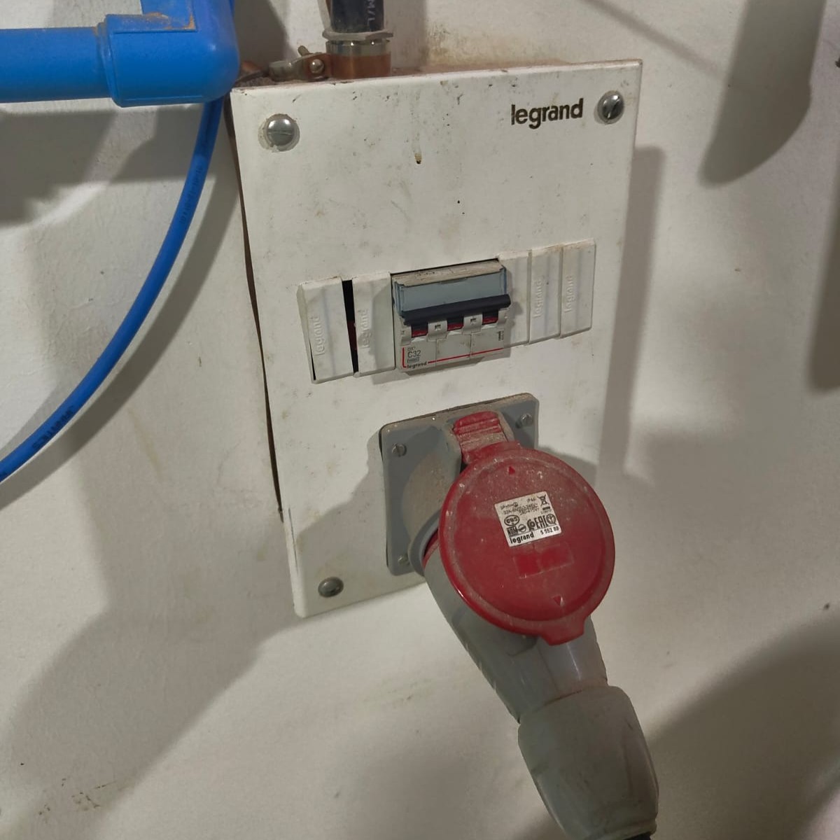
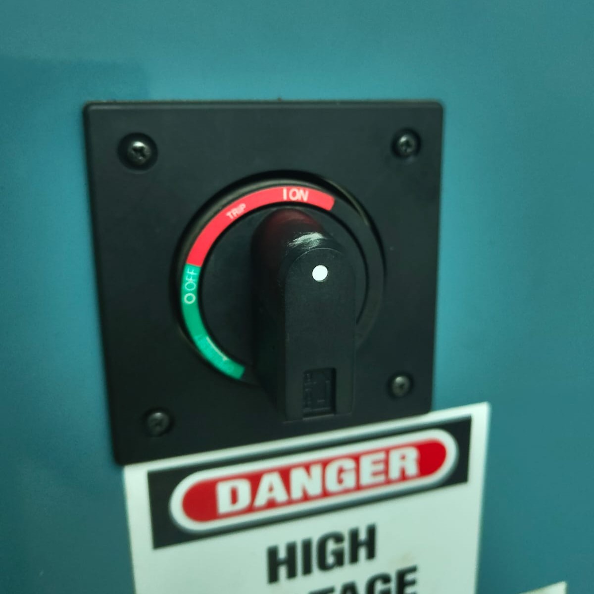
Turn ON the main switch as well as the switch on the back side of the machine.
 |
 |
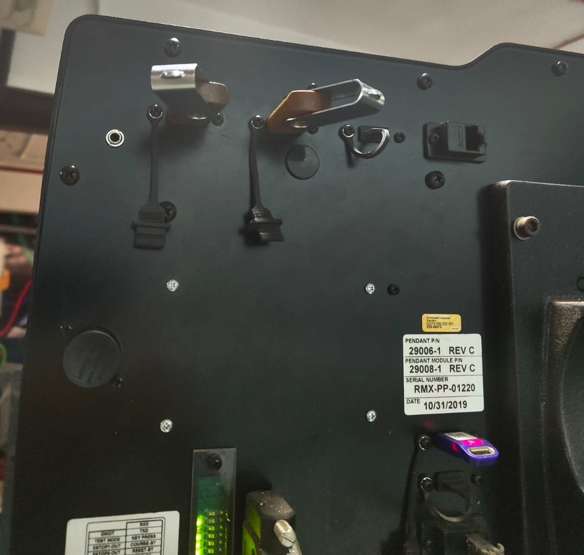
Connect the USB on the back side of the DRO.
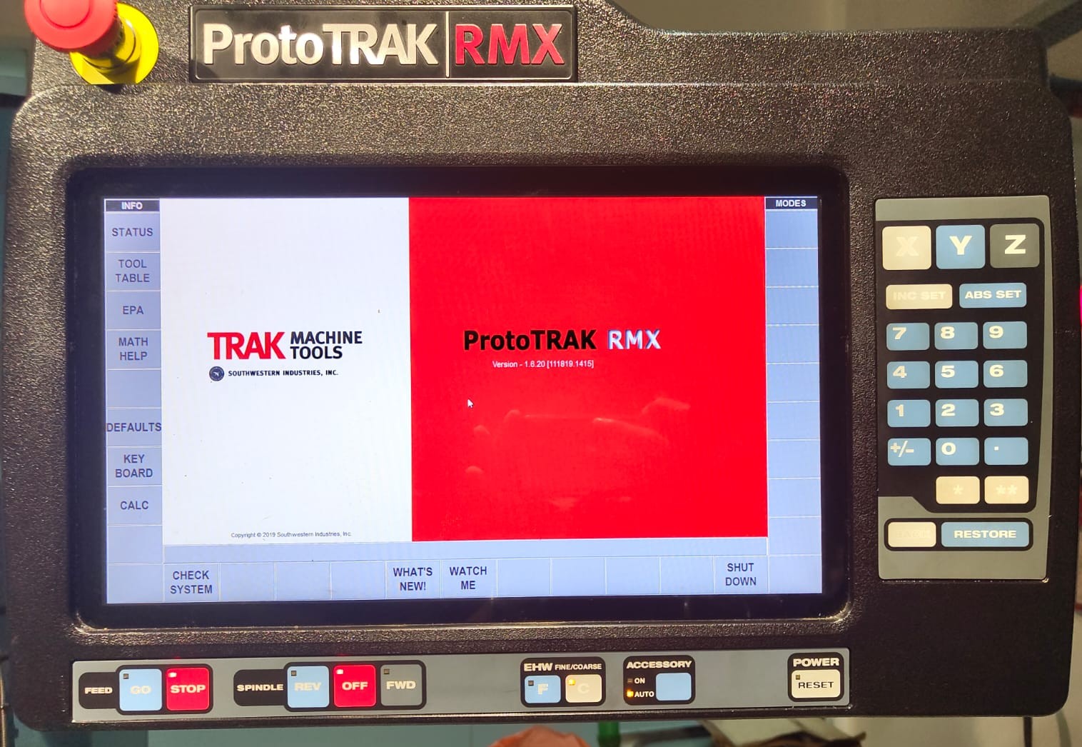
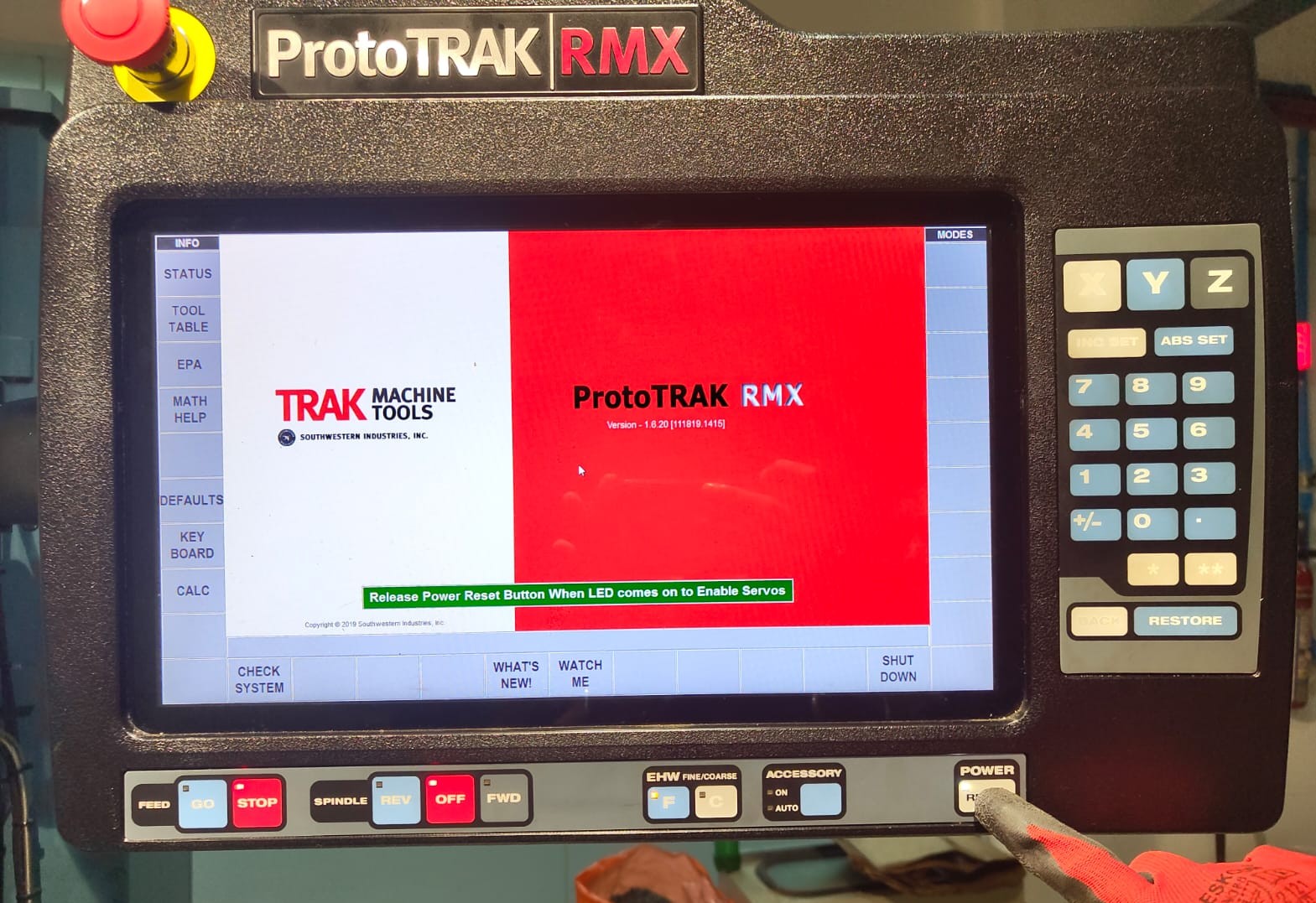
Wait until the below screen appears. Press and hold the Reset button untill a white LED turns ON in the Reset switch. This will enable all the servos of the machine and the lubricant pump pumps the lubricant to all over the machine.
 |
 |
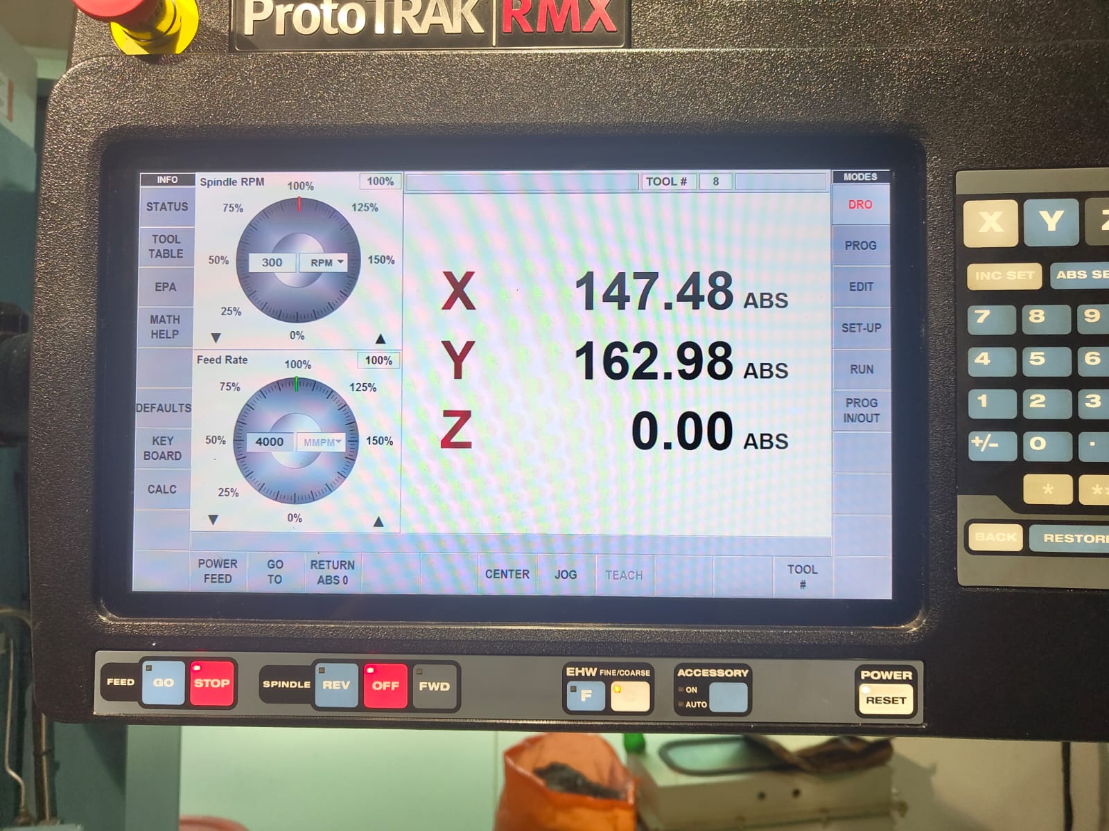
Click CHECK SYSTEM → DRO so that the machine is ready and can be moved manually. In DRO we can move the X and Y axis using the hand wheels and in every modes the hand wheels were disabled.
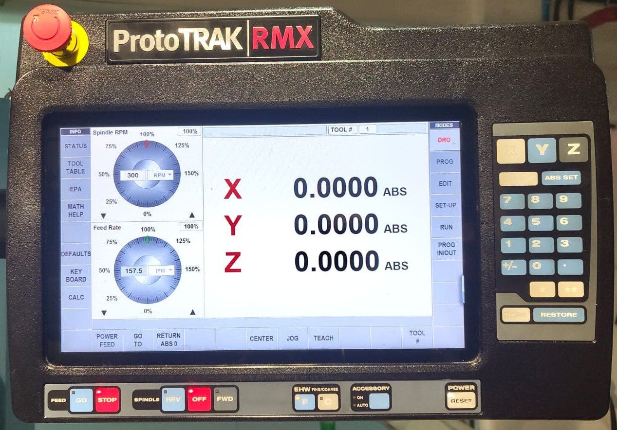
By using the JOG mode we can move the axis manually by the X, Y and Z buttons on the right side. While entering the JOG mode all the axis can be moved on the positive direction. To move the axis in negative direction click the +/- button in the lower right side. one click the axis changes to negative and in next click the axis again changes to positive direction. that is the button is used for toggle the direction of the axis While in the JOG mode.
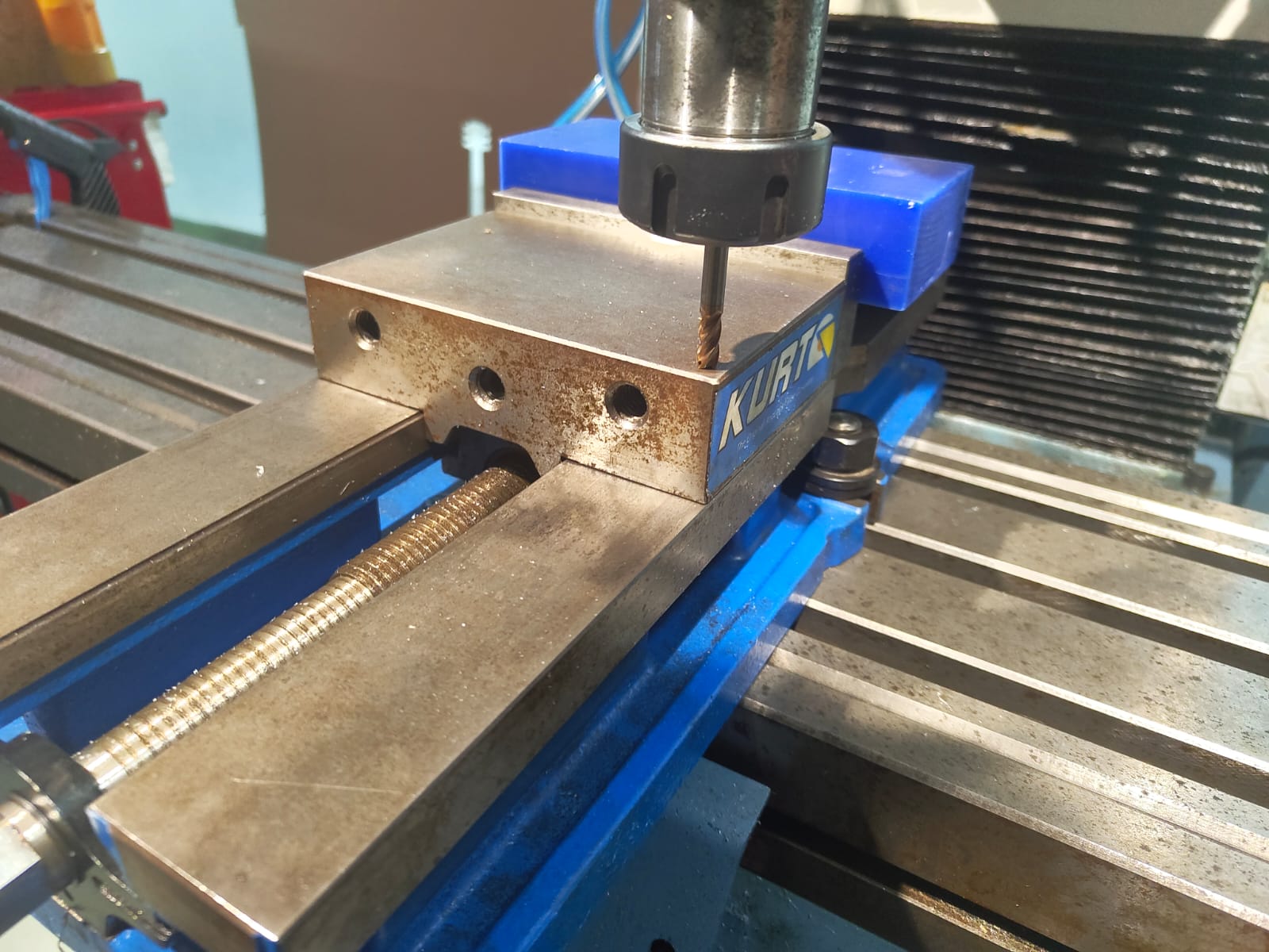
Then clean the vice and load the workpiece on to the vice and using the edge finder zeroed the X and Y axis as per the CAM.
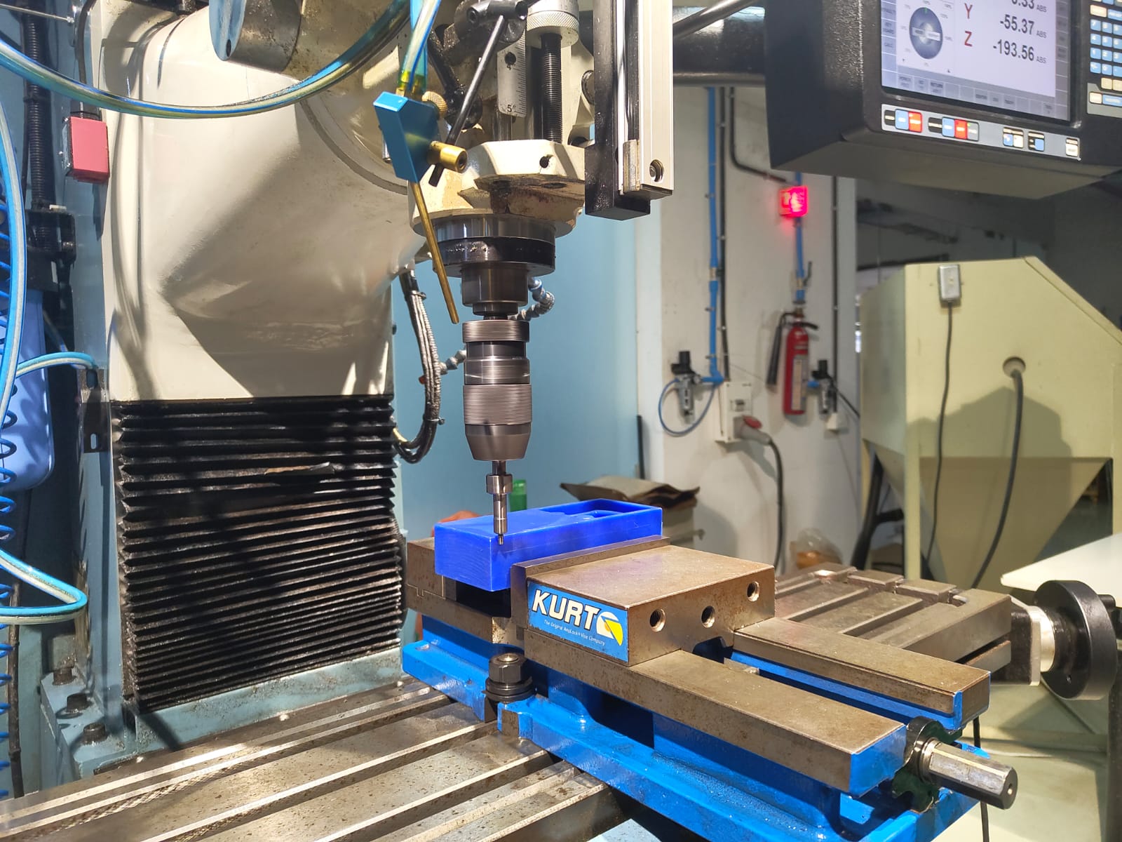
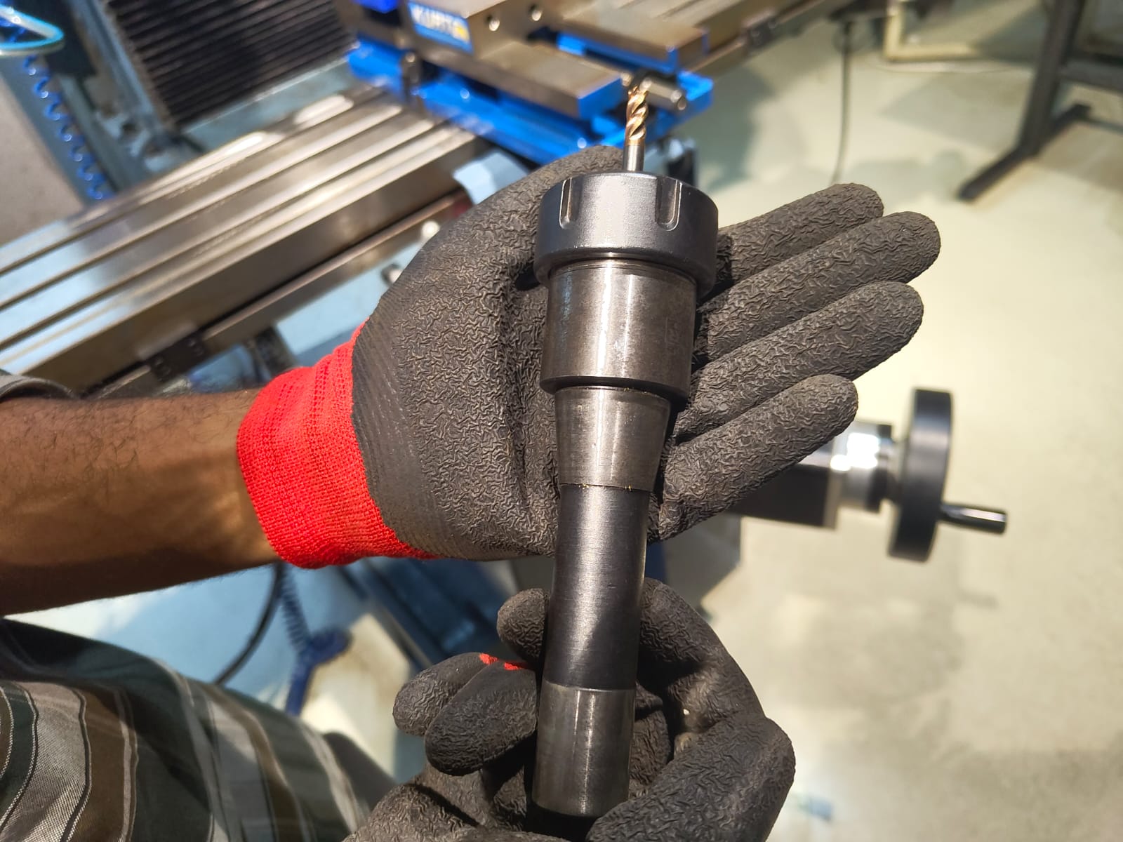
The first tool I needed was 6mm 4flute flat endmill. So I loaded the tool on to the tool holder and clamped it into the machine.
 |
|
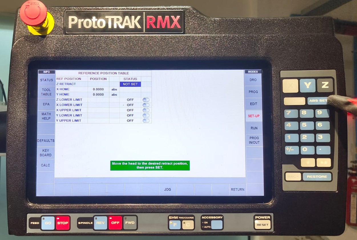
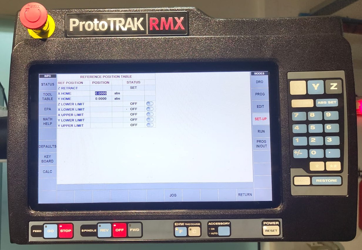
To run the program we needed to set the Z retract height. This is the height from which the program starts and stops. If it is not set the program won't run and show error. Click SET-UP → REF POSN → Z RETRACT. Initially it is shown as NOT SET. move the Z axis to the safe height using JOG mode and press the ABS SET button to set the Z RETRACT height.
 |
 |
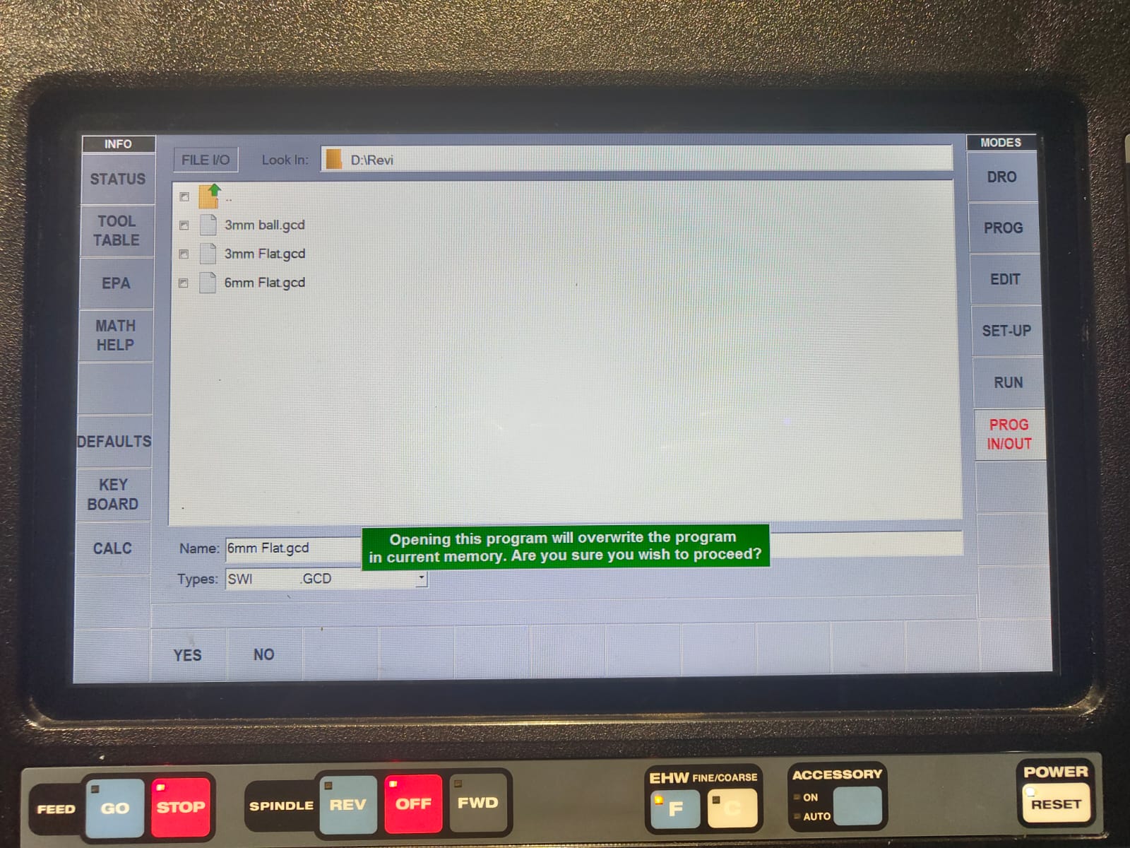
Then I selected the program. For that select PRGM IN/OUT option and locate the program from the USB connected. Click the program and select OPEN and a warning says this will over write the previous program. Click yes to load the program.
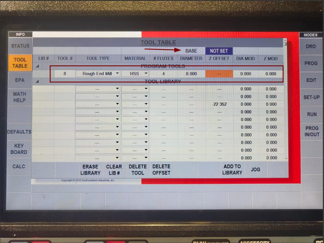
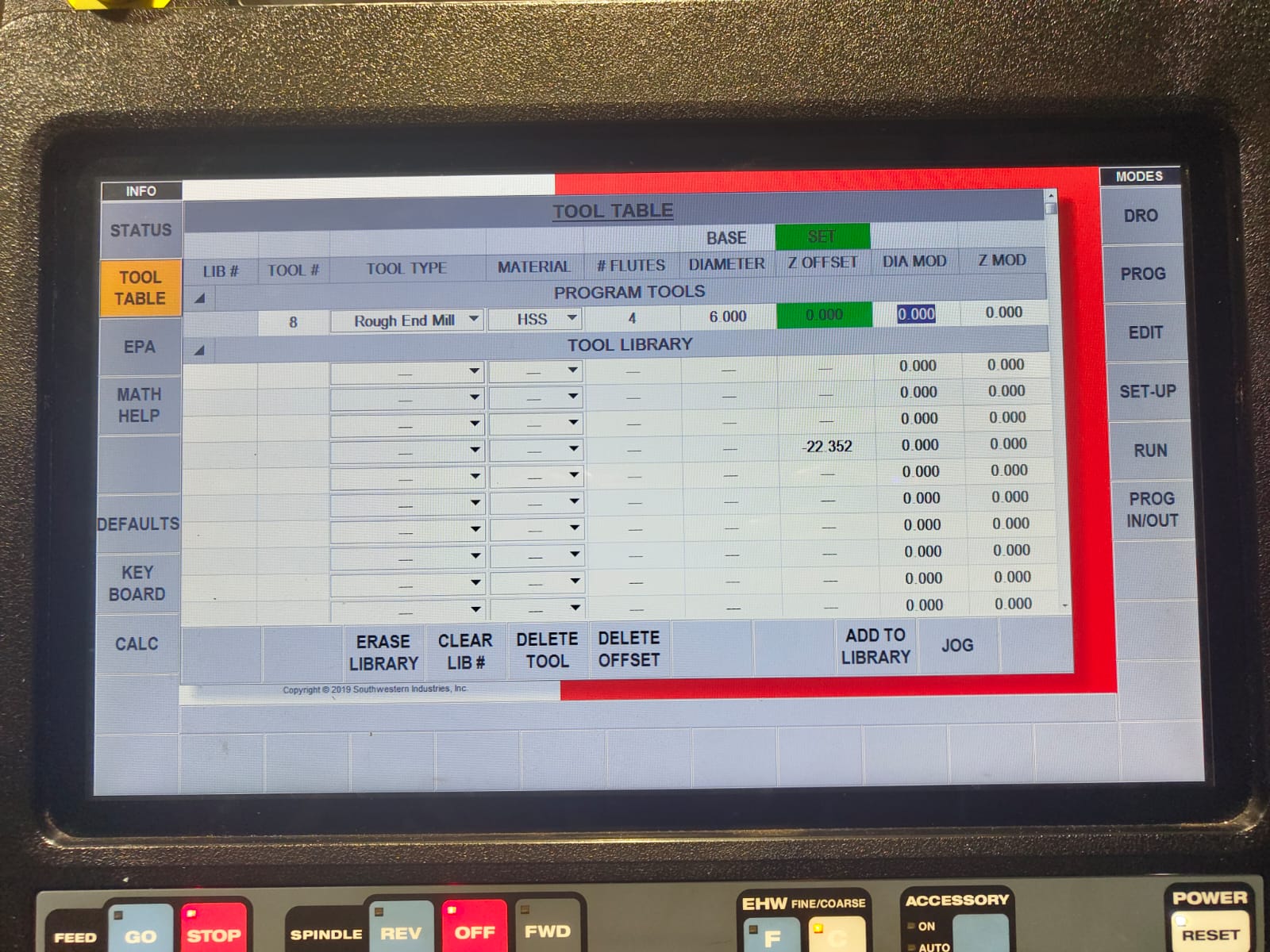
After that in TOOL TABLE I specified the tool parameters and I set the BASE tool offset with the 6mm tool I loaded on the machine. When loading next tool the tool length offset were calculated from this base tool offset. Initially it will show as the base tool was NOT SET. So select that and touth the tool on any point of either the workpiece or the vice. I prefer touching the top of the vice and touched the tool on top of the vice. keeping the tool there the ABS SET is pressed and the base offset was then set. Also click the Z OFFSET and press the ABS SET to set the tool leength offset of the current tool from the base tool. AS the base tool is set with the same tool the difference will be 0.
 |
 |
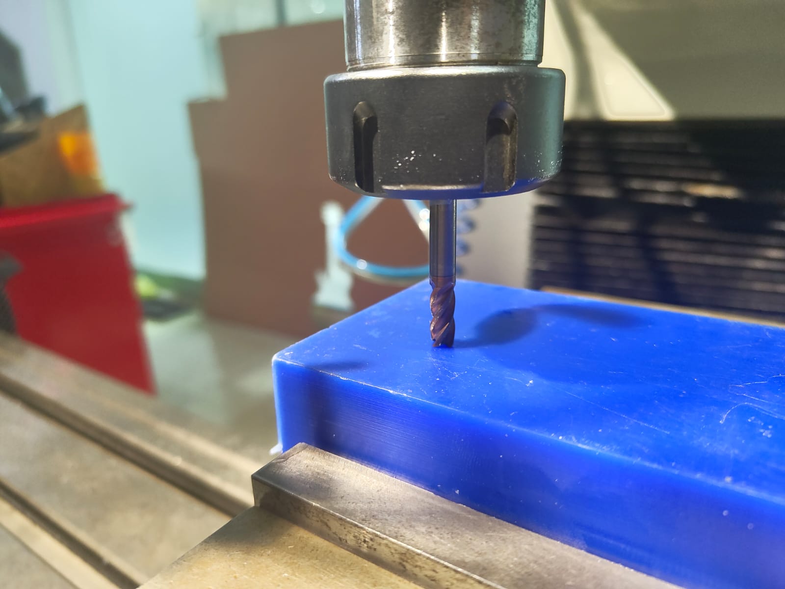
Then I took the Z offset of the work piece by touching the tool on top of the work piece and select the Z button and press ABS SET.
 |
 |
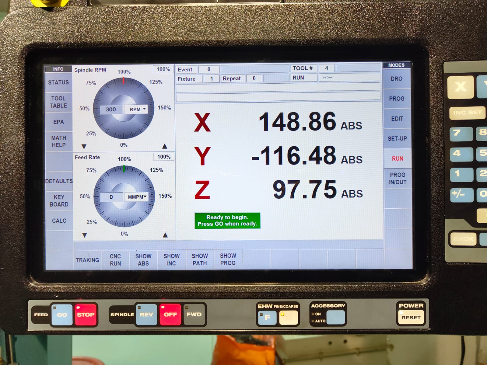
After all these settings I can run the program. For running the program select the RUN option. The program will be checked and START option will be displayed on the bottom. Click START and so many options will be displayed on the bottom. Select TRAKING. TRAKING means we can exicute the program by rotating the hand wheel. The X asis hand wheel can be used for coarse feed and the Y axis hand wheel can be used for fine feed. It is a useful feature to check the program at the start whether the program exicute corectly. Initially the machine goes to the Z retract position and X0 Y0 position and stops. Again I needed to select the TRAKING and turn ON spindle in forward direction because I used the clockwise tool here. To turn ON the spindle in clockwise direction press the FWD button in SPINDLE. Make sure don't rotate the tool in its opposite direction.
 |
 |
If everything works fine press the STOP in FEED and select CNC RUN next to TRAKING and press GO in FEED. And the program starts running.
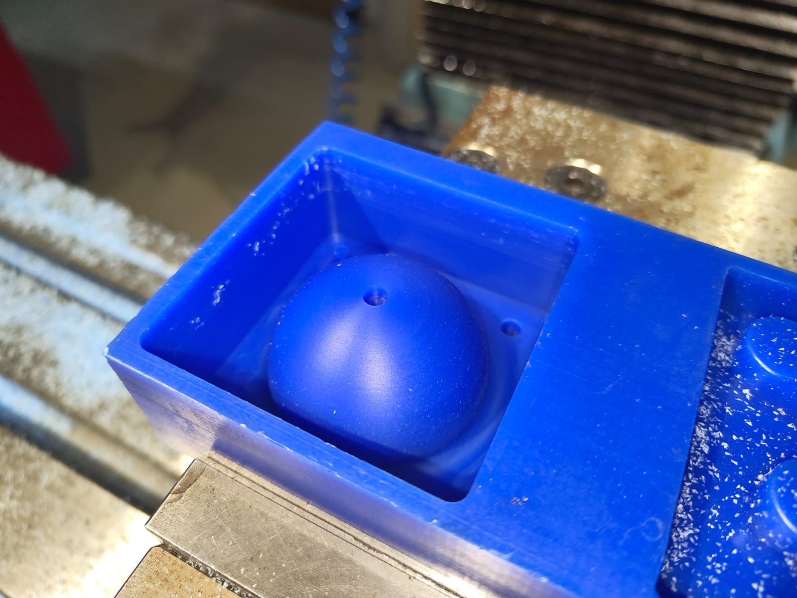
Similarly loaded the other 2 files and machined it. The final output is shown below.
 |
Silicon Mould
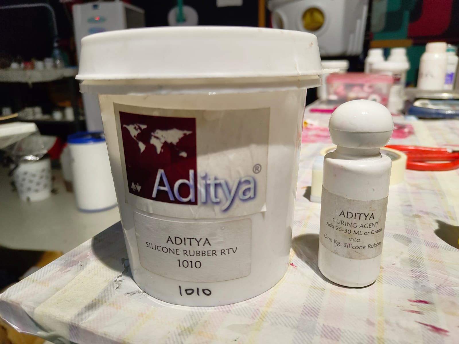
The datasheet fot the Aditya Silicone Rubber RTV – 1010 is here.
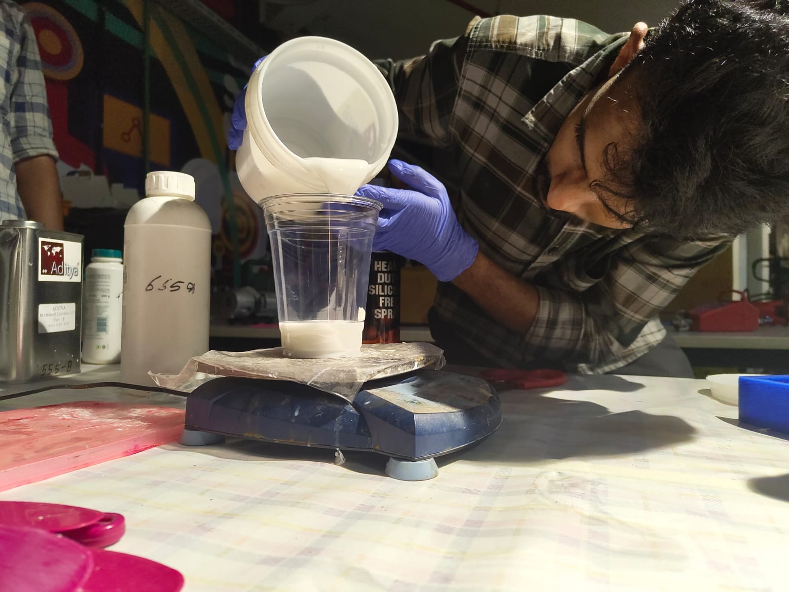
As I am dealing with chemicals I used a well ventillated area for pouring the silicon rubber. I used a latex glove for avoiding the contact it with my hands.
After milling the mould, I needed to make a negative silicon mould of the design. Silicon mould making process I followed is listed below,
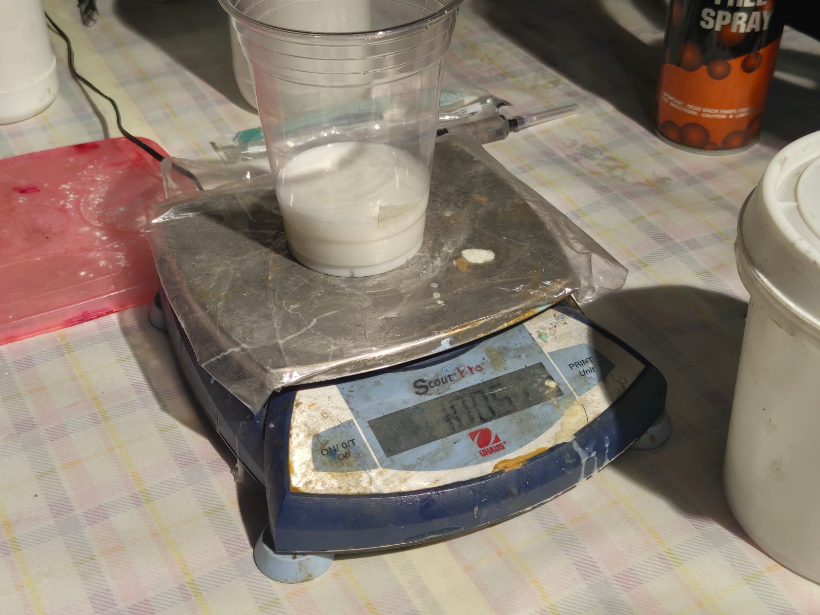
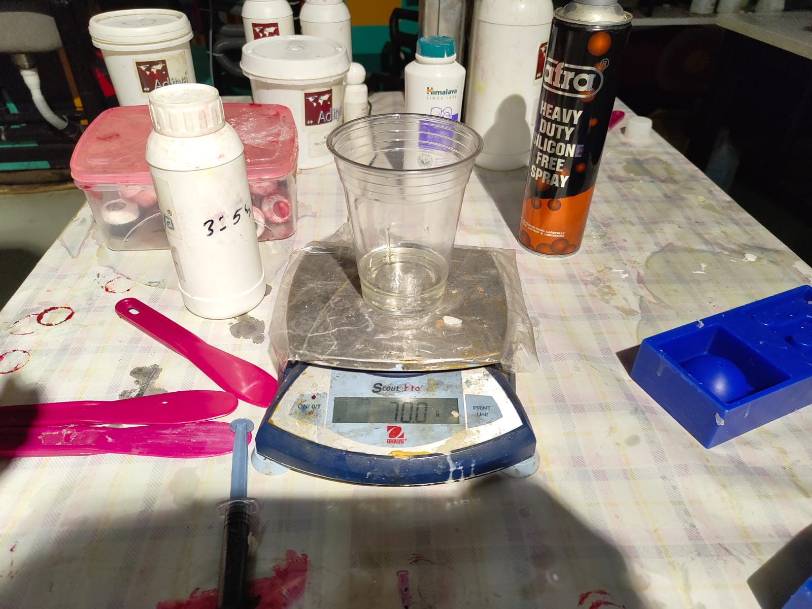
I took a glass almost twice the size of the volume of my mould cavity and a stick to mix it from the inventory. Filled the mould cavity with water and poured it on to the glass to get the exact volume of the mould cavity. I marked the level of the water. As the casting process included lot of chemicals, I used latex gloves for safety.
Then I took the Silicon rubber and its hardner. The ratio of the silicon to hardner was 1000:35 ml.
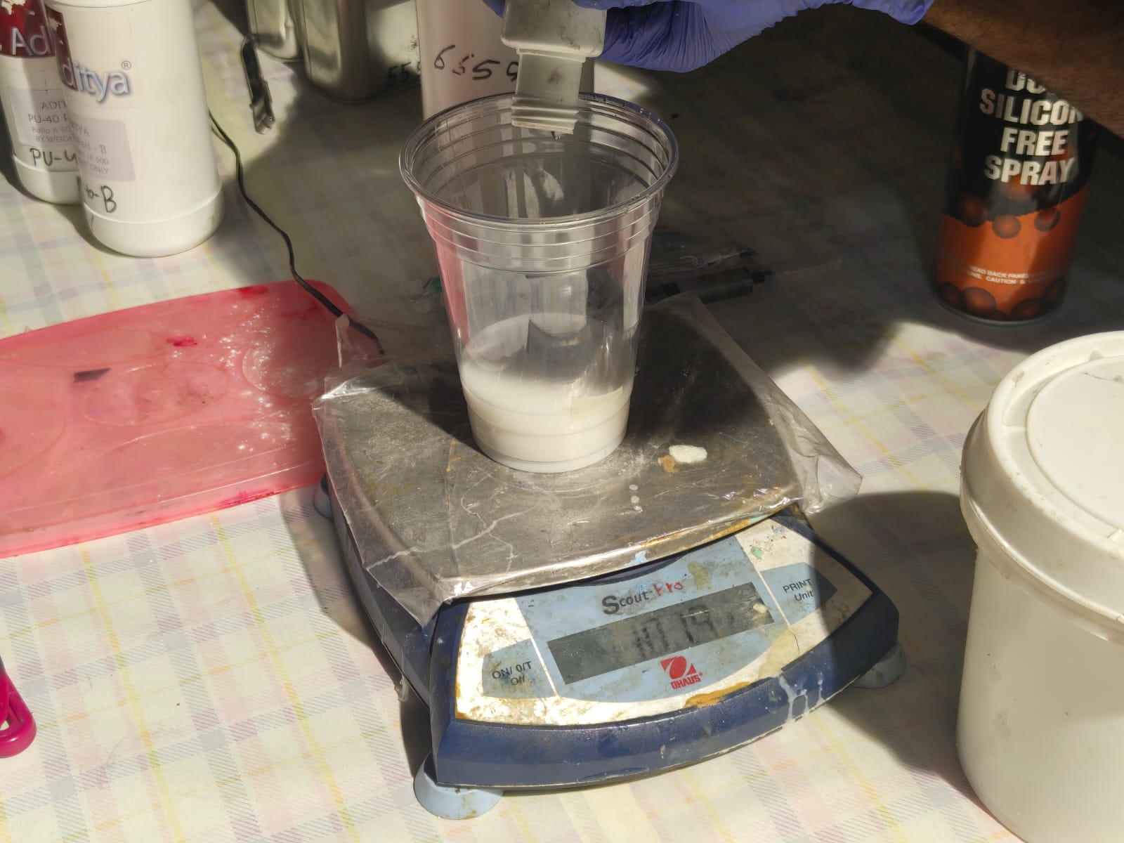
Then I cleaned the water from the glass and placed the glass above a weighing machine eliminated the weight of the glass. I then poured the silicon to the marking and it was 100gm. So as per the ratio I needed to pour 3.5gm of hardner on to the silicon. I add tht as well. and mixed well and placed it in the vacuum chamber to remove the air bubbles inside the silicon.
 |
 |
Adding hardner
 |
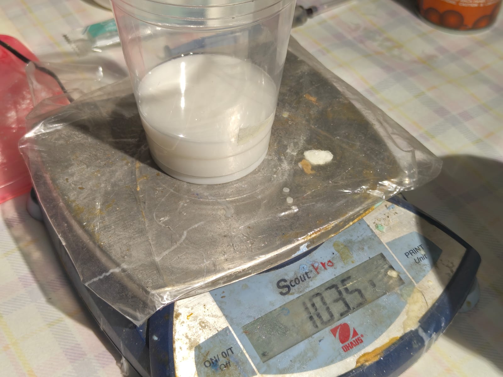 |
Mixed the silicon and the hardner well with the stick.
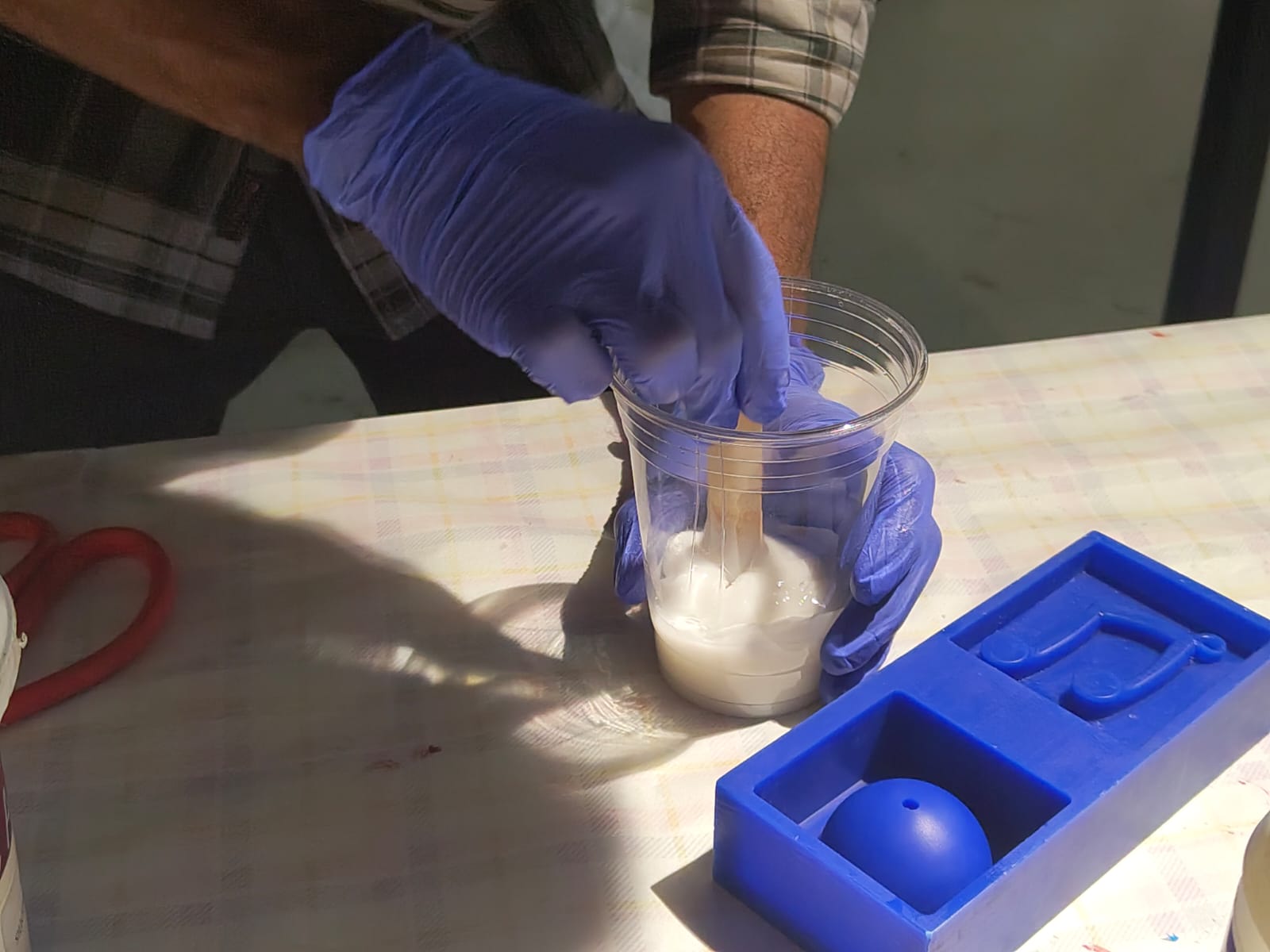
Placed it in the vacuum chamber to remove air bubbles.
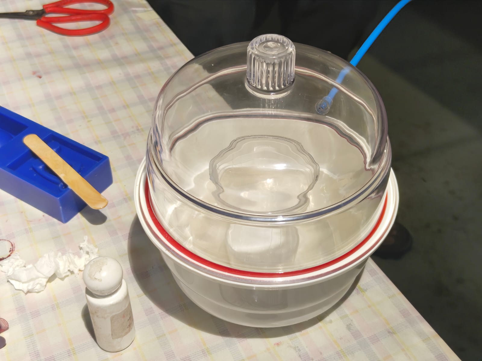 |
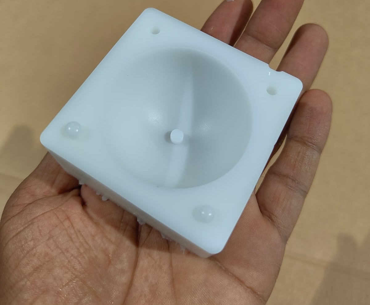
After all the air bubbles were cleared I poured the silicon on to the milled mould. Unfortunately I can't able to pour the silicon neately.
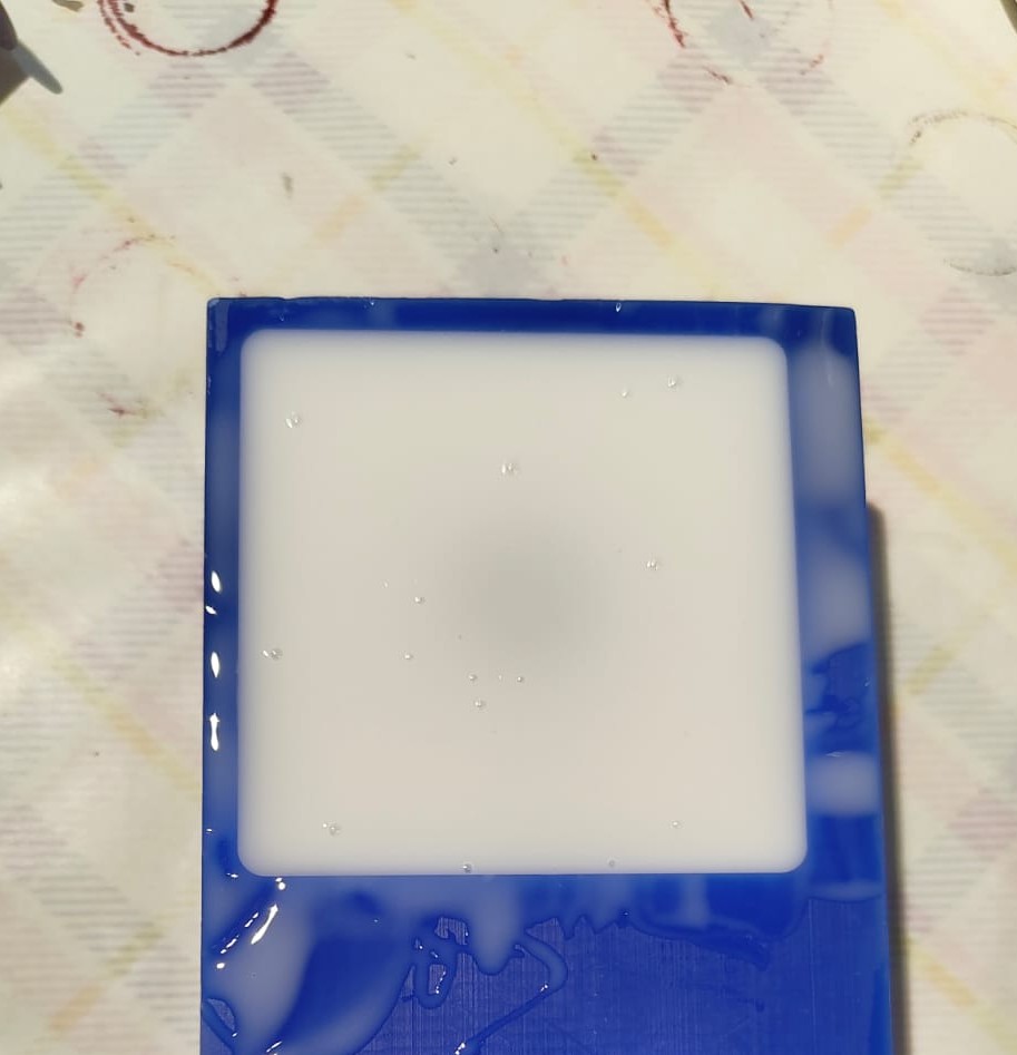
I want 2 silicon mould needed to be made using this mold as I was going to make a sphere. After curing the silicon I removed it and followed all these steps to make the next mould.
Resin Casting
The datasheet for Aditya Ultra Clear Cast Epoxy – 37 is here.
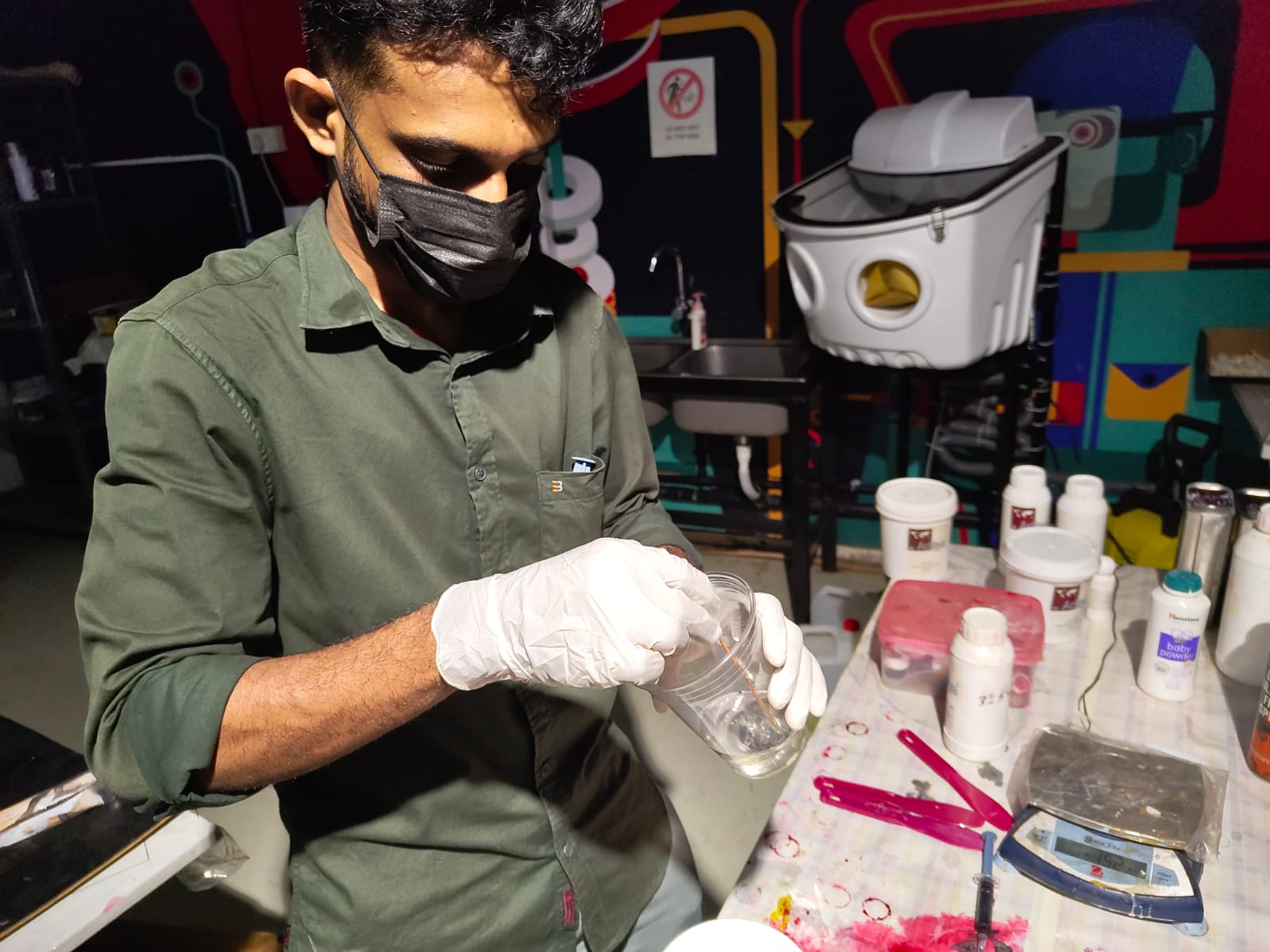
Like the silicon molding I prefered a well ventillated area for resin casting as well. Used latex glove to avoid contact with my body and also used a mask to avoid direct inhaling of the chemicals.
While designing I forgot to add the runner and riser so I done it manually by cytting it with a knife.
They combined both the moulds and apply tape over it to prevent leaking of resin.
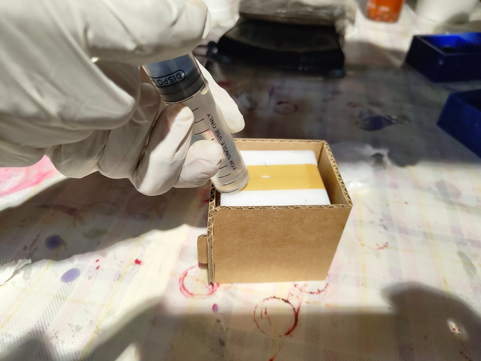
As the sides of the silicon mold was much flexible I made a cardboard enclosure to support the moulds so that it wont flex outside while pouring resin. Took glass and syringe from the inventory. The resin I used in the lab was by Aditya's Epoxy resin A and B. The ratio of A to B was 2:1.
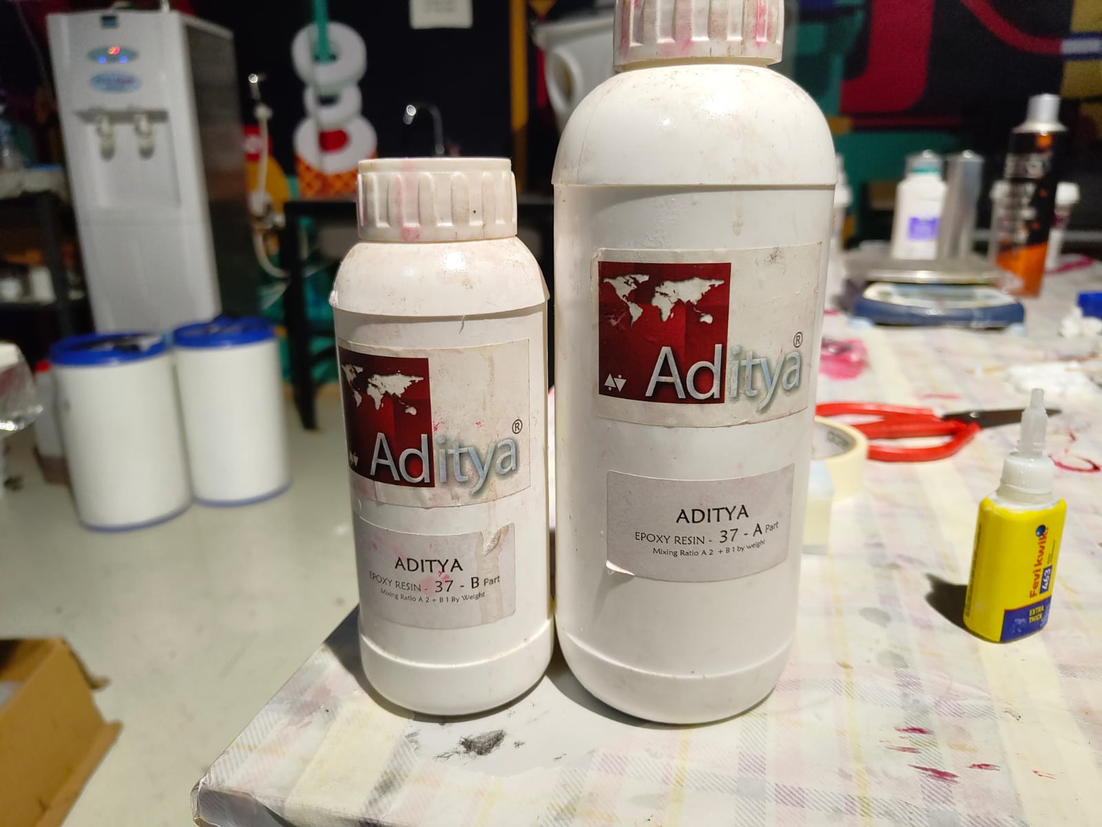
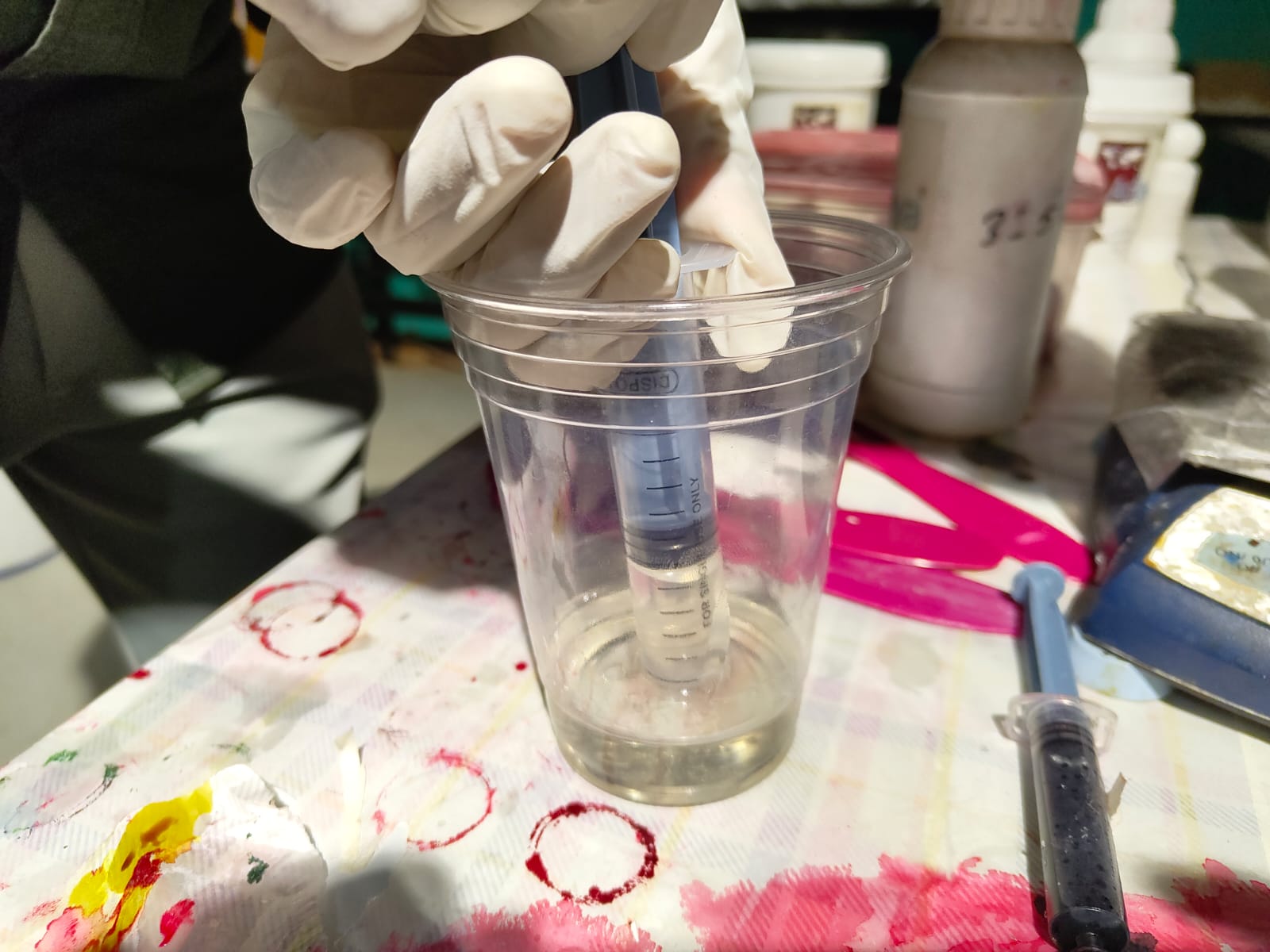
The sphere was 50 mm diameter and while calculated the volume and I got as 65.45ml. So I took some more and make it as 70ml and add 2/3 of A and 1/3 of B and mixed it well and placed it in the vacuum chamber to remove the air bubbbles. Keeping the resin in Vacuum chamber will decreases its curing time also. Then using the syringe I poured the resin on to the silicon resin. Unfortunately the amount of resin was not enough to fill the mould and I needed to mix the resin again.
 |
 |
 |
 |
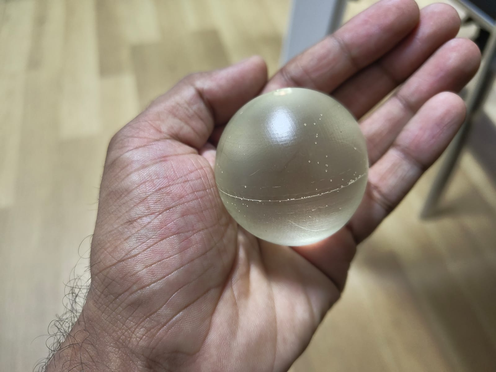
After 5 hours I opened the silicon mold and the sphere was got perfectly. I intended to make it as a clear one but kept in the vacuum chamber slightly changes its color.
 |
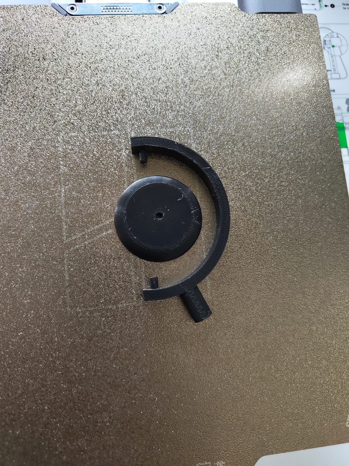
The frame I 3D printed and I assembled the model and the output is shown below.
 |
 |
Conclusion
This week, I explored various types of casting resins and studied different moulding and casting techniques. I then learned how to design a mould, followed by generating the CAM file and milling it using a milling machine. Using the milled mould, I created a silicone mould and finally 3D printed a frame to produce the final desired output.