Input Devices
Objectives for Week 9
- Design a microcontroller board, integrate a sensor, and program it to read and display sensor data.
- Probe an input device's analog levels and digital signals.
Individual Assignment
Group Assignment:
Group Assignment
As part of the group assignment, we tested the INMP441 MEMS microphone and the PS2 Joystick Module Breakout Sensor using an oscilloscope and successfully observed the output.
Group assignment link.
Individual Assignment
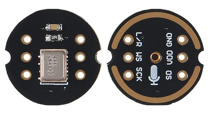
For this week's assignment, I chose the INMP441 MEMS High Precision Omnidirectional Microphone Module as my input device. For my project, I tried to add a microphone to it so that it can be used as a talk-back toy as well.
The INMP441 mems sensor is a high-performance, low-power digital I2S output omnidirectional MEMS microphone. Built on a compact footprint, this module is specifically designed for advanced audio and voice recognition applications. With its inherent low-noise and high Signal-to-Noise Ratio (SNR) attributes, it offers crystal-clear audio capture even in challenging environments. Its compatibility with the I2S interface, a standard used for transmitting digital audio between devices, ensures that it can be integrated into a diverse range of audio processing setups. The INMP441 microphone module is an invaluable component for developers looking to incorporate superior audio input capabilities into their projects.
Block diagram of INMP441
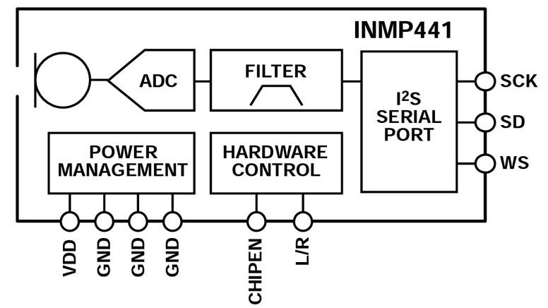
- Microphone- Captures sound waves and converts them into an electrical signal.
- Analog-to-Digital Converter (ADC)- Converts analog signals into digital data.
- Filter- A built-in digital filter is used to process the audio signal and remove unwanted noise.
- I²S Serial Port- This is the main output interface that transmits digital audio data using the I²S protocol.
- Power Management- Regulates power for the internal components.
- Hardware Control- Manages the microphone’s operation, including enabling/disabling functions.
Specifications
- Digital I²S Interface with High-Precision 24-Bit Data
- High SNR of 61 dBA
- High Sensitivity of -26 dBFS
- Flat Frequency Response from 60 Hz to 15 kHz
- Low Current Consumption of 1.4 mA
- Small 4.72 × 3.76 × 1 mm Surface-Mount Package
I2C (Inter- IC Sound) Protocol
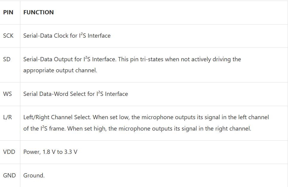
I²S is a serial communication protocol designed for transmitting digital audio data. It uses three main lines: WS (Word Select) for channel selection, SCK (Serial Clock) for synchronization, and SD (Serial Data) for audio transmission. This protocol is widely used in digital audio devices like microphones, DACs, and audio processors for high-quality sound transmission.
I2S works by sending digital audio from one device to another using three wires: a clock line to keep timing, a word select line to choose between left and right audio, and a data line to send the sound bits. One device controls the timing, and the others follow it. The audio data is sent one bit at a time, starting with the most important bit. The receiver reads the data at the right time using the clock. This way, I2S allows smooth and clear audio communication between devices.
Click here to know more about I2S.
ChatGPT promt: Explain I2C protocol.
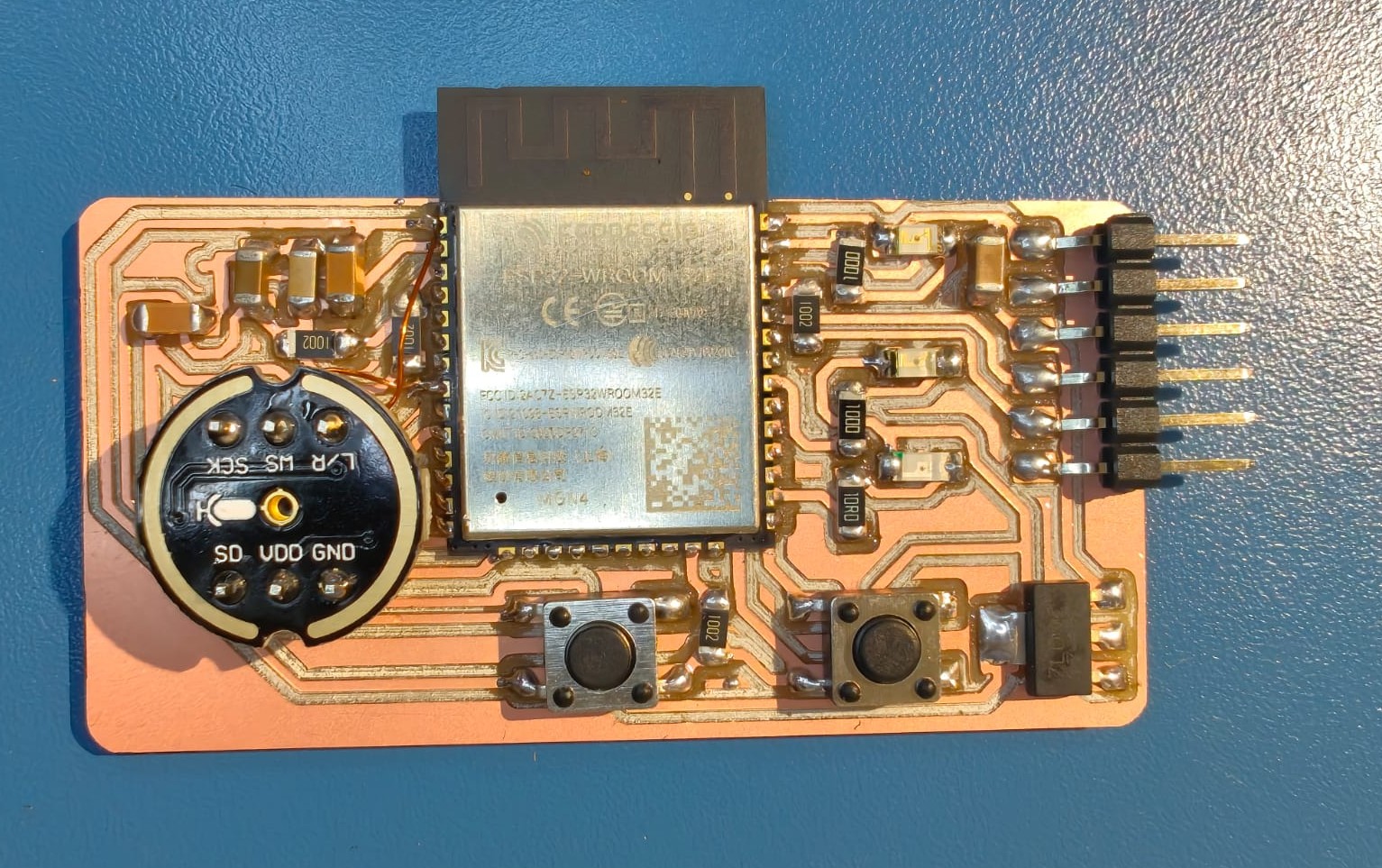
I designed a board with ESP32 microcontroller and INMP441 MEMS microphone. I included 3 LEDs into my board so that I can control the LEDs using the audio input.
Esp32
The ESP32 is a powerful microcontroller with built-in Wi-Fi and Bluetooth, making it ideal for IoT and smart devices. It has a dual-core processor, multiple GPIOs, supports ADC, DAC, I2C, SPI, and UART, and offers low-power modes for battery-powered applications. You can program it using Arduino IDE, MicroPython, or ESP-IDF, and it’s widely used in automation, robotics, and wireless communication projects. Click here for datasheet.
Pin out diagram for ESP32 is given below.

Schematics and PCB layout of my board is given below,
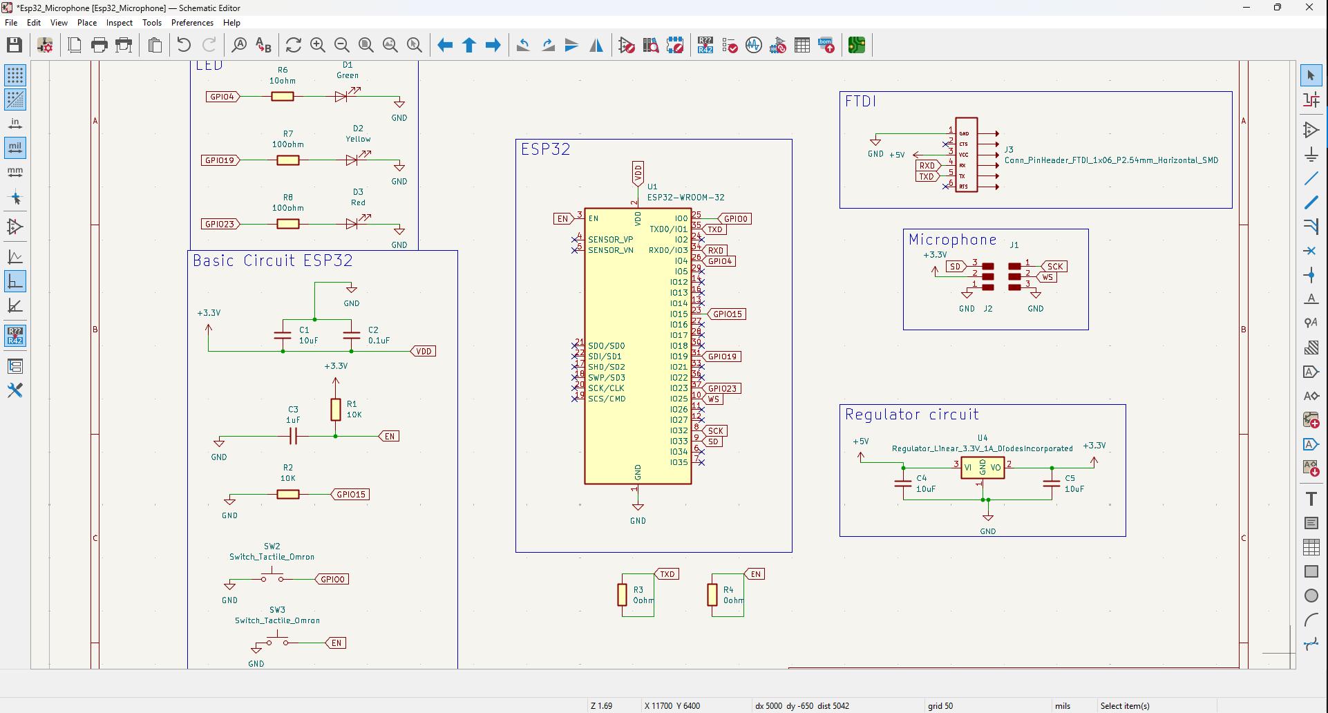
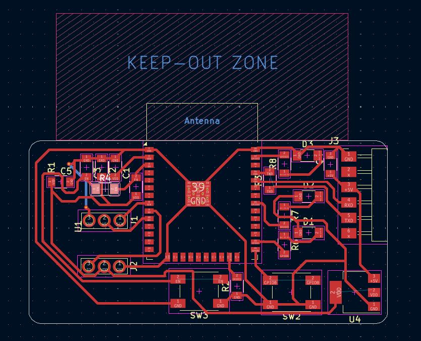
As the foot print for the INMP441 MEMS microphone wasn't available in the footprint library I used 1x03 through hole header pin's footprint for INMP441. While measured I found that the spacing between the pins were 4 header pins.

|

|
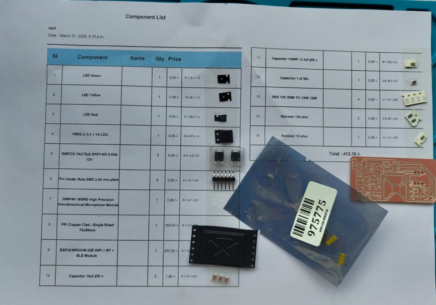
I milled the board and the traces were obtained clearly. I took the components from the inventory and pasted it on the component list.
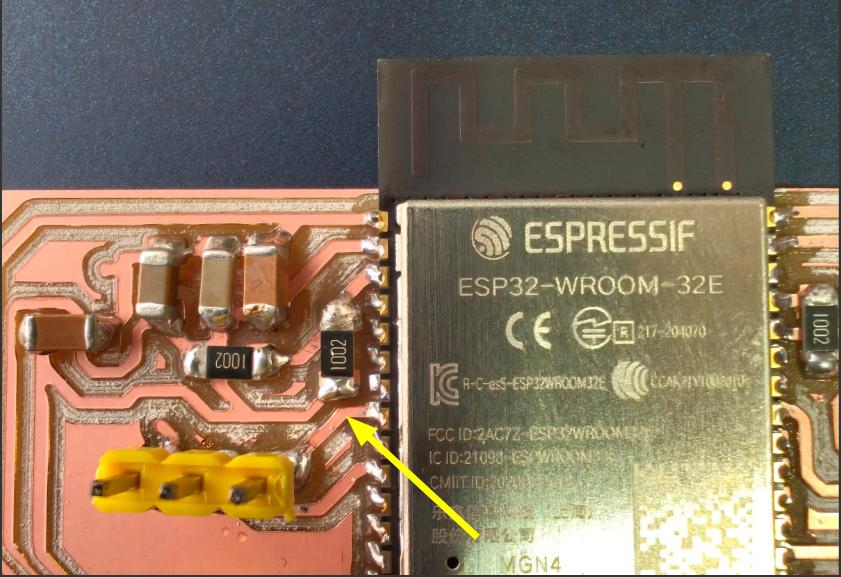
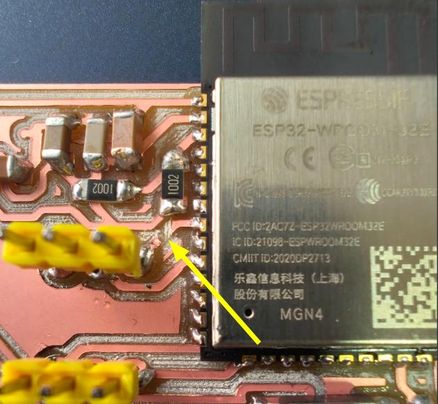
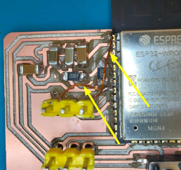
While soldering I found that the holes for the INMP441 were not flipped. I consulted our instructor Saheen and he told me to cut the traces and solder wires accordingly.
 |
 |
 |
 |
Programming
Programmer- FTDI Converter
An FTDI converter is a small device used to connect a computer's USB port to microcontrollers that use serial communication. It helps upload code and send data between the computer and boards like Arduino Pro Mini, ESP8266, or ATtiny, which don’t have a built-in USB port. The converter changes USB signals to serial signals (TX and RX) so the board can understand them. It's commonly used for programming or debugging.
Click here for the programmer details.
I connected my board to my PC using the programmer. Used arduino IDE for programming. I used ChatGPT for generating some codes and used it for testing.
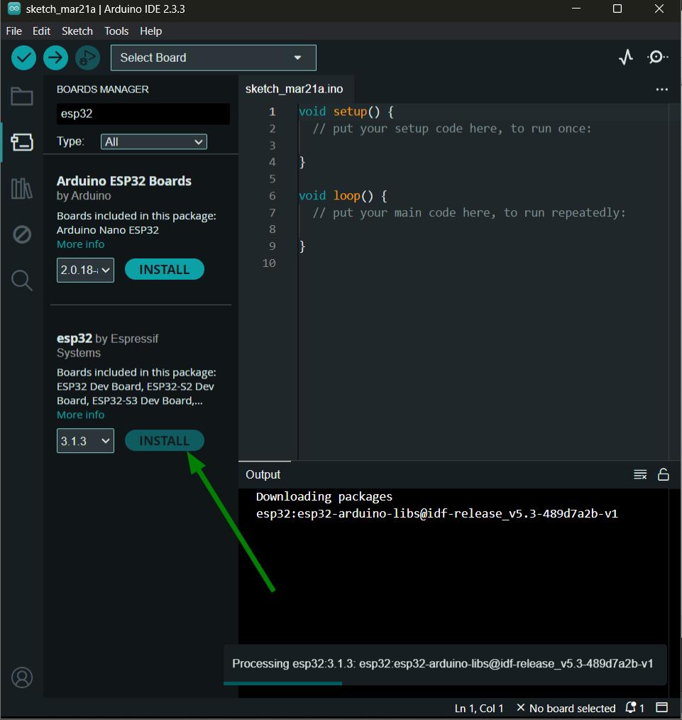
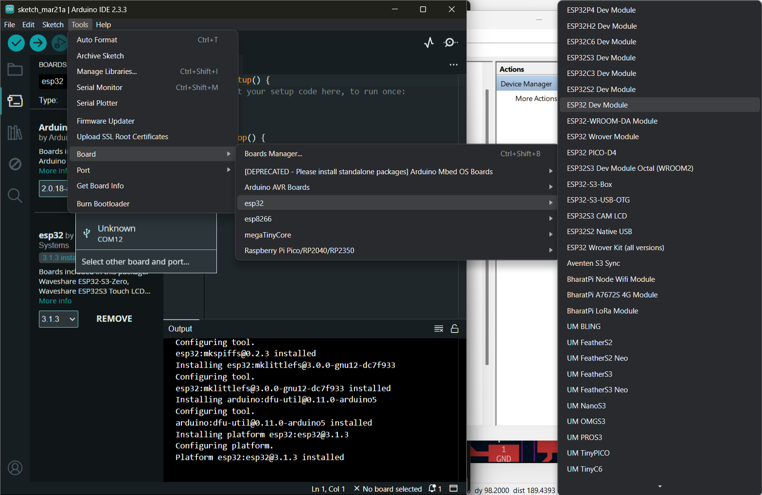
Initially I installed esp32 from board manager and selected the ESP32 Dev Module for programming.
 |
 |
For testing, I tried the basic blink code from the arduino IDE and it works perfectly fine.
Then I tried to make a program for taking input from the INMP441 and display it on the serial plotter. It also works perfectly. I used ChatGPT for genating the program.
  #include <Arduino.h>
    #include <driver/i2s.h>

    // I2S PIN configuration for INMP441
    #define I2S_WS  25  // Word Select (LRCLK)
    #define I2S_SCK 32  // Serial Clock (BCLK)
    #define I2S_SD  33  // Serial Data (DOUT)

    // I2S Configuration
    void i2s_setup() {
        i2s_config_t i2s_config = {
            .mode = (i2s_mode_t)(I2S_MODE_MASTER | I2S_MODE_RX),
            .sample_rate = 16000,
            .bits_per_sample = I2S_BITS_PER_SAMPLE_32BIT,
            .channel_format = I2S_CHANNEL_FMT_ONLY_LEFT,
            .communication_format = I2S_COMM_FORMAT_I2S_MSB,
            .intr_alloc_flags = ESP_INTR_FLAG_LEVEL1,
            .dma_buf_count = 8,
            .dma_buf_len = 1024,
            .use_apll = false,
            .tx_desc_auto_clear = false,
            .fixed_mclk = 0
        };

        // Corrected order of fields
        i2s_pin_config_t pin_config = {
            .bck_io_num = I2S_SCK,
            .ws_io_num = I2S_WS,
            .data_out_num = I2S_PIN_NO_CHANGE,  // Unused
            .data_in_num = I2S_SD
        };

        // Install and start I2S driver
        i2s_driver_install(I2S_NUM_0, &i2s_config, 0, NULL);
        i2s_set_pin(I2S_NUM_0, &pin_config);
    }

    void setup() {
        Serial.begin(115200);
        i2s_setup();
        Serial.println("INMP441 Microphone Test Started...");
    }

    void loop() {
        int32_t sampleBuffer[1024]; // Buffer for audio samples
        size_t bytesRead;

        // Read from I2S
        i2s_read(I2S_NUM_0, sampleBuffer, sizeof(sampleBuffer), &bytesRead, portMAX_DELAY);

        int numSamples = bytesRead / sizeof(int32_t);
        int32_t sum = 0;

        // Process audio data (calculate average amplitude)
        for (int i = 0; i < numSamples; i++) {
            sum += abs(sampleBuffer[i] >> 14);
        }

        int averageAmplitude = sum / numSamples;

        // Serial.print("Amplitude: ");
        Serial.println(averageAmplitude);

        delay(100);
    }
ChatGPT promt: Write a program to read the audio data from the INMP441 microphone and display it on the serial monitor.(Provided the screenshot of the schematics.)
As I included 3 LEDs in my board I tried to make these LEDs as an equlizer by taking the input from the microphone. Used ChatGPT for generating the program.
  #include <Arduino.h>
    #include <driver/i2s.h>

    // I2S PIN configuration for INMP441
    #define I2S_WS  25   // Word Select (LRCLK)
    #define I2S_SCK 32   // Serial Clock (BCLK)
    #define I2S_SD  33   // Serial Data (DOUT)

    // LED Pins
    #define LED_GREEN  4   // Low amplitude
    #define LED_YELLOW 19  // Medium amplitude
    #define LED_RED    23  // High amplitude

    // I2S Configuration
    void i2s_setup() {
        i2s_config_t i2s_config = {
            .mode = (i2s_mode_t)(I2S_MODE_MASTER | I2S_MODE_RX),
            .sample_rate = 16000,
            .bits_per_sample = I2S_BITS_PER_SAMPLE_32BIT,
            .channel_format = I2S_CHANNEL_FMT_ONLY_LEFT,
            .communication_format = I2S_COMM_FORMAT_I2S_MSB,
            .intr_alloc_flags = ESP_INTR_FLAG_LEVEL1,
            .dma_buf_count = 8,
            .dma_buf_len = 1024,
            .use_apll = false,
            .tx_desc_auto_clear = false,
            .fixed_mclk = 0
        };

        i2s_pin_config_t pin_config = {
            .bck_io_num = I2S_SCK,
            .ws_io_num = I2S_WS,
            .data_out_num = I2S_PIN_NO_CHANGE, // Unused
            .data_in_num = I2S_SD
        };

        i2s_driver_install(I2S_NUM_0, &i2s_config, 0, NULL);
        i2s_set_pin(I2S_NUM_0, &pin_config);
    }

    void setup() {
        Serial.begin(115200);
        i2s_setup();

        pinMode(LED_GREEN, OUTPUT);
        pinMode(LED_YELLOW, OUTPUT);
        pinMode(LED_RED, OUTPUT);

        Serial.println("INMP441 Equalizer Started...");
    }

    void loop() {
        int32_t sampleBuffer[1024]; // Buffer for audio samples
        size_t bytesRead;

        // Read audio samples
        i2s_read(I2S_NUM_0, sampleBuffer, sizeof(sampleBuffer), &bytesRead, portMAX_DELAY);

        int numSamples = bytesRead / sizeof(int32_t);
        int32_t sum = 0;

        // Calculate average amplitude
        for (int i = 0; i < numSamples; i++) {
            sum += abs(sampleBuffer[i] >> 14);
        }

        int avgAmplitude = sum / numSamples;

        Serial.print("Amplitude: ");
        Serial.println(avgAmplitude);

        // LED equalizer logic
        if (avgAmplitude < 500) {
            digitalWrite(LED_GREEN, HIGH);
            digitalWrite(LED_YELLOW, LOW);
            digitalWrite(LED_RED, LOW);
        }
        else if (avgAmplitude >= 500 && avgAmplitude < 2000) {
            digitalWrite(LED_GREEN, HIGH);
            digitalWrite(LED_YELLOW, HIGH);
            digitalWrite(LED_RED, LOW);
        }
        else {
            digitalWrite(LED_GREEN, HIGH);
            digitalWrite(LED_YELLOW, HIGH);
            digitalWrite(LED_RED, HIGH);
        }

        delay(100);
    }
ChatGPT Promt: I have 3 LEDs and an INMP441 in my board. Write a program to make the LEDs as an equaliser. (Provided the screenshot of the schematics.)
Heroshot

Conclusion
This week, I gained valuable insights into various input devices and their applications. I successfully designed and developed a PCB integrating the INMP441 digital microphone with the ESP32 microcontroller. Through hands-on exploration, I deepened my understanding of the INMP441, its working principles, and how to interface it using the I²S protocol.