Computer Controlled Machining.
Objectives for Week 7
- Design, mill, and assemble a large, meter-scale structure.
- Do lab's safety training.
- Test runout, alignment, fixturing, speeds, feeds, materials, and toolpaths for the machine
Individual Assignment
Group Assignment:
Group Assignment
Group assignment link.
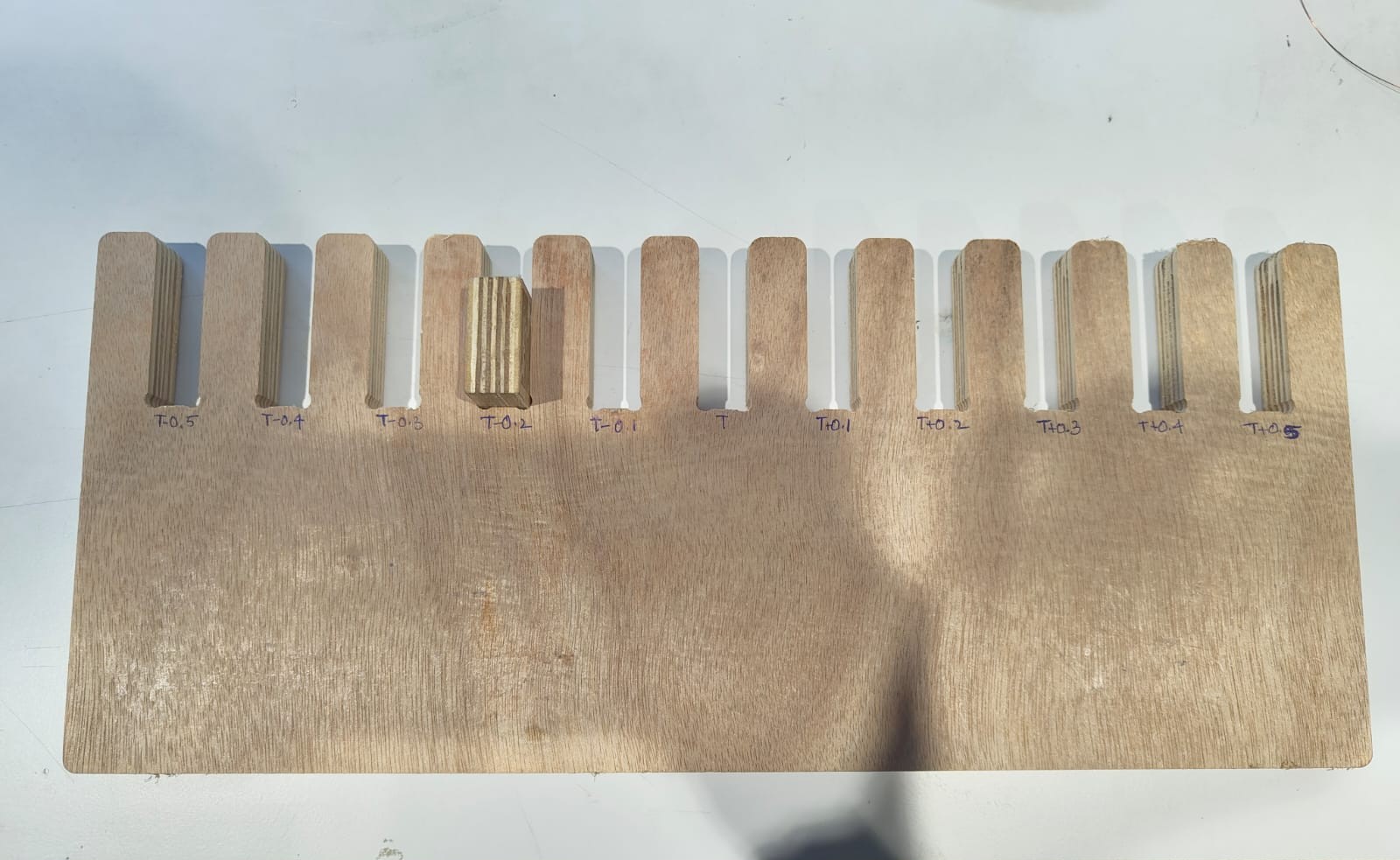
In our group assignment, we learned about the necessary safety equipment and precautions for operating the machine and post-processing. We then designed a jig with varying values to accurately measure the machine's runout. After testing the feed and speed rates, we created CAM toolpaths using VCarve software. Finally, we post-processed the jig and determined the runout value to be thickness - 0.2mm.
Computer-Controlled Machining
Computer-controlled machining is a process where computers guide machines like CNC mills, lathes, and routers to cut, shape, or engrave materials with high precision. It uses digital designs (CAD files) that are converted into machine instructions (G-code) to automate the cutting process. This method ensures accuracy, repeatability, and efficiency, making it ideal for manufacturing complex parts in industries like aerospace, automotive, and prototyping.
ChatGPT Promt: What is Computer-Controled Machining.
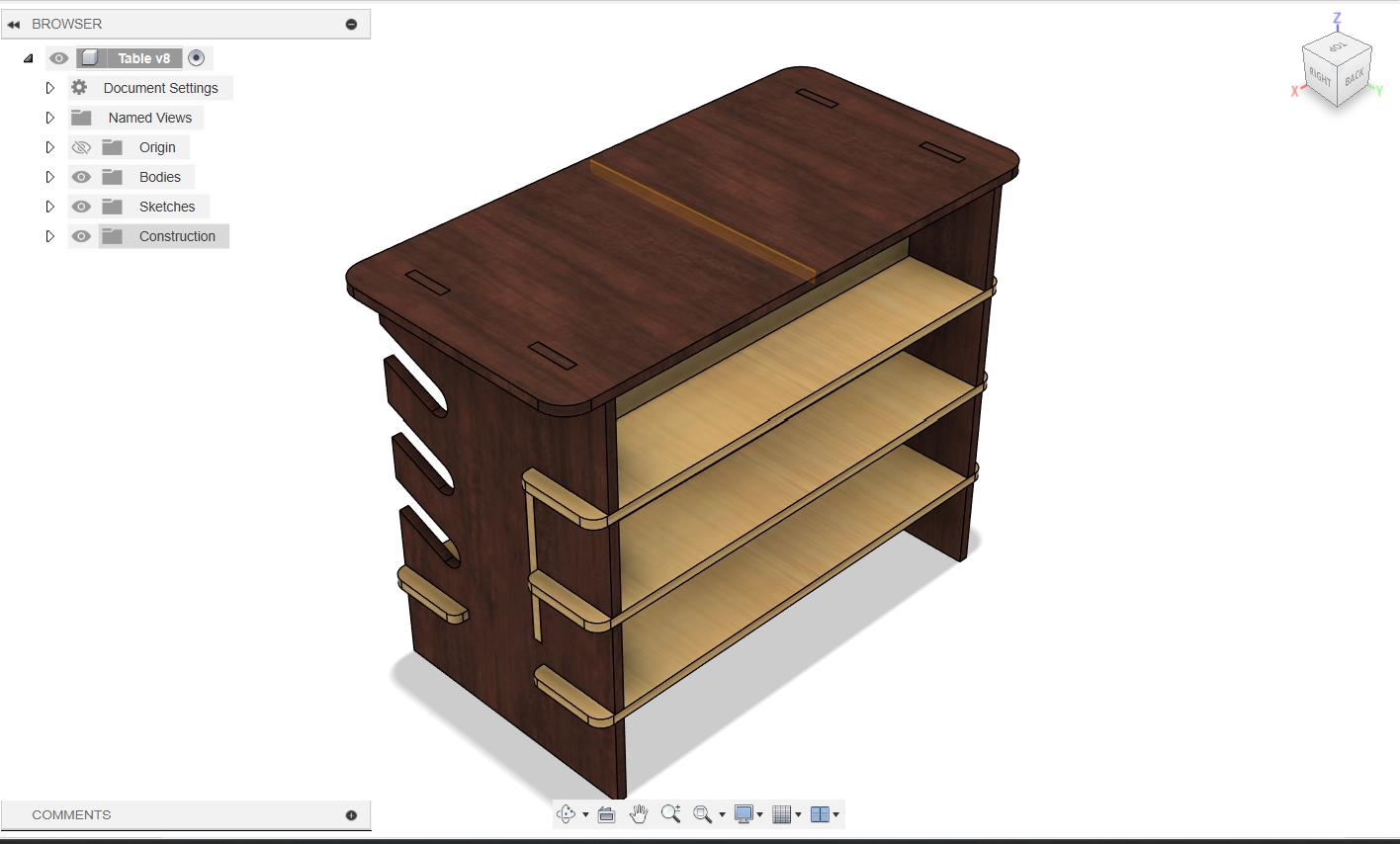
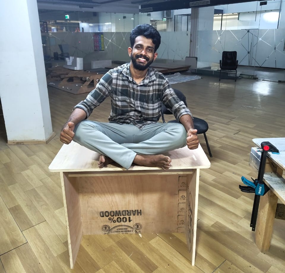
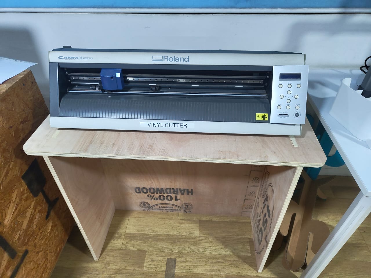
This week individual assignment is to design, mill and assemble something big minimum of one meter square. So I tried to make a simple book shelf for offices, but discussing it with my instructor Saheen he gave me a suggestion to make a table for the Vinyl cutter for our lab which was essential then. So I dropped the bookshelf idea and worked on the table. I designed the table on Fusion 360. With multiple iterations I got the final design which I want to make.
Design
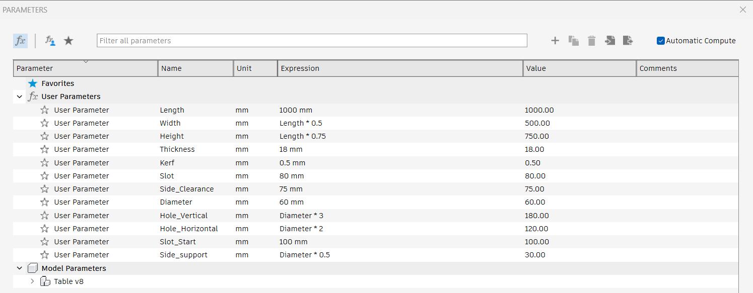
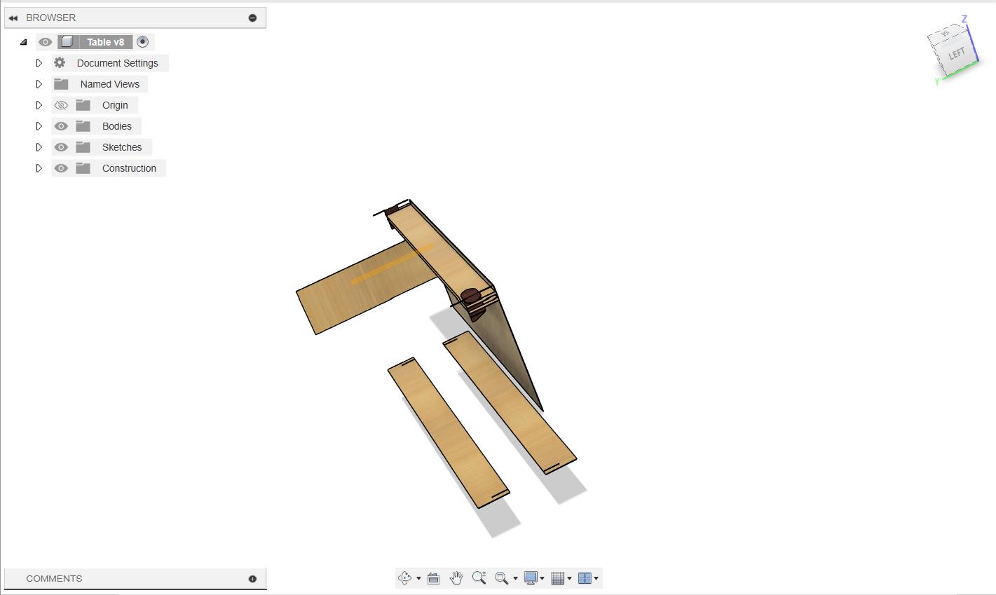
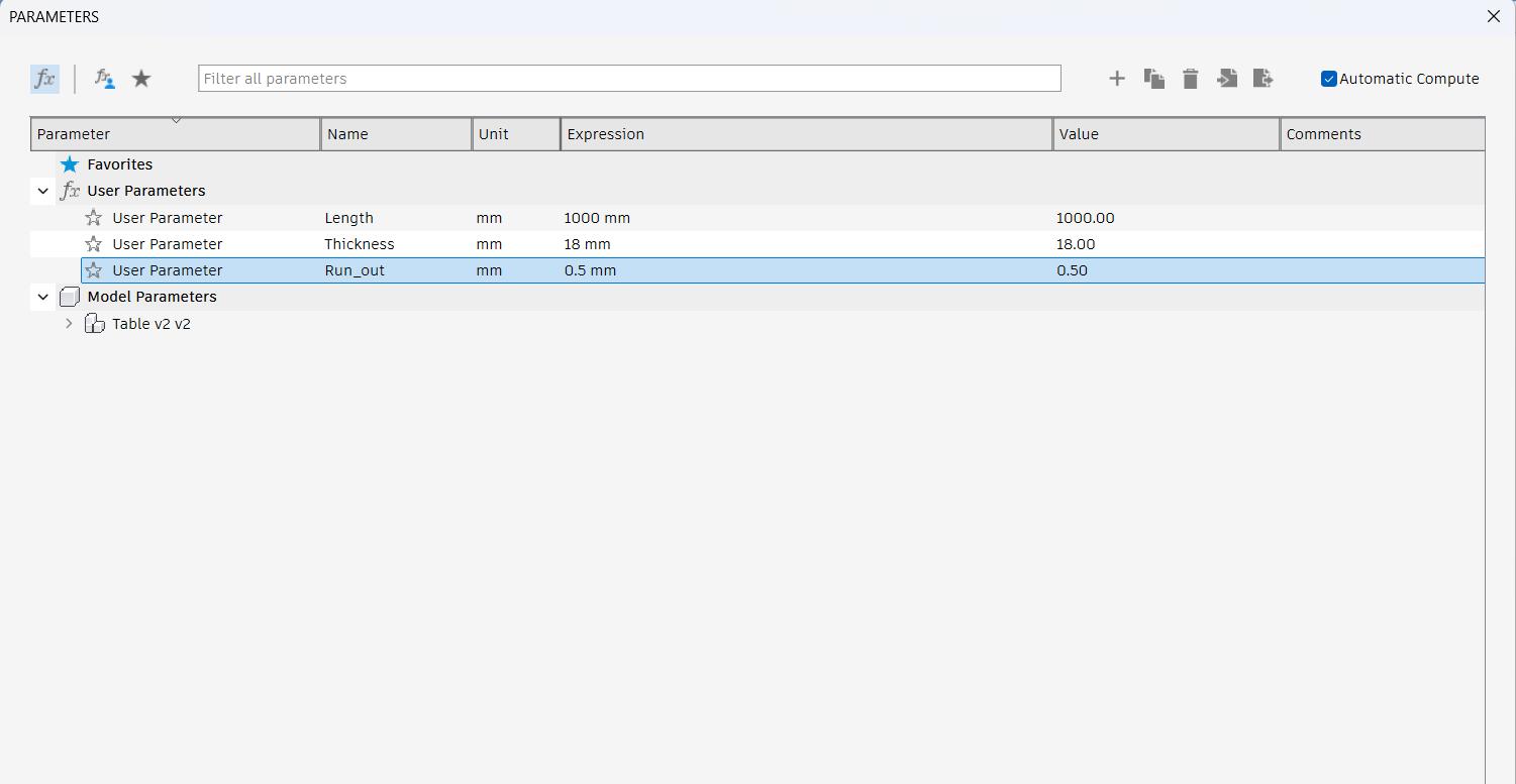
I designed the table on fusion 360. The main challenge was to make the design in parametric. I was a beginner in parametric design. Although I tried it in Computer Controlled Cutting week, I need to make more efforts to make the design as a parametric design. Initially, I designed it with multiple variables and it fails when I change the values of the variables. Then I tried the design with three variables and this time also the design fails when I changed the values. Then I discussed it with my instructor and he gave me some ideas about the parametric design and he told me to design it with two variable. Designing it with two variables I was able to control the design according to different values and this time I got the idea of parametric design.
- Initial Design
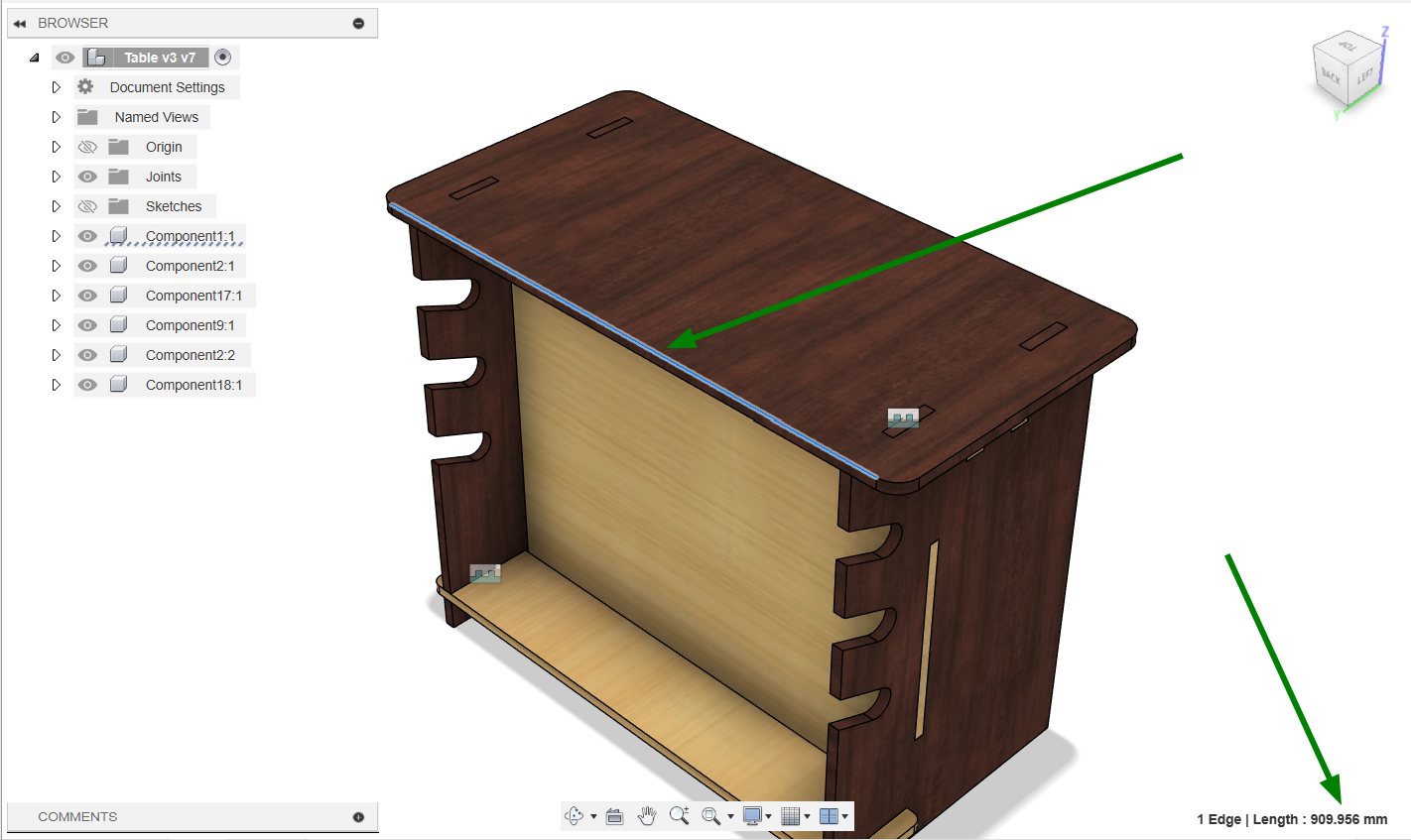
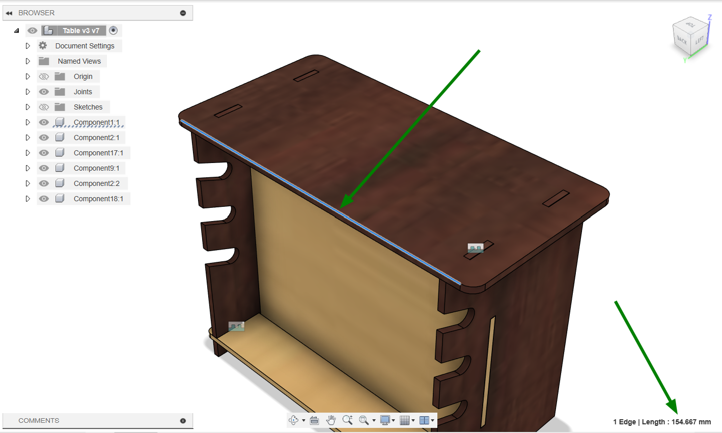
Here I used many variables so that it was very difficult for me to control the parameters and whenever I tried to control the parameters the design got fails continuously.
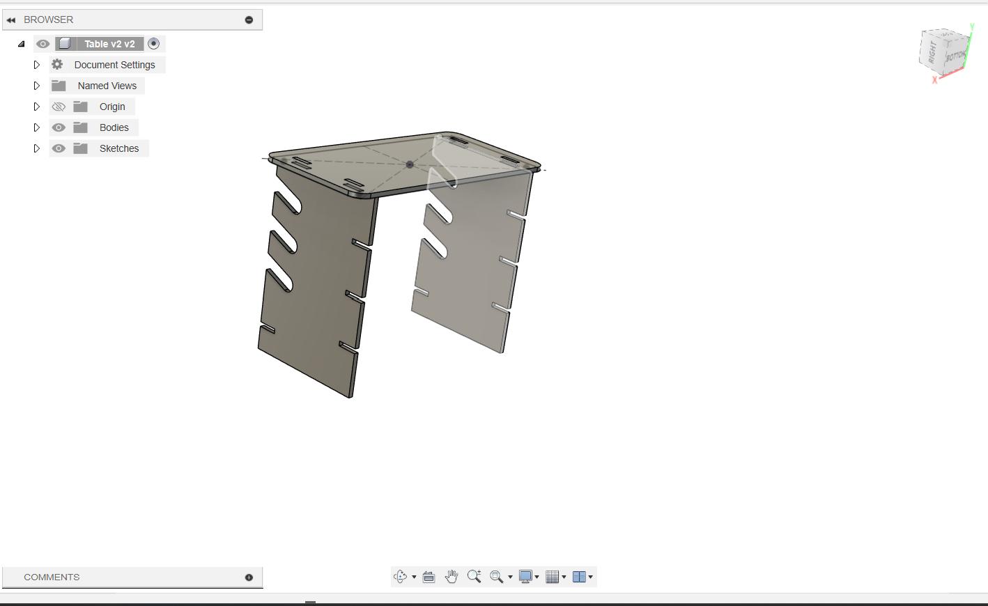
- Second Design
I tried to control the design with three different variables and this time also I can't able to control the design and it was become too complicated for me to control the design.
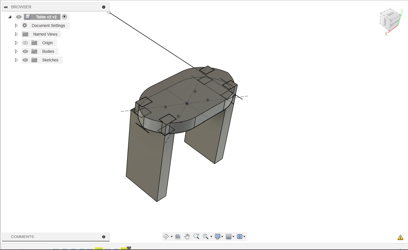
- Third and Final Design
This time I tried to control the design with two variables, thickness and runout. Hopefully this time the design was worked as expected and I was able to control the design by changing the parameters.
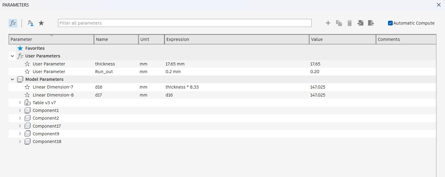 |
|
Testing
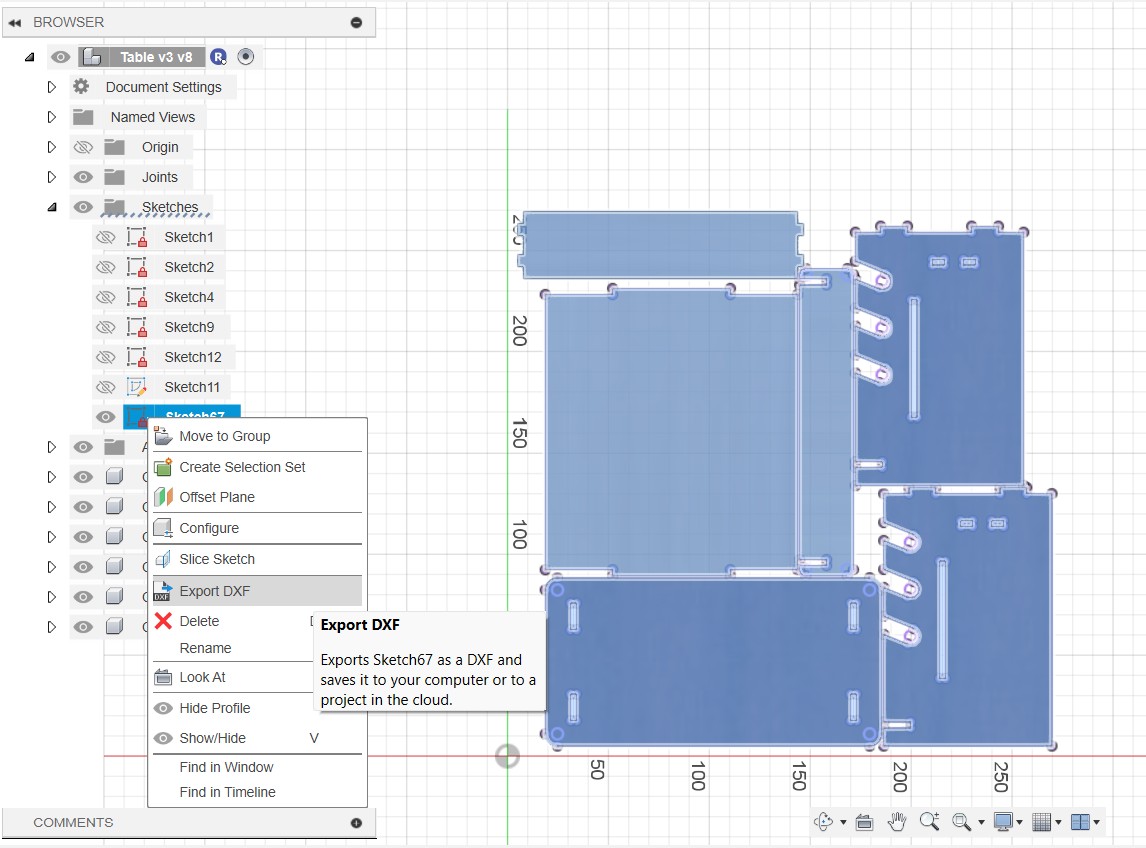
Before creating the actual model, it is essential to create a miniature model of the design to verify all the design and fitment were correct. As the model was design parametric, I changed the thicknes value to 3mm runout value to 0.1mm so that I can cut the design in 3mm thick card board in our Laser cutter. After changing these values I arranged the file using the arrange tool in fusion 360. Projected the faces and exported it as .dxf format so that it can be machined in the laser cutter.
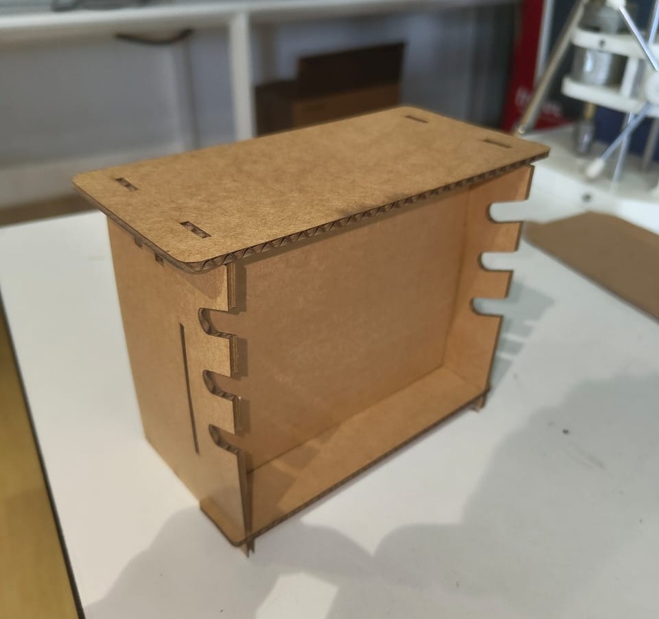
After making the miniature model it was clear that the fitments and the values were correct so I can make the actual model.
Dogbone
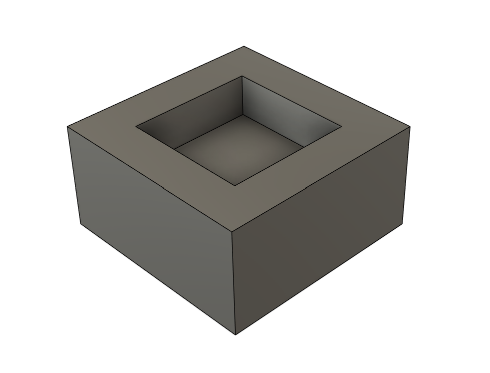
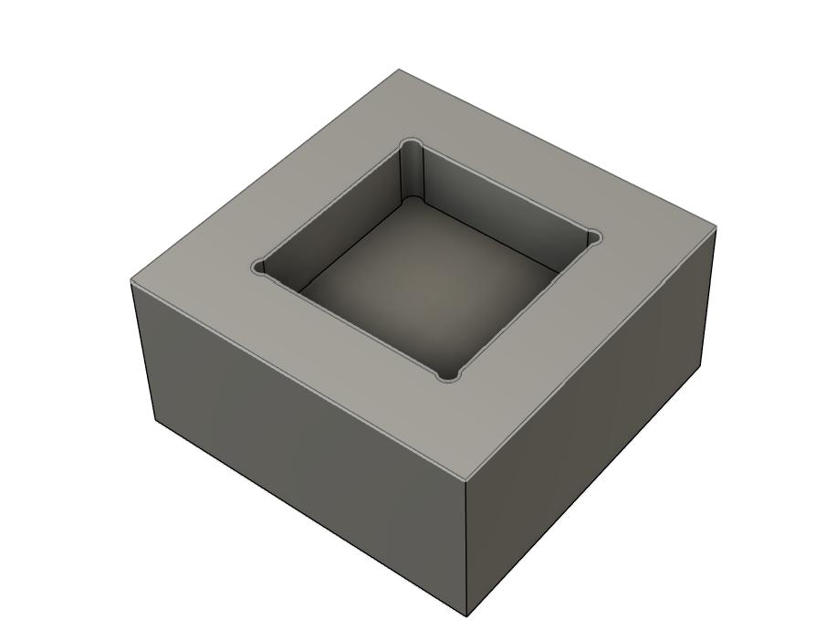
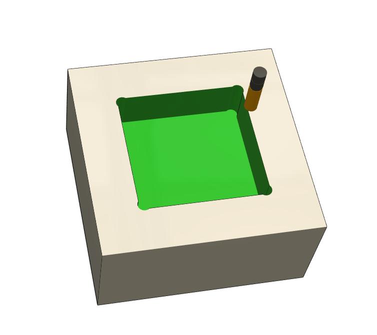
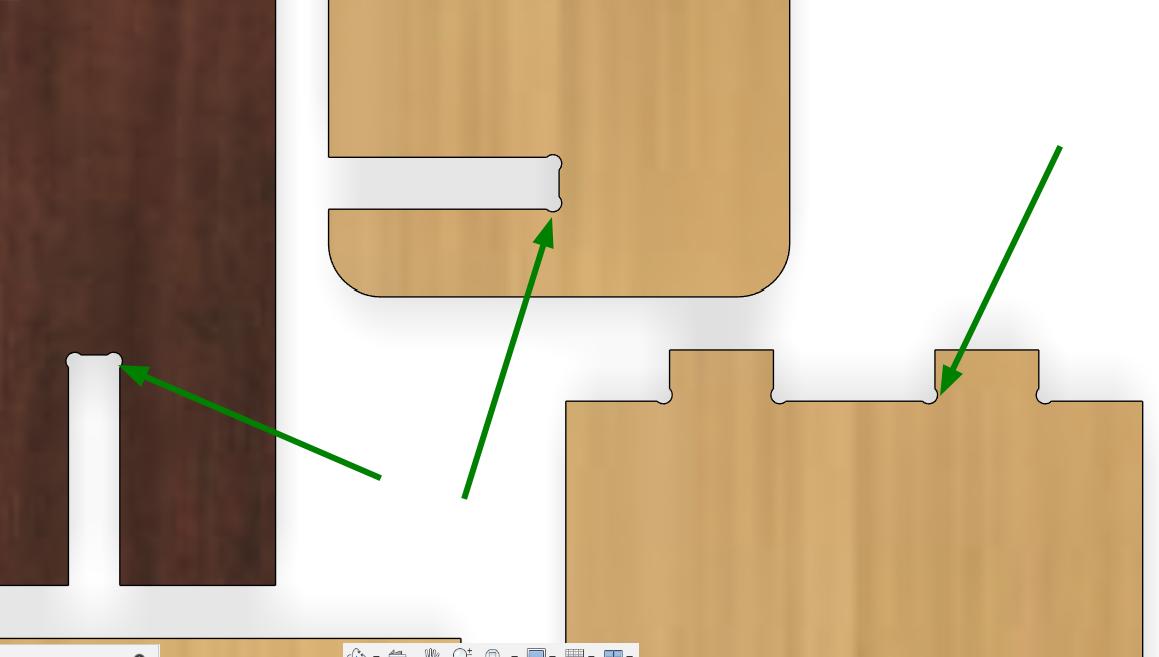
When routing, we cannot achieve perfectly sharp inside corners because the cutting tool always leaves a radius equal to its own. This curve cannot be completely eliminated, only minimized by using smaller diameter end mills. To ensure proper fitting and joining, we add dogbones, which allow the cutter to remove extra material in the corners. However, even with dogbones, the result will not be exactly as designed; they simply help make the fitment more accurate.
Click here to get the dogbone extension for Fusion 360.
 |
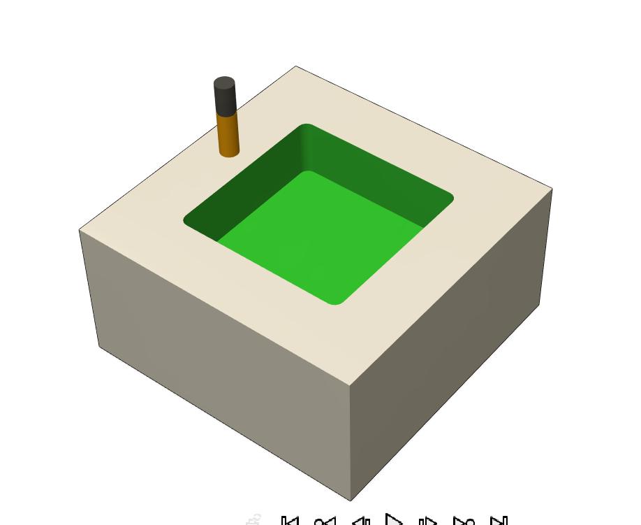 |
So adding the dogbone can eliminate the radius inside.
 |
 |
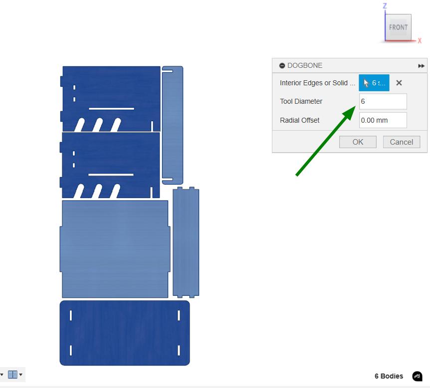
I am going to make this design in an 18mm plywood. The plywood not always 18mm and it always have some dimensional variations. So I measured the thickness of the plywood multiple places and take the average of the values. The value I got was 17.7mm. So I changed the thickness to 17.7mm in the design as well. Arranged the design and created the dogbone. The dogbone extension was added to Fusion 360 by following the above link.
As I was going to use 6mm endmill I given tool diameter as 6mm in the dogbone. So that it will automatically calculate the dogbone needed for 6mm tool and creates dogbone in the selected areas.
 |
 |
Inorder to CAM the design in Vcarve software, the file needed to be converted into a 2D file. So I projected the faces and exported the sketch as .dxf.
V Carve
VCarve is a software used with ShopBot CNC machines to design and generate toolpaths for cutting, carving, and engraving. It supports 2D and 2.5D operations like profiling, pocketing, and V-carving, making it ideal for sign-making and detailed woodworking. VCarve creates SBP toolpaths that ShopBot can read, allowing users to preview cuts before running them on the machine.
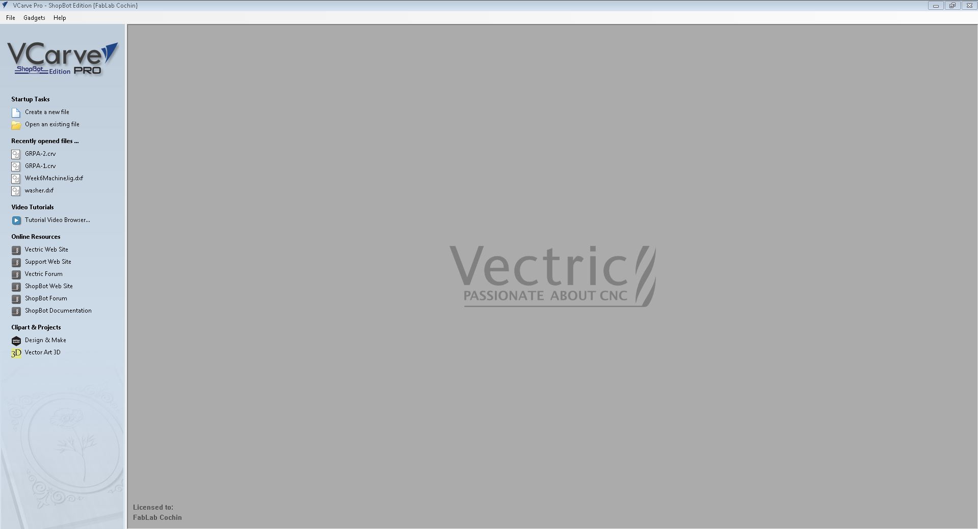
The CAM steps are as follows,
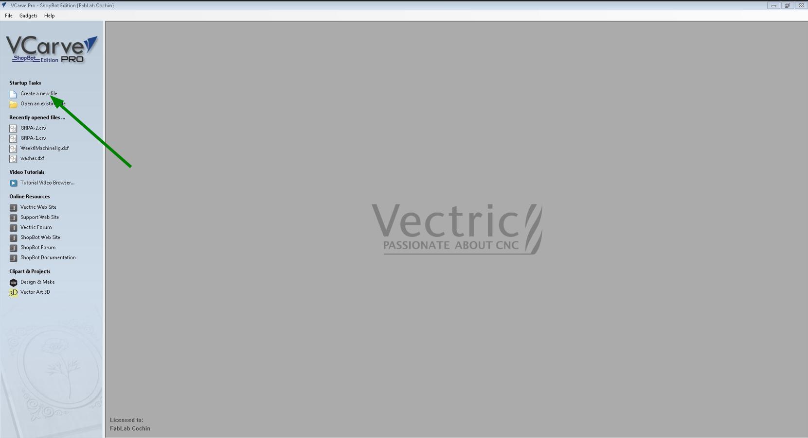
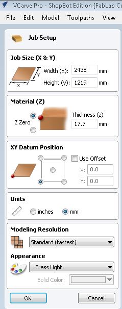
- Initially using 'Create a new file' to create a new file and set the stock size(X,Y,and Z) of the workpiece and set the unit to mm.
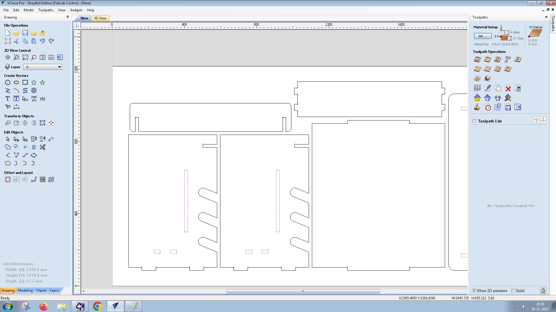
- File → Import → Import Vectors to import the .dxf file.
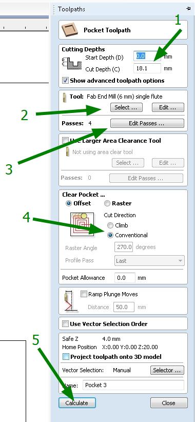
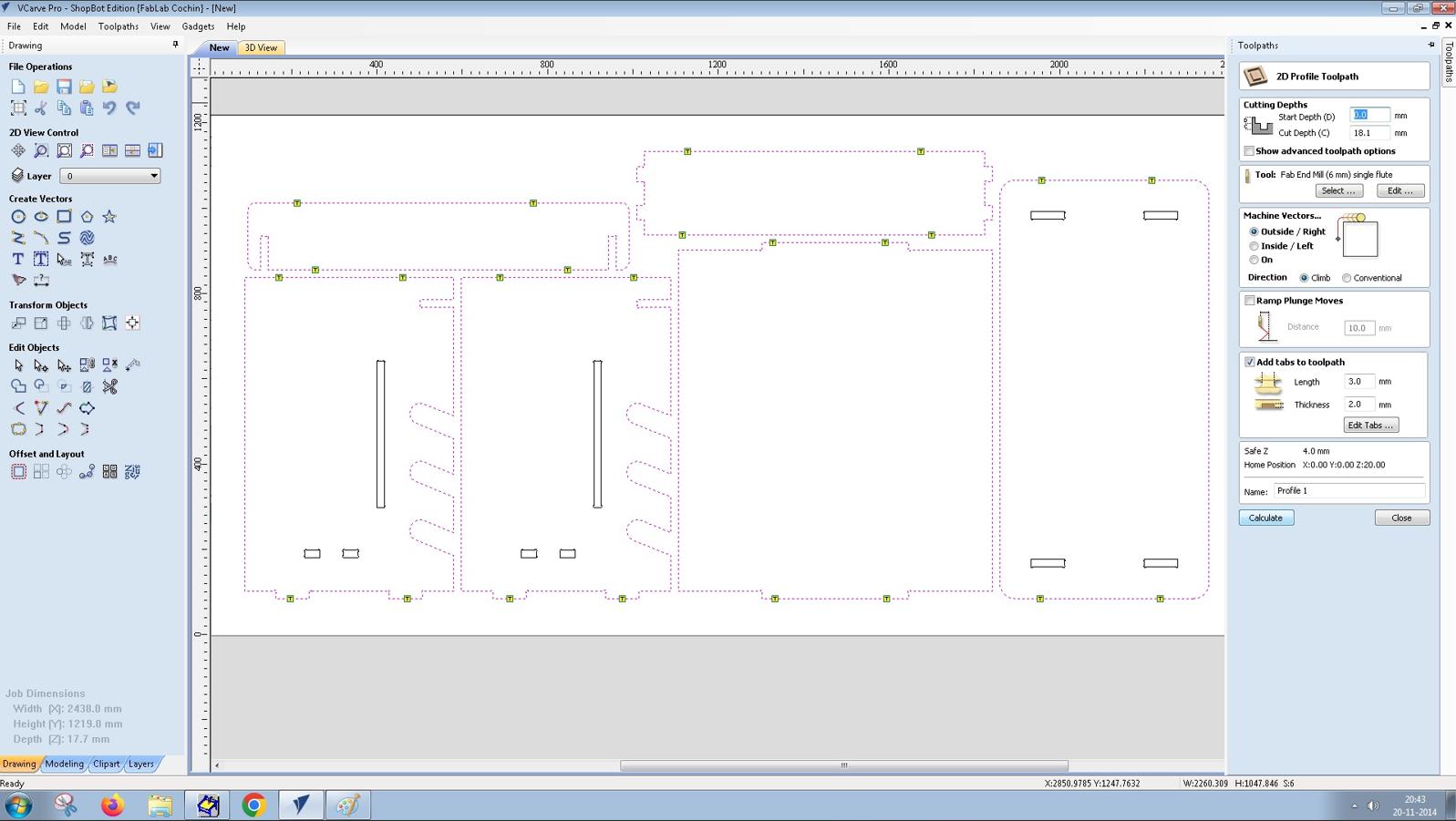
- Select all the inside features and choose the Pocket Toolpath. In pocket toolpath specify 1.Cutting depths, 2. Tool, 3. Passes, 4. Cut direction and click 5. Calculate to generate the tool path.
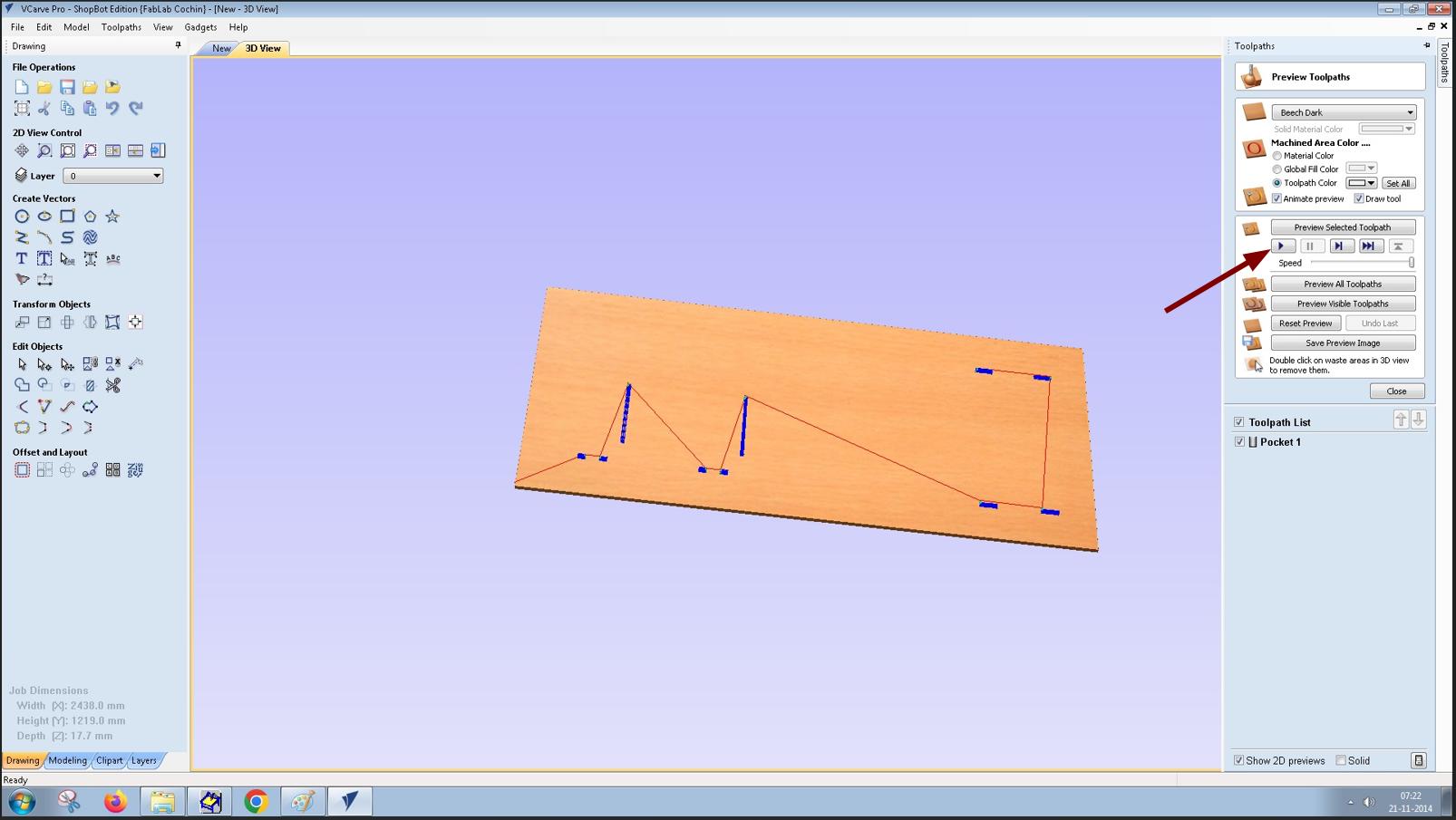
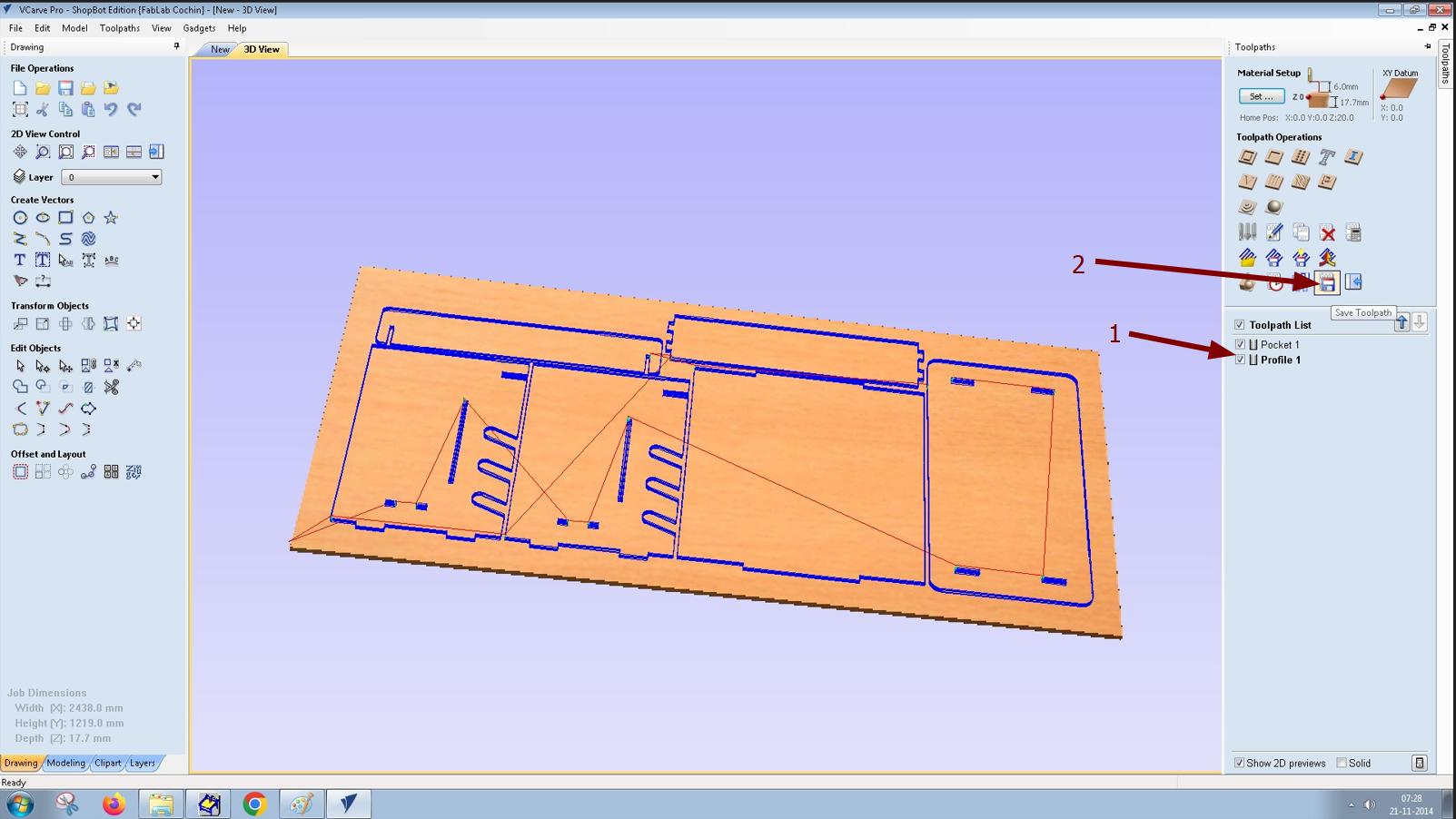
- In 3D View simulate the toolpath to check whether it is correct.
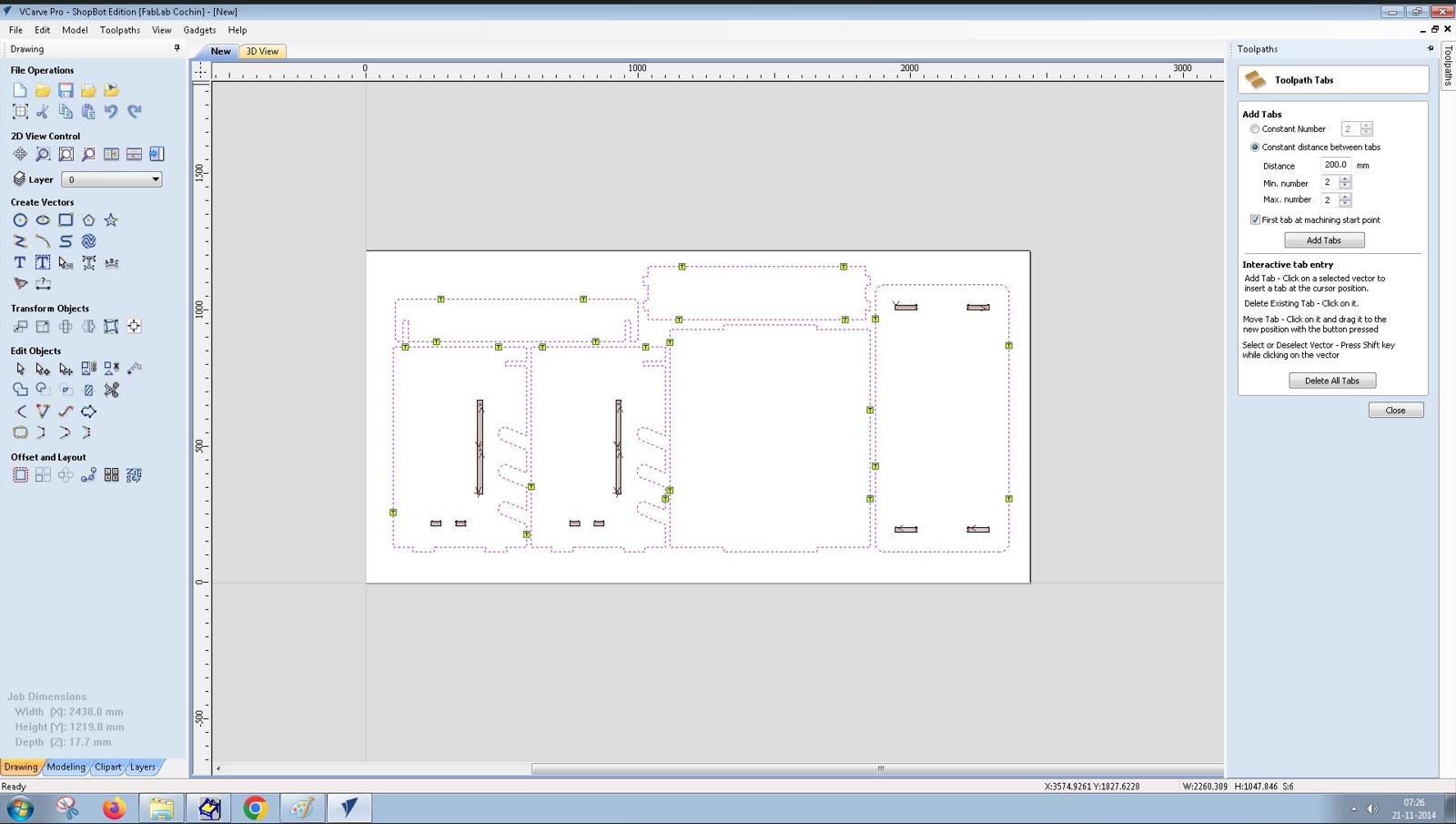
- Select the outer profiles and choose 2D Profile Toolpath. Specify Cut depths, Tool, Compensation left or right and Create tabs. Click calculate to generate the tool path.
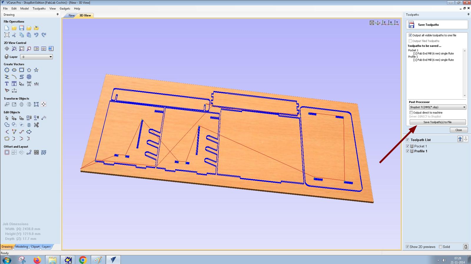
- Selected all the toolpaths and saved it. The toolpaths are converted into G Codes and saved as .spb file.
 |
 |

 |
 |
 |
 |
 |
 |
Clamping the workpiece
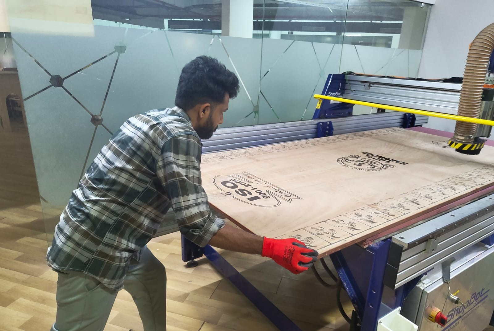
- With the help of one of our instructor Sibin, I loaded the workpiece on to the machine's bed.
- While arranging in Fusion 360 I given a 20mm frame width to clamp the workpiece.
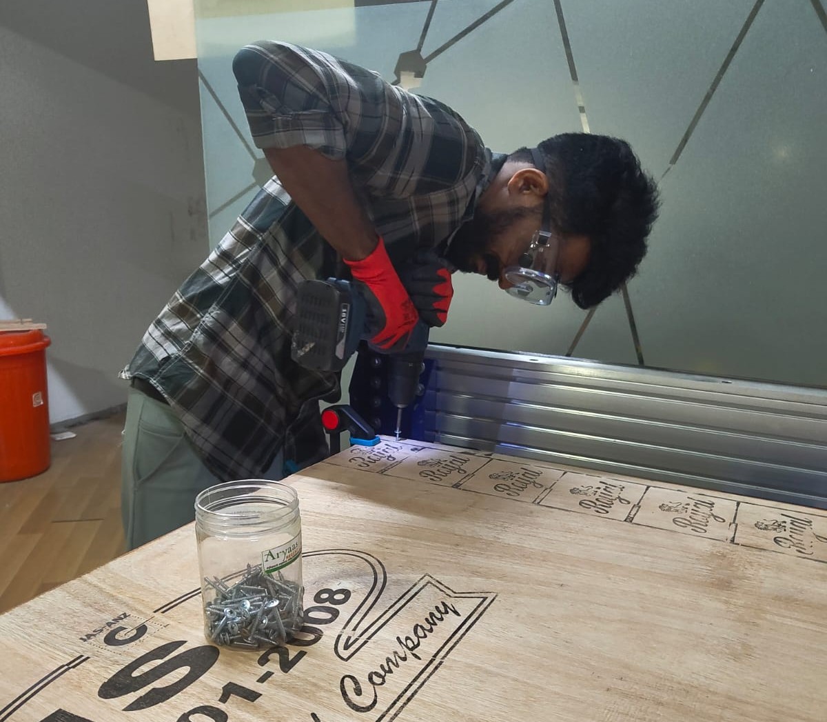
- I clamped the workpiece with the help of screws and make sure that the tool will not collide with the screws.
- Moved the tool to one end of the machine and I took the X and Y offset. With the help of touch plate I took the Z offset as well.
Running the toolpath
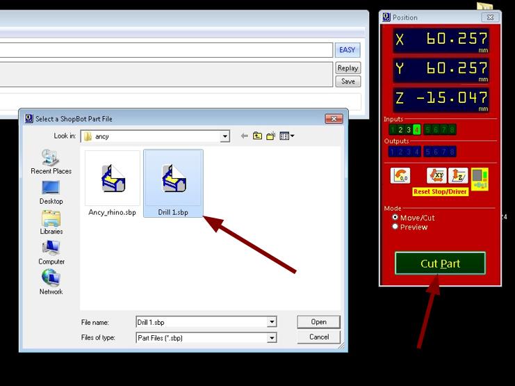
- Loaded the program to the machine's software by using the Cut Part option.
- Clicked Start and a dialogue box appears saying that turn ON the spindle and click OK. Spindle is turned ON by using the Spindle start switch and wait for a few seconds to stable the RPM.
- Clicked Ok and the machine starts routing the workpiece according to the design provided.
Post Processing
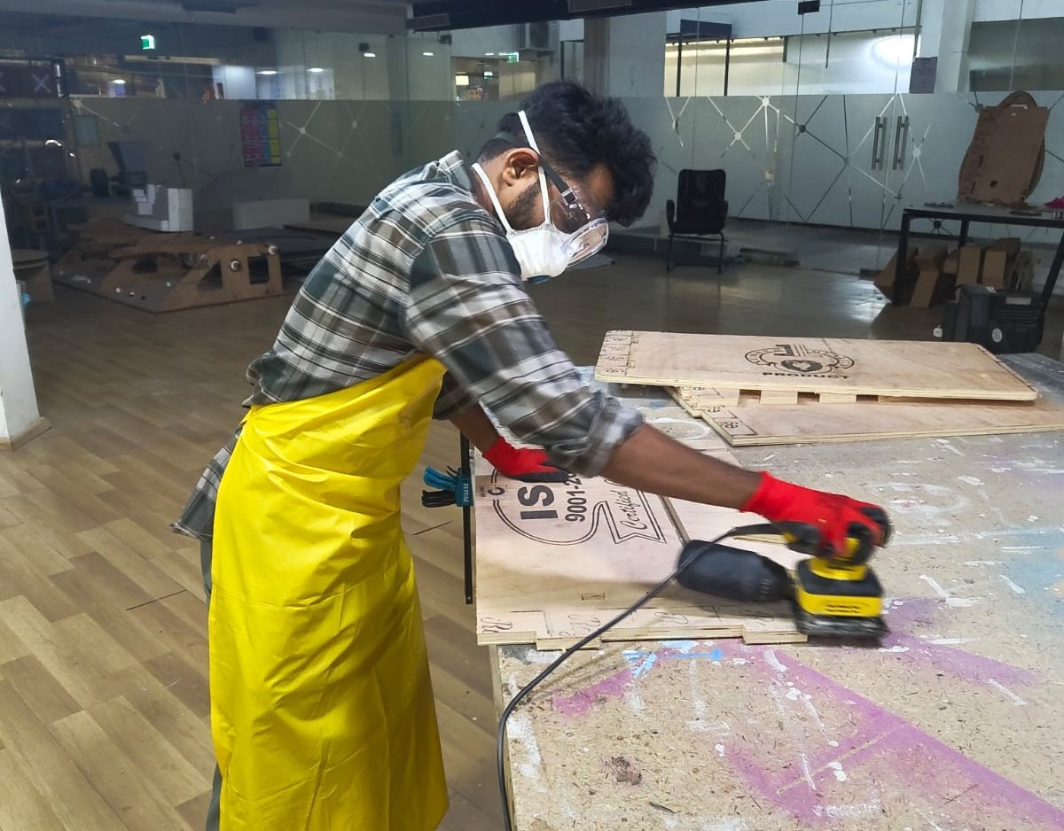
With the help of chisel the tabs were removed. Using the reciprocating sander the pieces were sanded and finished. The burrs in the edges of the joining parts were finished using a file.
Assembly
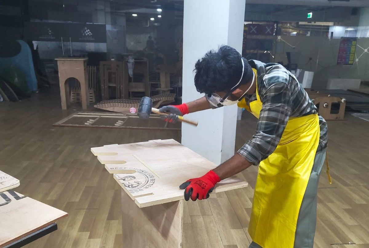
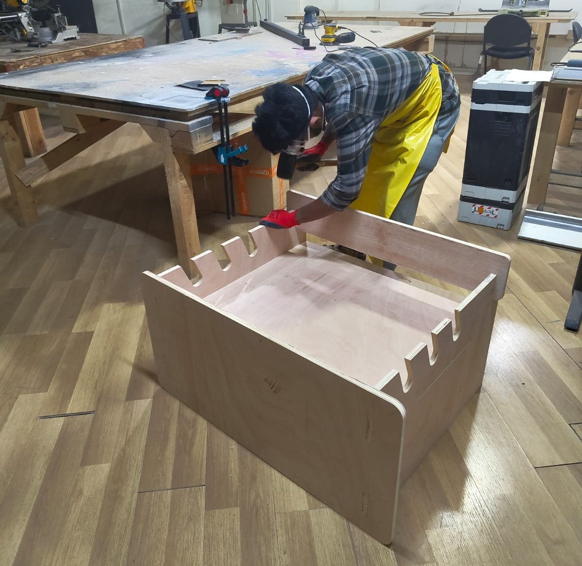
After finishing all the parts I started assembling the model. Our instructor Sibin helped me to assemble the model. As we tested the runout earlier in the group assignment and designed according to the values obtained the joints were perfect. Using rubber mallet I joined the parts.
 |
 |
Hero Shot
 |
 |
Conclusion
This week, I learned more about parametric design and how to operate the ShopBot machine. I also worked with VCarve software for CAM, tested runout in woodworking, and designed a table for the vinyl cutter in our lab.