Embedded Programming

Objectives for Week 4


Group Assignment

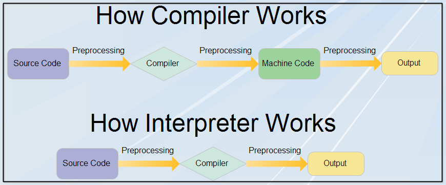
Compiler and Interpreter

Compiler

A compiler is a program that translates the entire source code of a programming language into machine code before the program is run. It checks the whole code for errors and, if none are found, generates an executable file (like .exe). This file can be run independently on any system without the compiler. Because the code is already translated, compiled programs run very fast. Compilers are commonly used in languages like C, C++, and Java (Java uses both compiler and interpreter).


Interpreter

An interpreter is a program that reads and executes the source code line by line. It does not create a separate executable file. Instead, it directly translates and runs each instruction as it reads it. If there is an error in the code, the interpreter stops immediately and shows the error, making it easier to debug. However, this method is usually slower than using a compiler because the translation happens every time the code runs. Languages like Python, JavaScript, and Ruby use interpreters.


Image taken from EComputerNotes.

This week, we explored different embedded systems and their development workflows. We used the XIAO RP2040 with both the Arduino IDE (C/C++) and Thonny (MicroPython) to compare compiled and interpreted programming. We also worked with the ATtiny1614 microcontroller using AVR toolchains and UPDI programming. In addition, we learned about FPGA controllers, focusing on hardware description languages and how they differ from microcontrollers by allowing hardware-level reprogramming. Finally, we tested the Raspberry Pi 5, running Linux, and used it for GPIO, I2C, and SPI tasks. These hands-on activities helped us understand the strengths and uses of each platform.

Microcontroller Toolchain Overview

Microcontroller Toolchain Components Programming Language IDE/Editor
RP2040 Arduino Core for RP2040, GCC, avrdude C/C++ Arduino IDE
RP2040 MicroPython Firmware, REPL MicroPython Thonny
ATtiny1614 ATTinyCore, avrdude C/C++ Arduino IDE
ATtiny84 ATTinyCore, avrdude C/C++ VS Code + PlatformIO
ESP32 ESP–IDF, GCC, esptool C/C++ VS Code + PlatformIO
STM32F303RE STM32Duino Core, GCC, STLink C/C++ Arduino IDE
Raspberry Pi 5 Linux-based toolchain (GCC, Python, etc.) Python, C, C++ VS Code, Thonny, Terminal

Group Assignment Link.

Raspberry Pi Pico

For this week's assignments, I selected the Raspberry Pi Pico as my development board and used Wokwi to simulate the program I wrote. I experimented with MicroPython for programming.

Image taken from Mouser Electronics.

RP2040

The Raspberry Pi Pico is powered by the RP2040 microcontroller, a dual-core Arm Cortex-M0+chip developed by Raspberry Pi. I referred to the RP2040 datasheet to gain a basic understanding of the chip.

Specification

Image taken from Cytron Marketplace.

Feature Description
Processor Dual-core ARM Cortex-M0+
Clock Speed Up to 133 MHz (default 125 MHz)
On-chip SRAM 264 KB (divided into 6 banks)
External Flash Support Up to 16 MB via QSPI (typically 2 MB onboard on Pico)
DMA Channels 12 independent DMA channels
PIO (Programmable I/O) 2 PIO blocks, 4 state machines each, for custom protocol handling
Timers 2x hardware timers + 8x PWM channels
GPIO 30 GPIOs (4 can be analog inputs)
ADC 3x 12-bit ADC channels + 1 internal temperature sensor
USB USB 1.1 controller with device and host support
I/O Interfaces 2x SPI, 2x I2C, 2x UART, PWM, ADC, PIO
Package 7×7 mm QFN-56 with 40 GPIO pins
Power Supply Range 1.8V – 3.3V I/O, with integrated LDO and USB regulator
Operating Temperature -40°C to +85°C
Boot Mode USB mass storage bootloader for easy flashing
Internal Clock Built-in crystal-less USB operation with optional external crystal support

The datasheet of RP2040 can be downloaded from here.

A system overview of RP2040 chip.
Raspberry pi pico pin out.

Wokwi

This week's assignment involves programming a board and simulating its functionality using a simulation software, eliminating the need for a physical board. One popular tool for this task is Wokwi, an online simulator for embedded systems. Wokwi supports various microcontrollers, including Arduino, ESP32, ESP8266, and RISC-V, allowing users to write and test code directly in the browser. It provides a visual interface to connect components like LEDs, sensors, LCD displays, and motors, enabling real-time simulation of embedded projects. Additionally, Wokwi allows users to debug their code, analyze serial output, and adjust circuit connections without requiring any hardware.


Creating a New Project

  1. I searched for Wokwi in my browser and clicked on the first link that appeared. After signing in, I selected "My Projects" and started a New Project.


  2. Then, I selected Raspberry Pi Pico and chose the MicroPython template for the simulation.


Programming

MicroPython is used to program the Raspberry Pi Pico, and the simulation is performed in Wokwi, eliminating the need for any physical components.

I experimented with some basic examples to understand the fundamentals of programming.

1. Hello World


import time
time.sleep(.2)
print("Hello World!")

Explanation


2. Blink Onboard LED


from machine import Pin
from utime import sleep 
led = Pin(25,Pin.OUT) #define on board LED 
while True: 
    led.toggle() #toggle state of LED 
    sleep(1) #delay for 1 second

Explanation


3. External LED and Push Button

In the previous two programs, I used only the Raspberry Pi Pico to control the onboard LED. Now, I have connected an external LED, a resistor, and a push button to the Pi Pico to control the LED using the button. The resistor is used to limit the current flow to the LED, preventing damage.

The components can be inserted from the + icon.

Taken reference from here.

I attempted to modify the code I obtained from the above link. Comparing it with the Blink Onboard LED code, I removed the "if-else" loop from the original code and rewrote it using an "if" condition and "led.toggle()". To my surprise, the code worked perfectly, and I got the expected output.

The push button is connected between GPIO0 and GND. The positive terminal of the LED is connected to GPIO1, while the negative terminal is connected to GND. A resistor is placed in series with the LED to limit the current flow.

from machine import Pin
from utime import sleep
button = Pin(0, Pin.IN, Pin.PULL_UP)
led = Pin(1,Pin.OUT) #define on board LED
while True:
    print(button.value())
    if button.value()==0: 
        led.toggle() #toggle state of LED
        sleep(1) #delay for 1 second

Explanation


4. External LED and Ultrasonic Sensor

I used an LED and an ultrasonic sensor to measure distance. If the sensor detects a value of 200 cm or less, the LED starts blinking. Otherwise, the LED remains off. Refered the Connection of Ultrasonic Sensor to Raspberry Pi Pico and the Code from here.

I took the code from the above link and wired the circuit as mentioned in the documentation. I simulate in Wokwi and the code works perfectly.

Wiring of Ultrasonic Sensor.

Then I imported an LED and a resistor and wired it like the External LED and Push Button project. I wnt to turn ON the LED when the distance is 200cm or below and turn it OFF when the value is above 200cm. When refering the code while recieved for External LED and Push Button I saw if-else loop is used for turning ON and OFF led. So I tried "if-else" loop and I got the output.


from machine import Pin, time_pulse_us
import time

SOUND_SPEED=340 #Speed of Sound in air.
TRIG_PULSE_DURATION_US=10

trig_pin = Pin(15, Pin.OUT) # GP15 pin of the Pico
echo_pin = Pin(14, Pin.IN)  # GP14 pin of the Pico
led = Pin(1, Pin.OUT)
while True:

    # Prepare the signal
    trig_pin.value(0)
    time.sleep_us(5)
    # Create a 10 µs pulse
    trig_pin.value(1)
    time.sleep_us(TRIG_PULSE_DURATION_US)
    trig_pin.value(0)

    ultrason_duration = time_pulse_us(echo_pin, 1, 30000) # Returns the propagation time of the wave (in µs)
    distance_cm = SOUND_SPEED * ultrason_duration / 20000

    print(f"Distance : {distance_cm} cm")
    time.sleep_ms(500)
    if distance_cm <=200:
        led.value(1)
    else:
        led.value(0)

Explanation


After the simulation I tried it the actual hardware.

I took Xiao ESP32 C6 and Ultrasonic Sensor and connected it to a bread board. I used ChatGPT for programming. I refered Randomnerdtutorials for the reference.

I wired like was said in the above mentioned documentation

Image taken taken from Randomnerdtutorials.

Connections


Initially I tested with ultrasonic sensor to read its value on serial monitor. The code on the documentation is used for this.

I used Arduino IDE for programming. Which we used in our group assignment.

Got the output and it looks like this.


Code

  const int trigPin = 2;
const int echoPin = 21;

//define sound speed in cm/uS
#define SOUND_SPEED 0.034
#define CM_TO_INCH 0.393701

long duration;
float distanceCm;
float distanceInch;

void setup() {
  Serial.begin(115200); // Starts the serial communication
  pinMode(trigPin, OUTPUT); // Sets the trigPin as an Output
  pinMode(echoPin, INPUT); // Sets the echoPin as an Input
}

void loop() {
  // Clears the trigPin
  digitalWrite(trigPin, LOW);
  delayMicroseconds(2);
  // Sets the trigPin on HIGH state for 10 micro seconds
  digitalWrite(trigPin, HIGH);
  delayMicroseconds(10);
  digitalWrite(trigPin, LOW);
  
  // Reads the echoPin, returns the sound wave travel time in microseconds
  duration = pulseIn(echoPin, HIGH);
  
  // Calculate the distance
  distanceCm = duration * SOUND_SPEED/2;
  
  // Convert to inches
  distanceInch = distanceCm * CM_TO_INCH;
  
  // Prints the distance in the Serial Monitor
  Serial.print("Distance (cm): ");
  Serial.println(distanceCm);
  Serial.print("Distance (inch): ");
    Serial.println(distanceInch);
  delay(1000);
}

Then I tried to turn ON and OFF the onboard LED of the Xiao ESP32 C6 based on the ultrasonic readings.


  const int trigPin = 2;
const int echoPin = 21;
const int ledPin = 15; // Onboard LED on XIAO ESP32C6

#define SOUND_SPEED 0.034
#define CM_TO_INCH 0.393701

long duration;
float distanceCm;
float distanceInch;
void setup() {
  Serial.begin(115200);
  pinMode(trigPin, OUTPUT);
  pinMode(echoPin, INPUT);
  pinMode(ledPin, OUTPUT); // Set LED pin as output
}

void loop() {
  // Clear the trigPin
  digitalWrite(trigPin, LOW);
  delayMicroseconds(2);

  // Send 10us pulse to trigger
  digitalWrite(trigPin, HIGH);
  delayMicroseconds(10);
  digitalWrite(trigPin, LOW);

  // Read the echo time
  duration = pulseIn(echoPin, HIGH);

  // Calculate distance in cm and inch
  distanceCm = duration * SOUND_SPEED / 2;
  distanceInch = distanceCm * CM_TO_INCH;

  // Print distances
  Serial.print("Distance (cm): ");
  Serial.println(distanceCm);
  Serial.print("Distance (inch): ");
  Serial.println(distanceInch);

  // Control LED based on distance
  if (distanceCm < 10) {
    digitalWrite(ledPin, HIGH); // Turn ON LED
  } else {
    digitalWrite(ledPin, LOW); // Turn OFF LED
  }

  delay(1000);
}

ChatGPT Promt: This is a working code for ultrasonic sensor(The previous code). While the value of cm is above 10 the on board LED on the xiao esp32c6 needed to be turned ON and while its below 10 turn OFF.

Hero Shot

As a beginner in programming, writing code was initially challenging. However, after experimenting with various programs, I successfully turned on an LED based on input values from an ultrasonic sensor. Seeing the program run correctly was a highly satisfying experience.


Conclusion

This week, I learned about microcontrollers and processors, along with how to program them. I focused on the RP2040 microcontroller, explored its datasheet, and examined its specifications. Additionally, I experimented with the Wokwi simulator for circuit wiring, programming, and simulation. For coding, I primarily used MicroPython and worked with the Raspberry Pi Pico as my main microprocessor.


ChatGPT is used for paraphrasing.

References


Downloads