Computer Controlled Cutting
Objectives for Week 3
- Cut something on the vinylcutter
- design, lasercut, and document a parametric construction kit
- Do lab's safety training
- characterize lasercutter's focus, power, speed, rate, kerf, joint clearance and types
Individual Assignment
Group Assignment:
Group Assignment
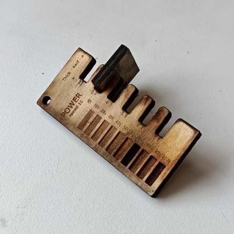
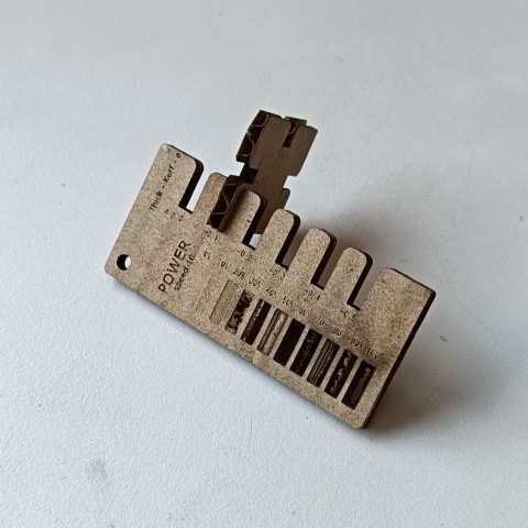
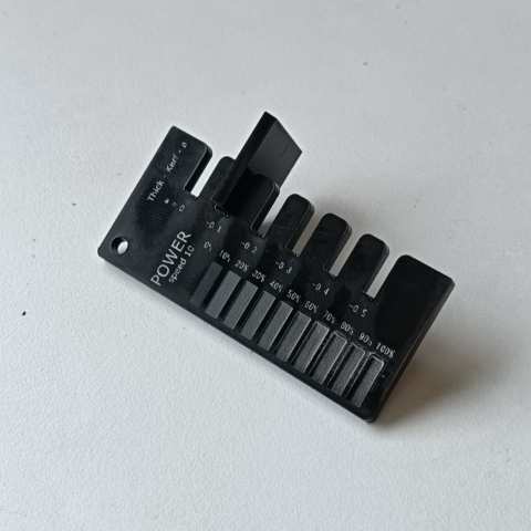
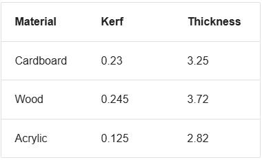
In this week's group assignment, we learned about lab safety and the use of PPE equipment. We then explored the laser cutter, understanding kerf and its parameters for different materials. After determining kerf values, we designed a jig to find the correct clearance for press-fit joints in various materials. The values obtained were later used to design a parametric construction kit. This assignment also helped us develop teamwork skills.
After completing the group assignment, I gained a clear understanding of what kerf is in the context of laser cutting. I learned that kerf refers to the width of material removed by the laser beam as it cuts through the material. This gap is created due to the heat of the laser vaporizing or burning the material along the cutting path. I also realized that the kerf can vary depending on factors such as the type and thickness of the material, the laser power, speed, and focus. Accurately accounting for kerf is essential in laser cutting to ensure that parts fit together properly and maintain precise dimensions.
 |
 |
 |
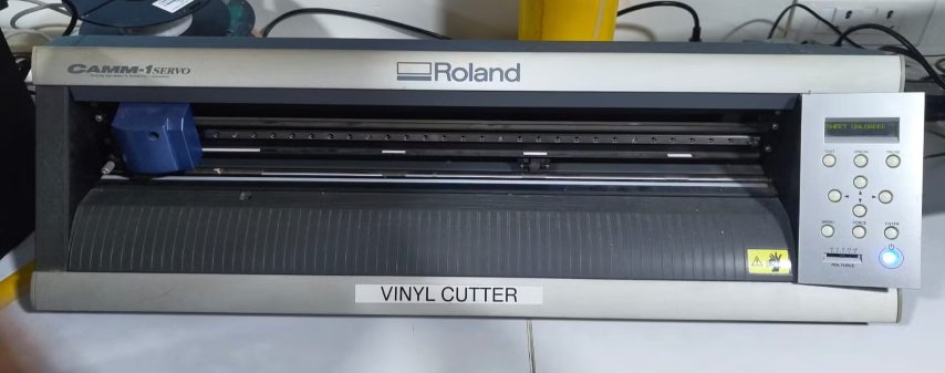
1. Vinyl Cutting
Vinyl cutting is the process of using a vinyl cutter machine to create shapes and letters from sheets of vinyl. You design what you want on a computer, upload it to the machine, and it uses a sharp blade to cut out the shapes from the vinyl. This is commonly used to make signs, decals, and other things.
 |

|
Specification
| Cutting Width | 610 mm |
| Cutting Speed | Up to 250 grams |
| Resolution | 0.0127 mm |
| Dimensions | 855 x 315 x 240 mm |
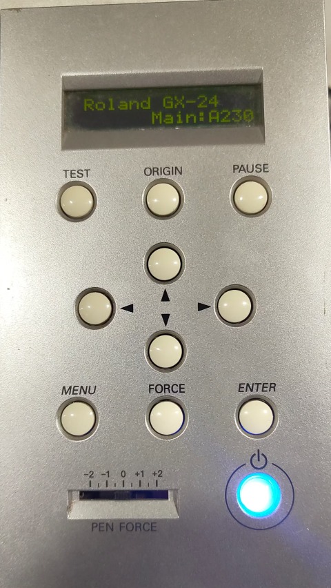
The Roland GX-24 Vinyl cutter which we used in our lab is a Passive Vinyl cutter. The Active vinyl cutters have a dedicated servo mechanism to rotate the blade while the passive vinyl cutters doesn’t have the servo mechanism.
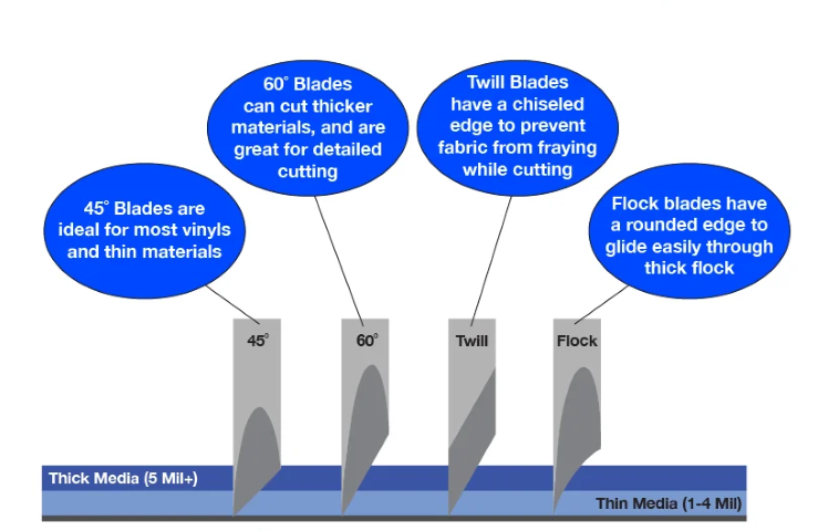
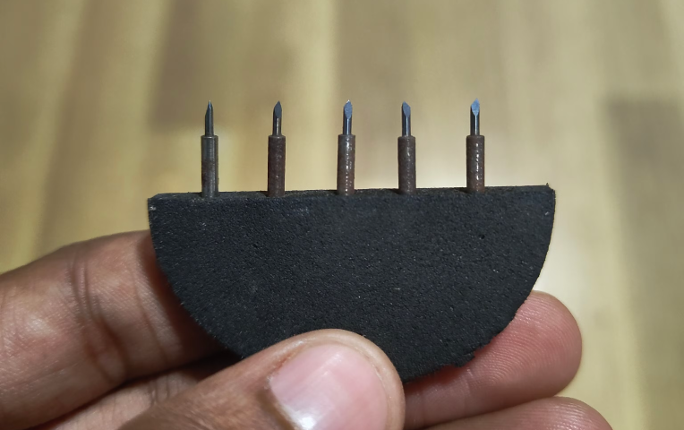
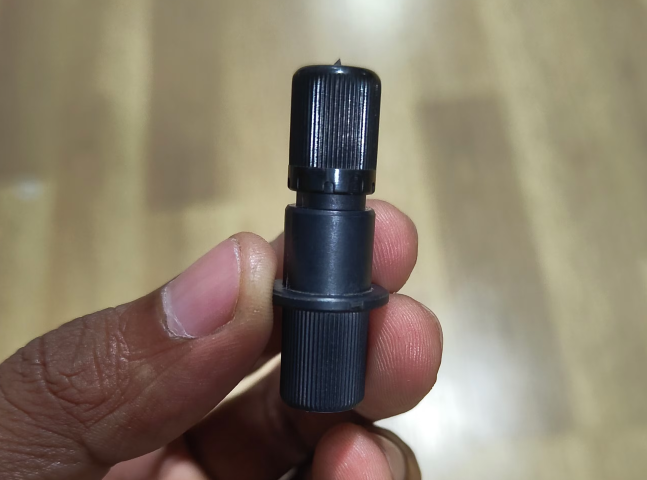
A vinyl cutter uses a special blade. This blade is often very thin and sharp, and it's designed to cut through vinyl without damaging it.
The tool we used here and the tool holder is below.
 |
 |
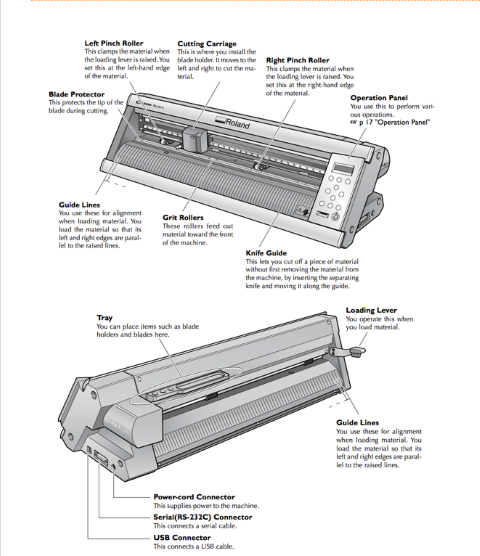
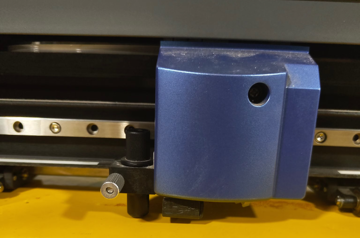
The tool holder is then placed in the tool carriage of the machine. The tool carriage moves the tool to the desired place to cut the vinyl according to our design.
Setting the Machine
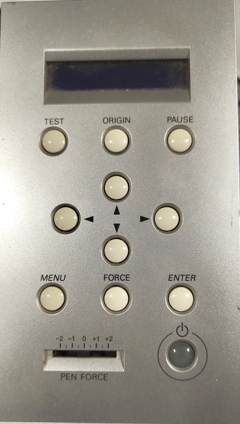
- Press the Power button to turn ON the machine.
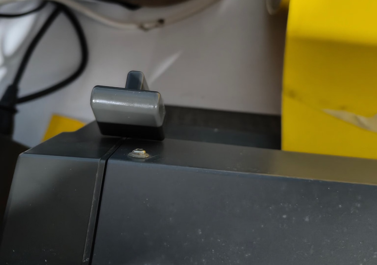
- Unlock the lever in the back side of the machine to Unlock the rollers which are holding and guiding the vinyl.
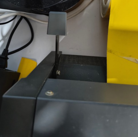
The lever is disengaged. 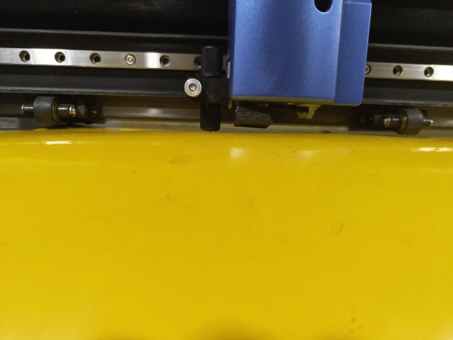
The rollers are lifted from the vinyl.
there is a gap visible below the rollers. - Load the vinyl and engage the lever so that the rollers hold the vinyl in position.
The lever is engaged. 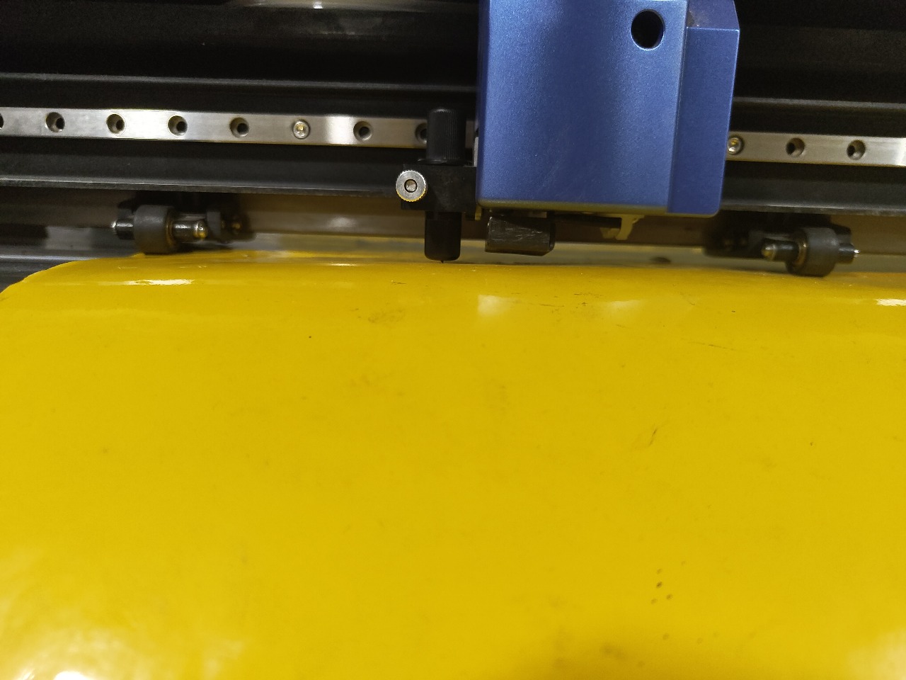
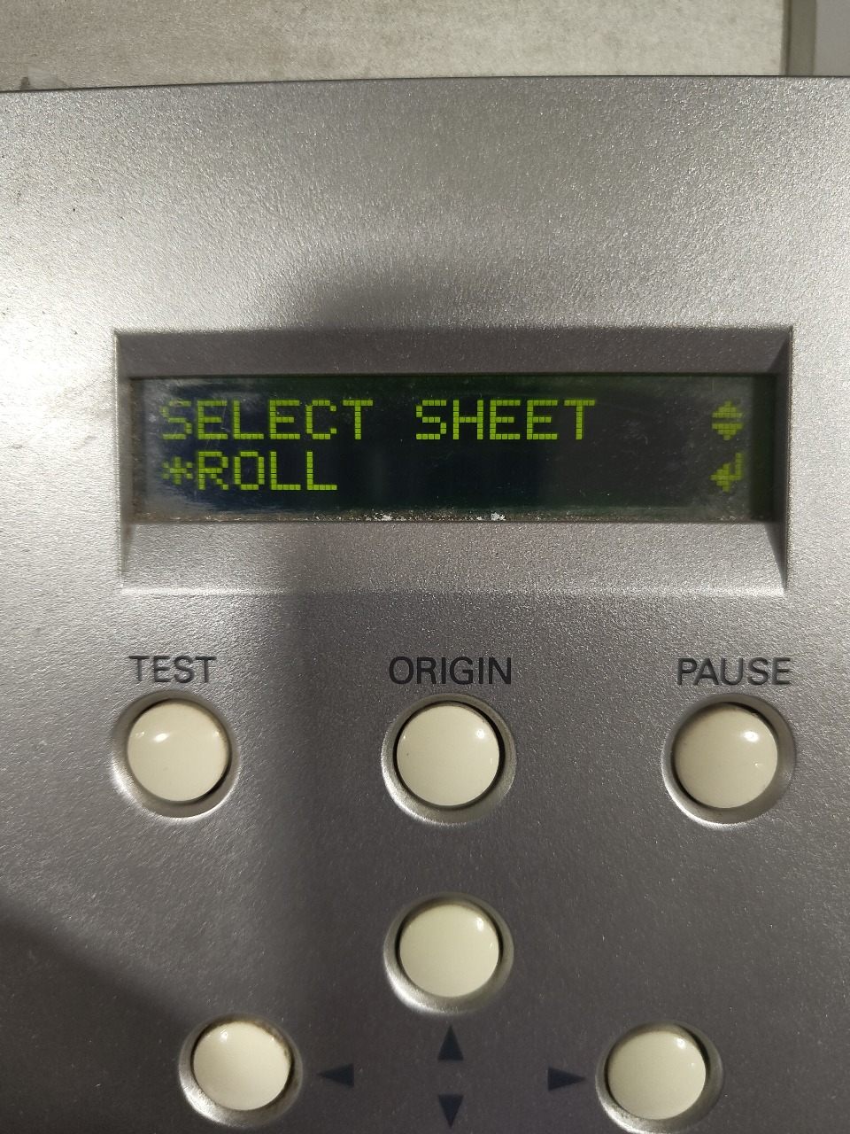
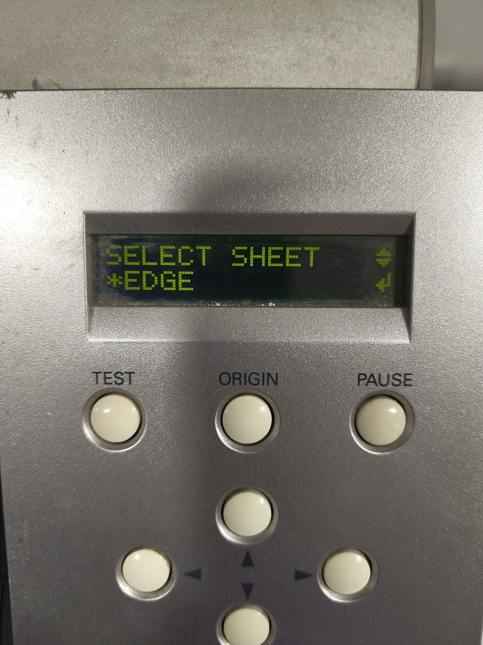
The rollers are firmly gripped above the vinyl and there is no gap between the rollers and vinyl. - The machine asks which type of vinyl we are going to load Roll, Piece or Edge. Select the option accordingly and select Enter.

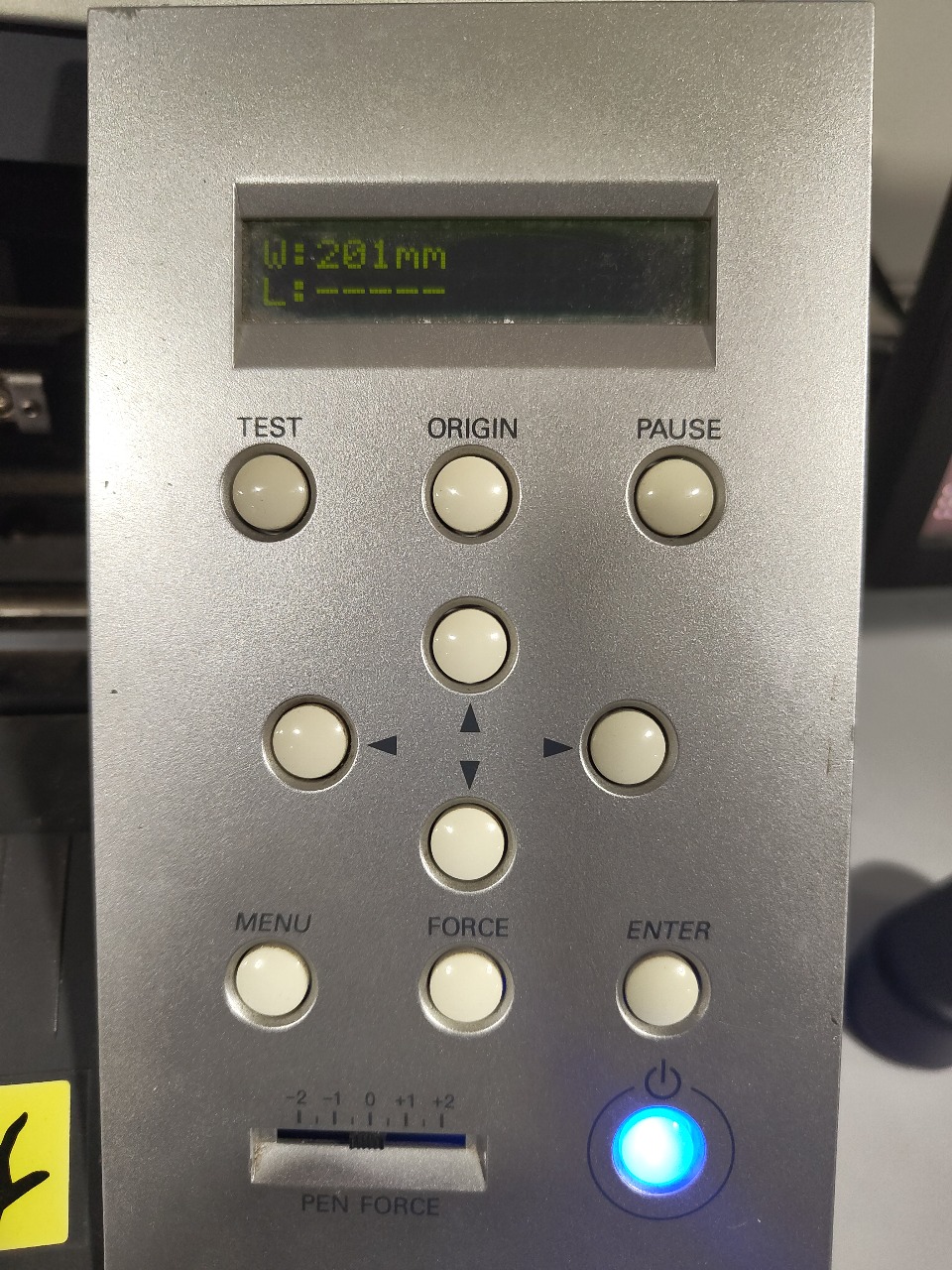
- The machine measure the dimension the vinyl and it is displayed in the display.
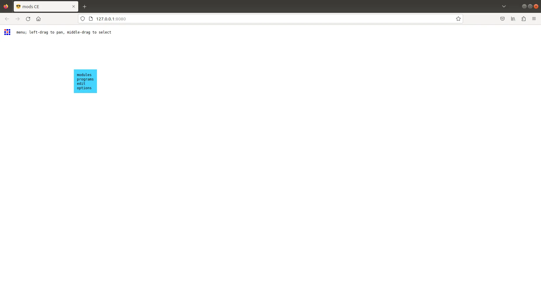
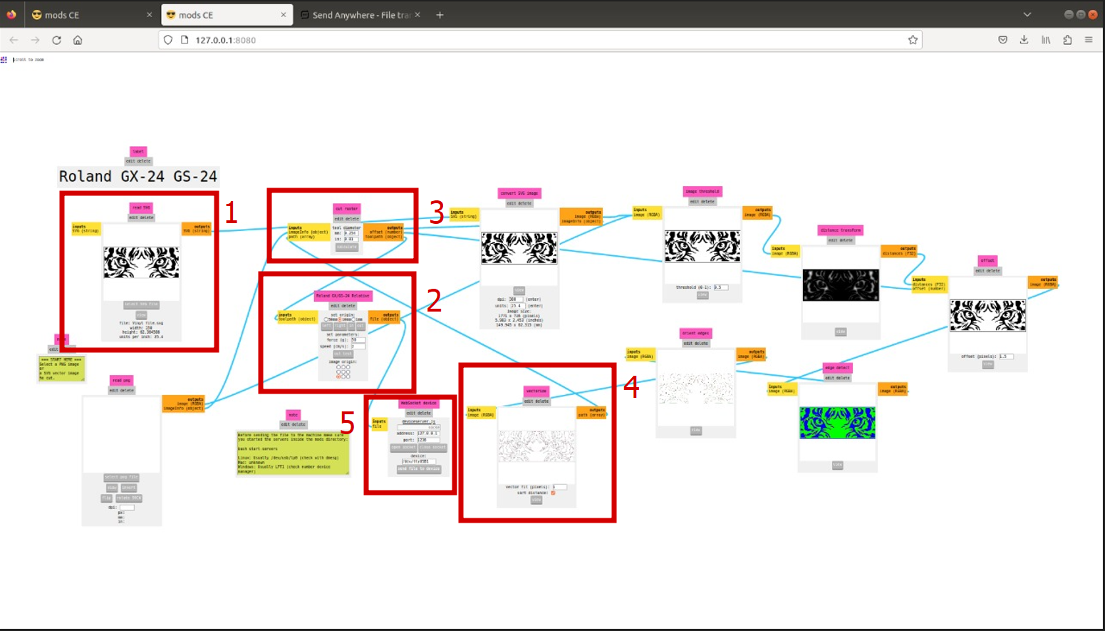
Fab Mods
Fab Mods are a set of software tools designed for personal fabrication, specifically for use with machines commonly found in Fab Labs. They help with designing, generating toolpaths, and controlling the machines.
Design For Vinyl Cutting
I used Inkscape for Design the files for vinyl cutting. I downloaded a Tiger image from internet.
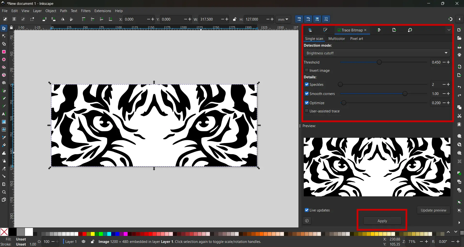
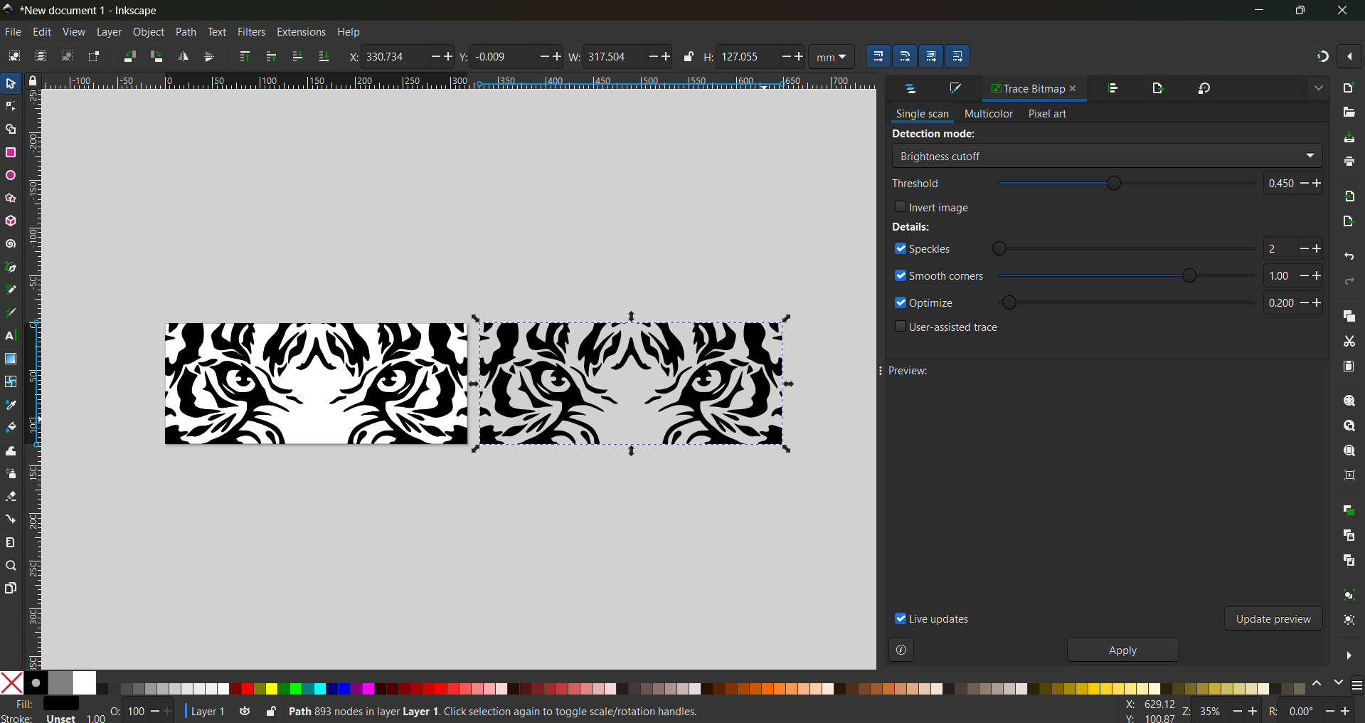
I imported the image into Inkscape, but since it was a raster file, I needed to convert it into a vector format. To achieve this, I used the "Trace Bitmap" tool with the "Brightness Cutoff" option, applying the specified parameters. After converting the image to a vector file, I exported it as an `.svg` file, making it compatible for use in the Mods software.
 |
 |
Cutting the image
- The machine is set up according to the above mentioned steps.
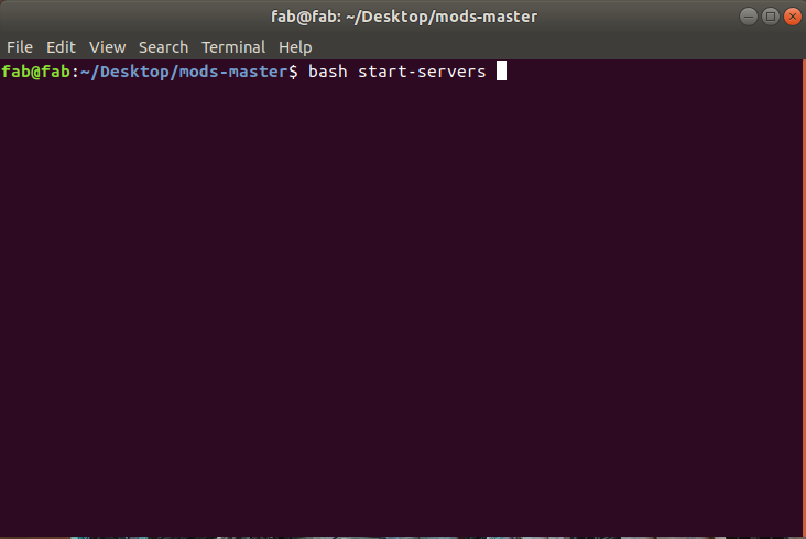
- In the Computer a open the Fab Mods by right click the folder named mods-master and open in terminal.
- In terminal type bash start- servers.
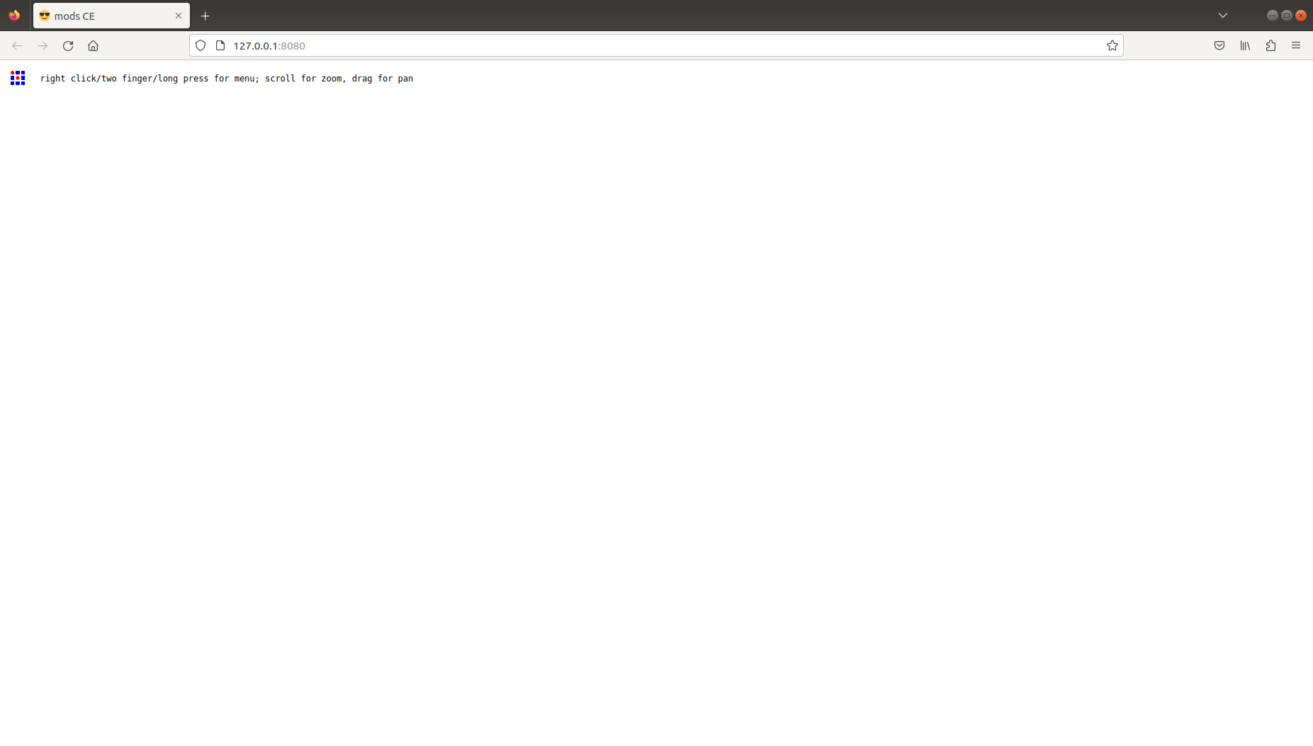
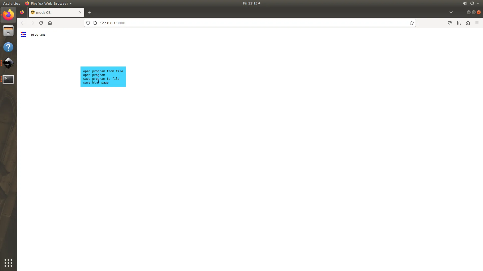
- The fab mods will open in the browser. Right click on the browser to continue.
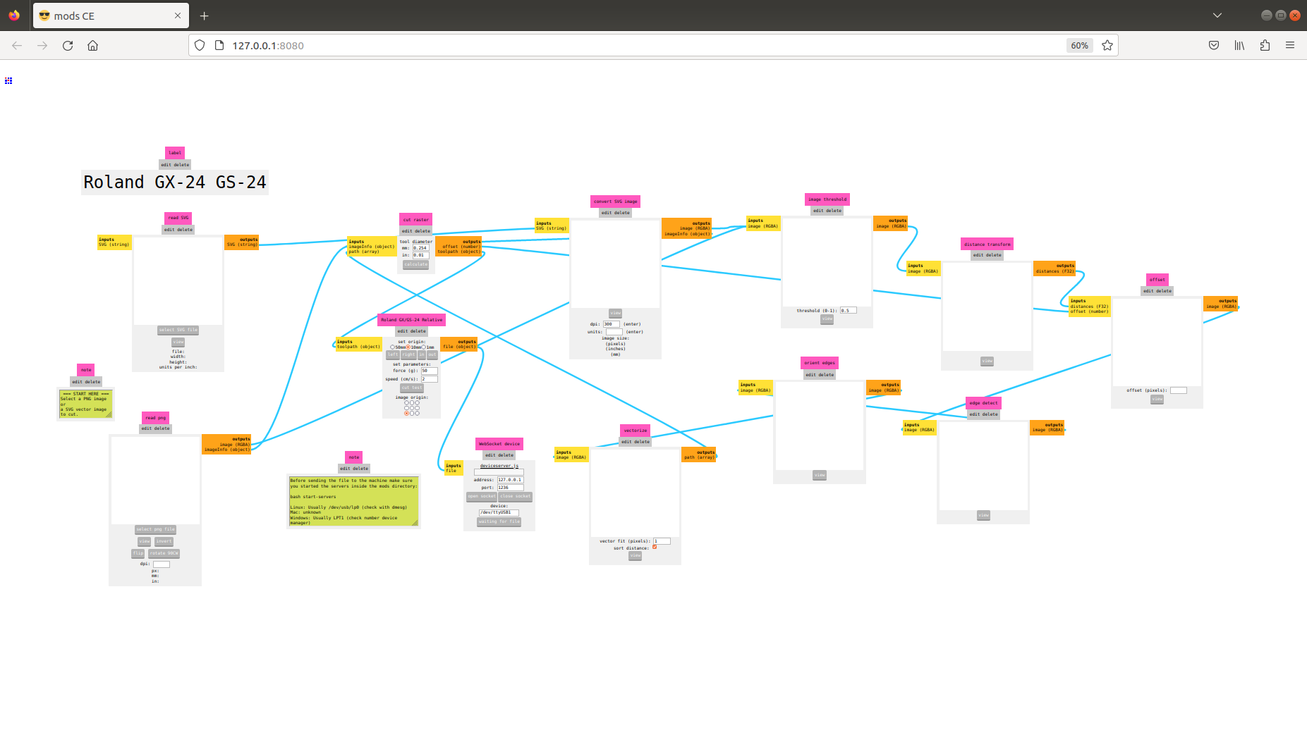
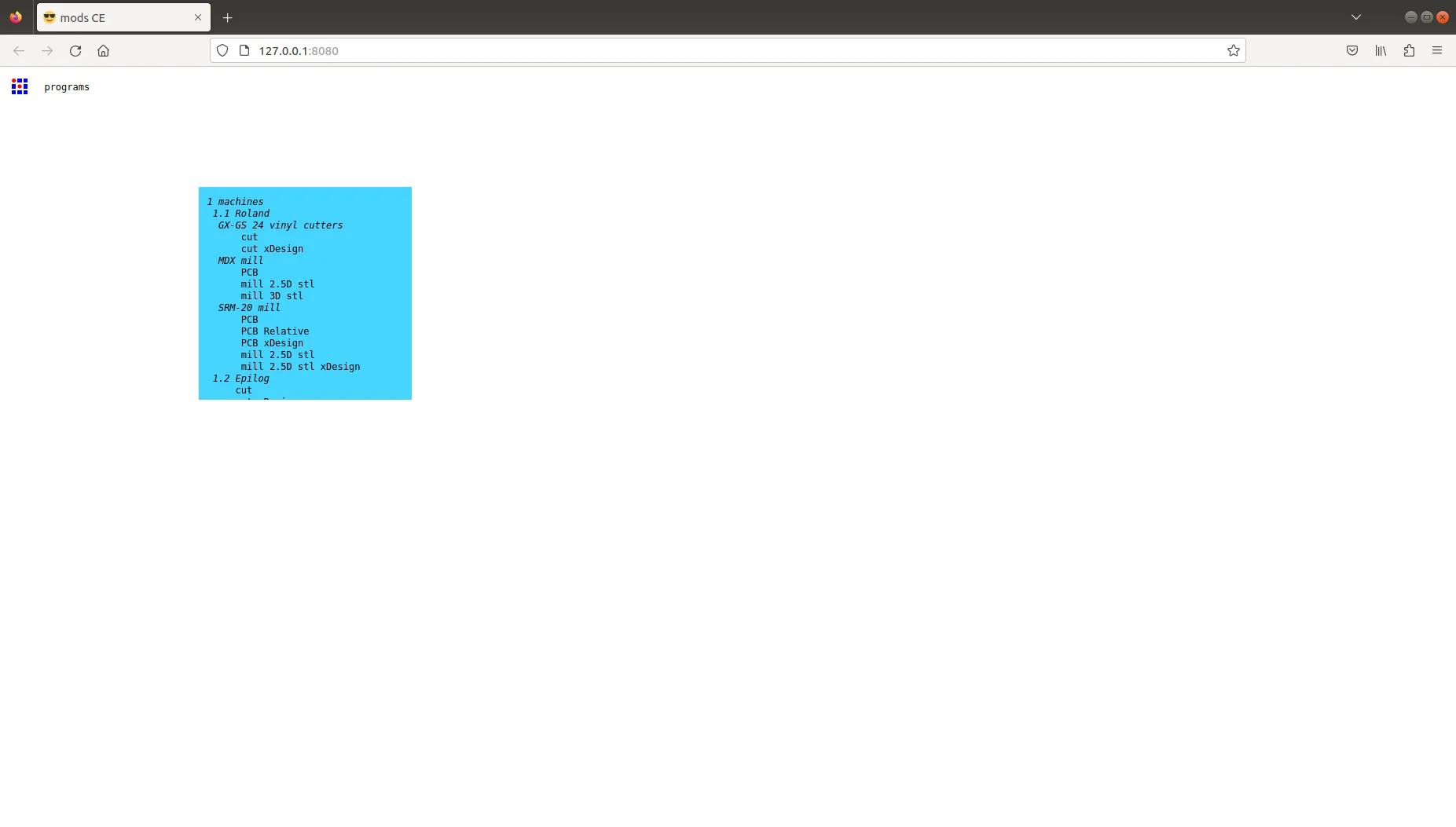
- Select programs →open programs→ cut (GX- GS 24 vinyl cutters).
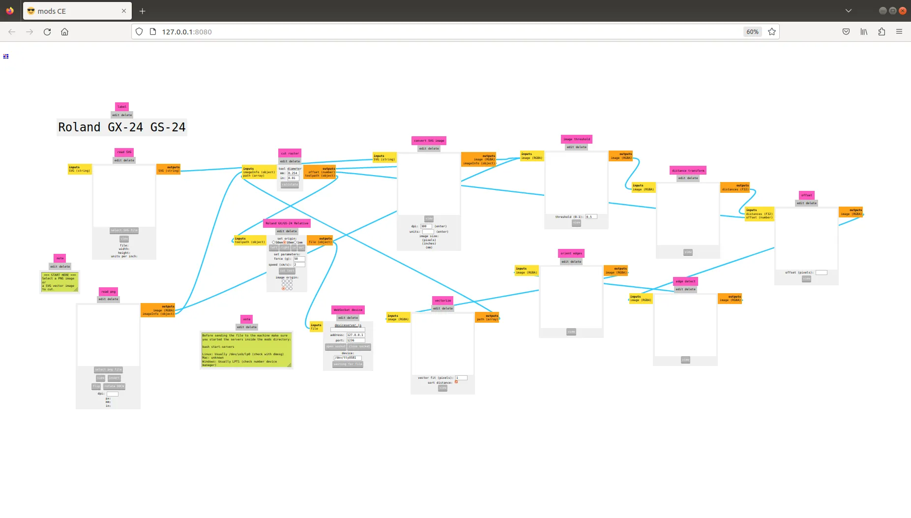
- Load the .svg and set origin, cutting speed, force and press calculate. Then confirm the tool path and sent the program to the machine.
 |
 |
 |
 |
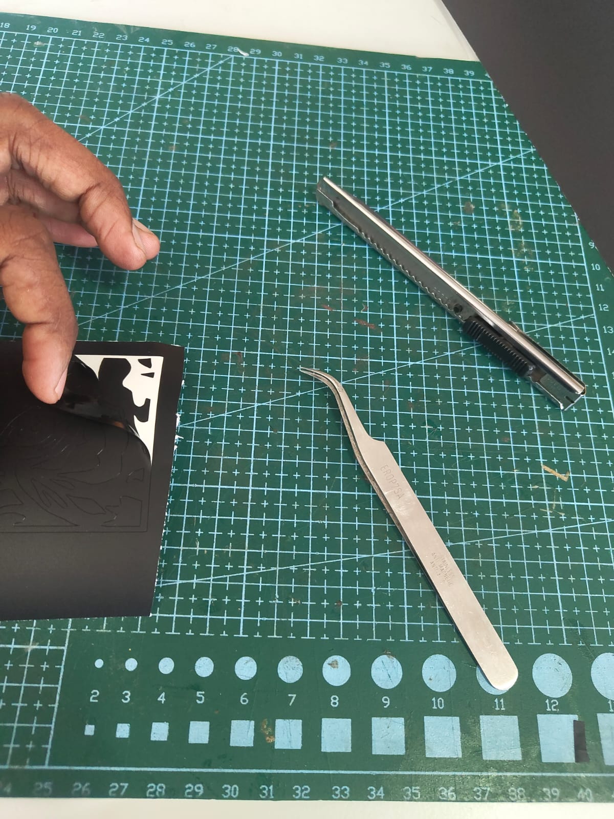
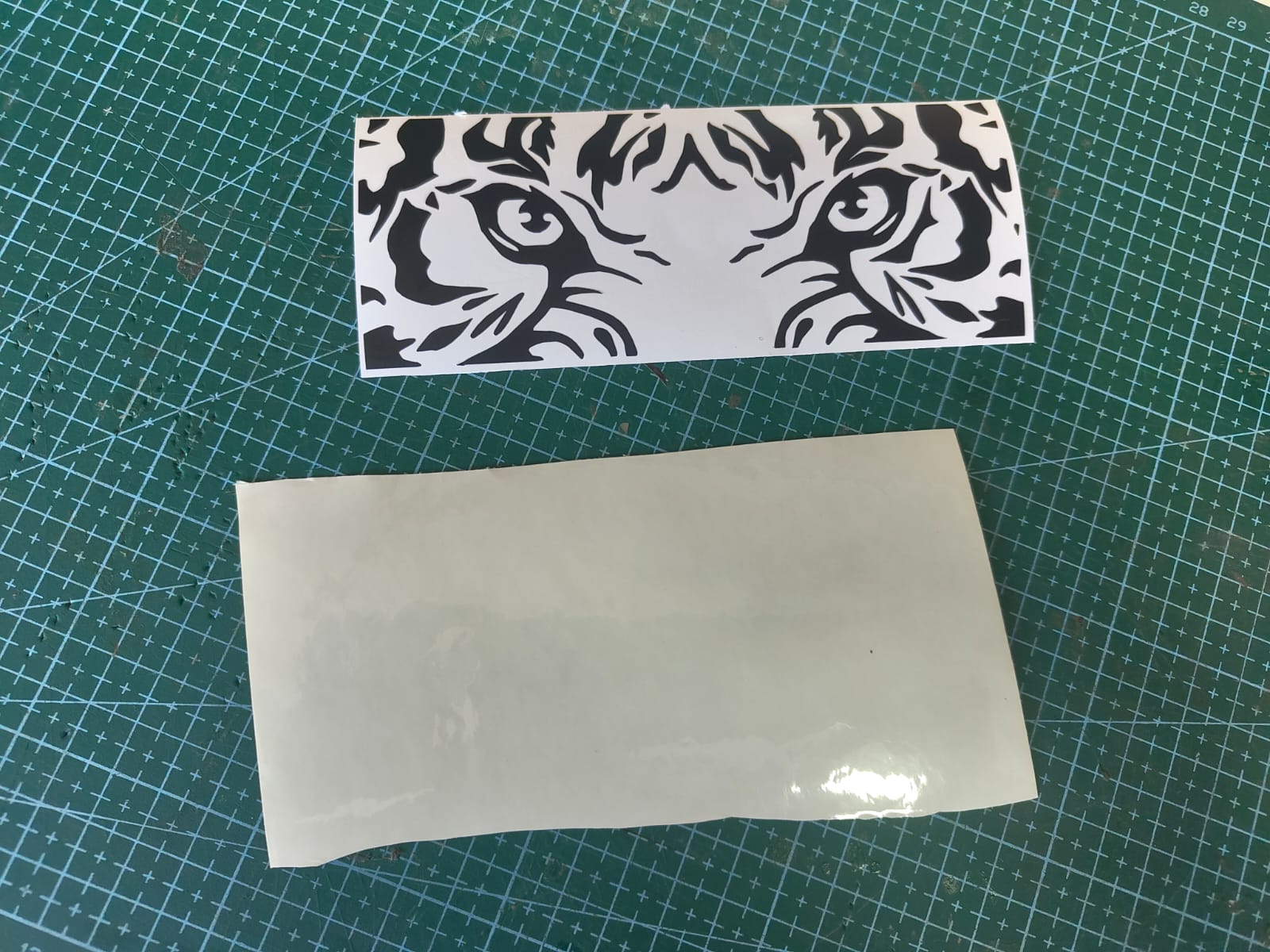
Post Processing
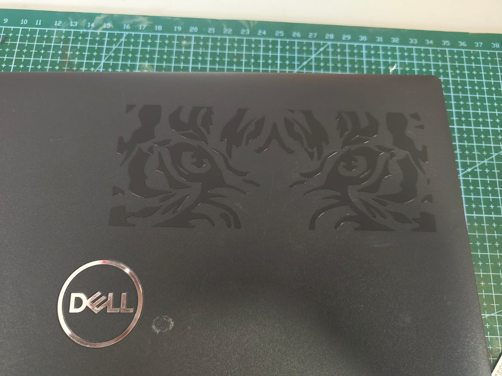
I used tweezers to remove the excess vinyl. Then, with the help of transfer paper, I applied the cut vinyl image onto my laptop.
 |
 |
 |
 |
Parametric Design
Parametric design is a fancy way to say "designing with rules." It's like building a house with a set of instructions. You change the instructions, and the house changes. It's used in many areas like building houses and making products.
Press Fit Construction Kit
I designed the models for my press fit construction kit based on the data I received during the group assignment. I designed the model using parametric design in fusion 360.
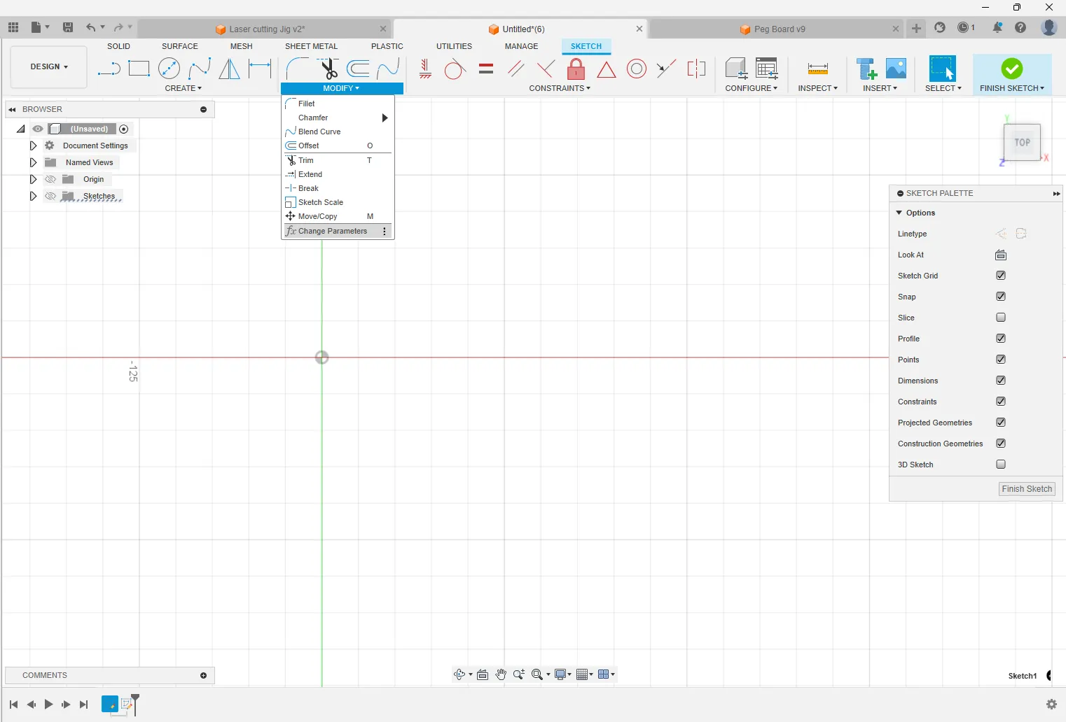
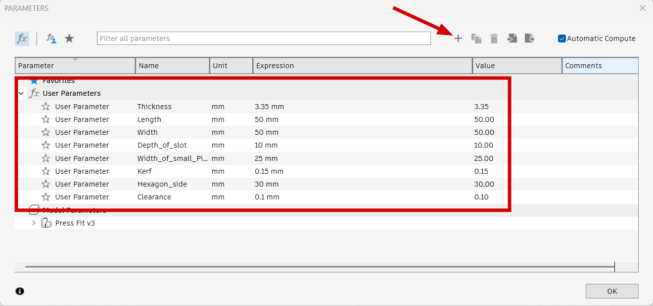
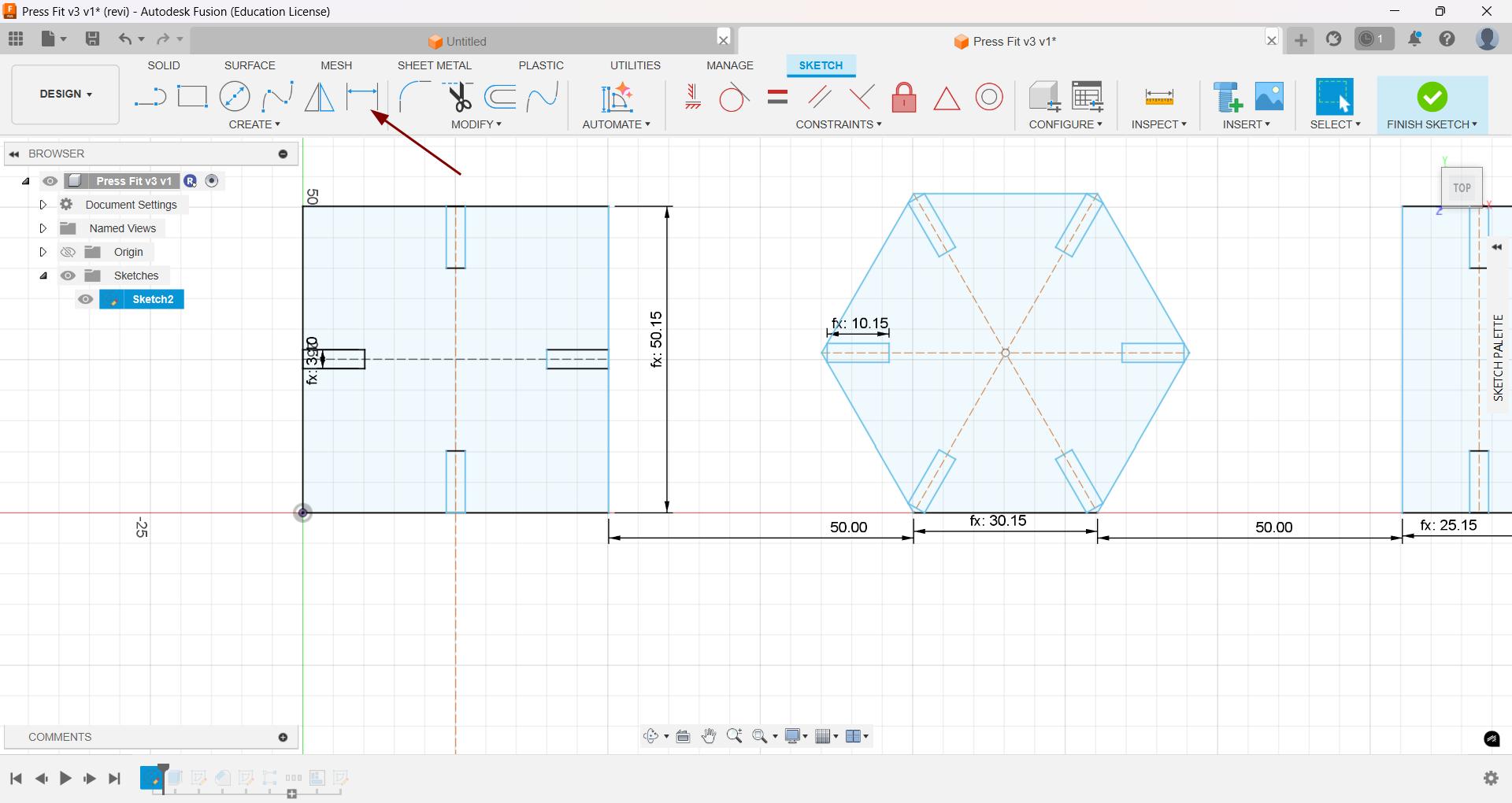
- Initially I opened the Fusion 360 and set all the parameters which I needed in the design.
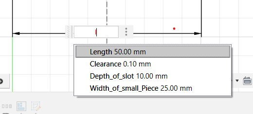
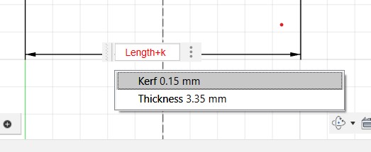
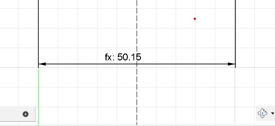
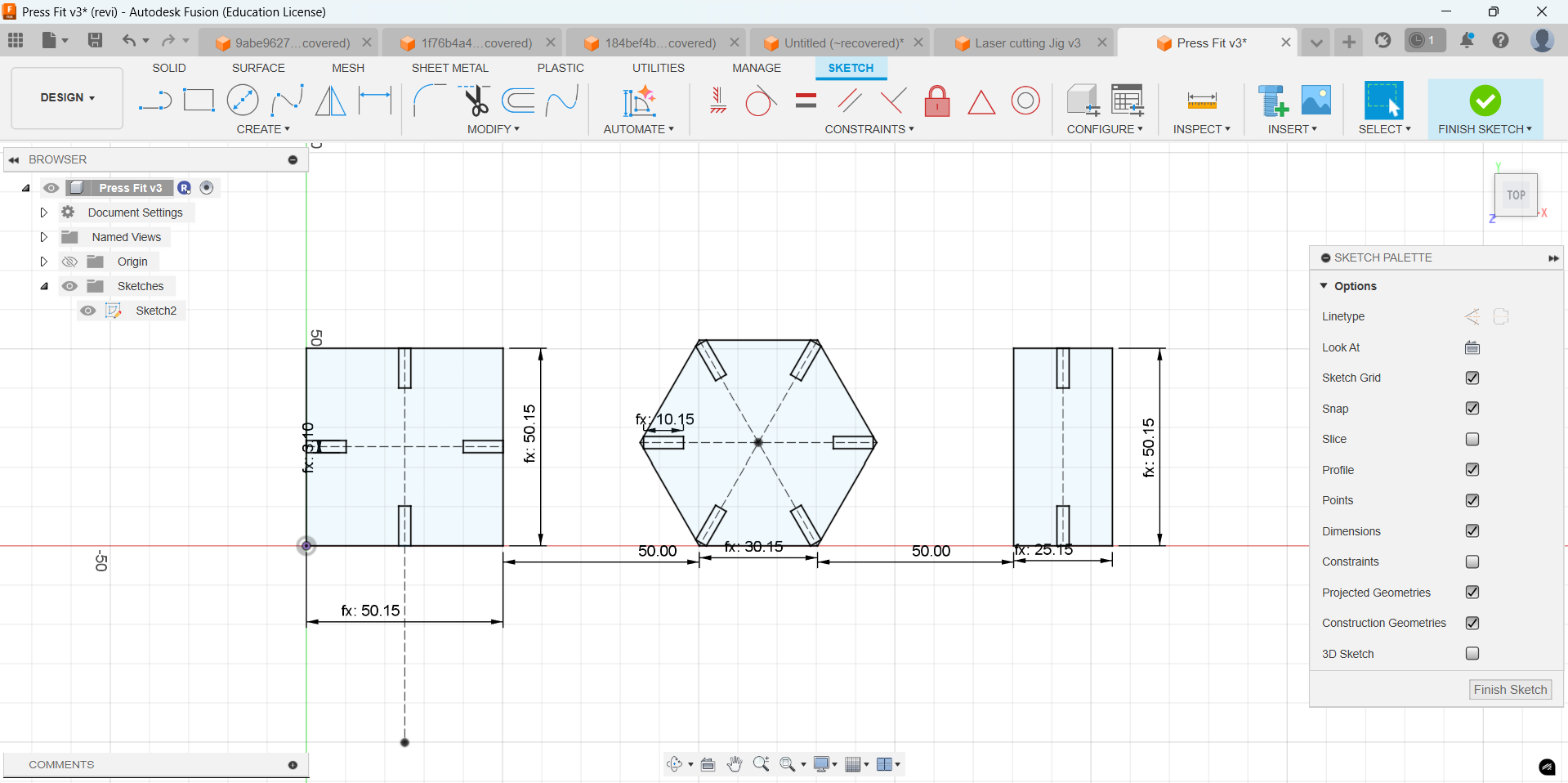
- Created a new sketch and sketched the shapes for the construction and applied all the parameters which I preset. The side of the square I want is 50 mm and I set it as Length in parameter and I needed to add the Kerf. So for that select the dimension initially search for length parameter and kerf parameter and add them as the value of dimension. Just type the first letter of the parameter and it will display as a list there.
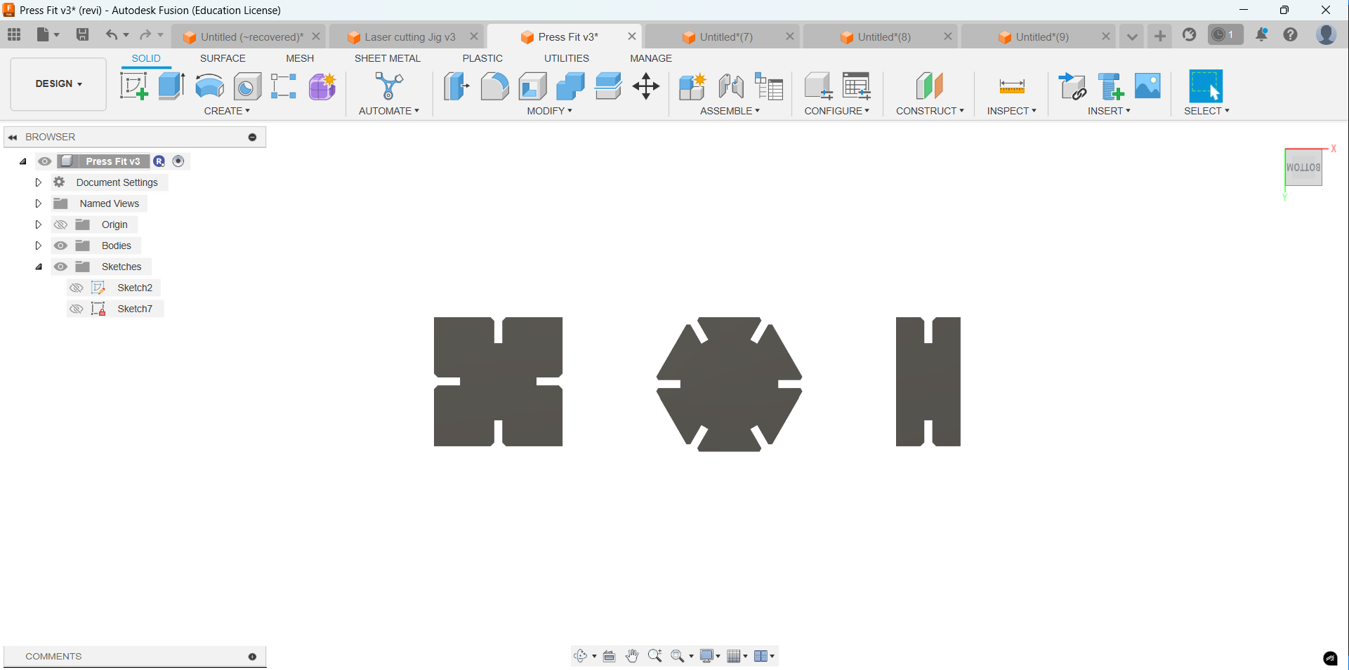
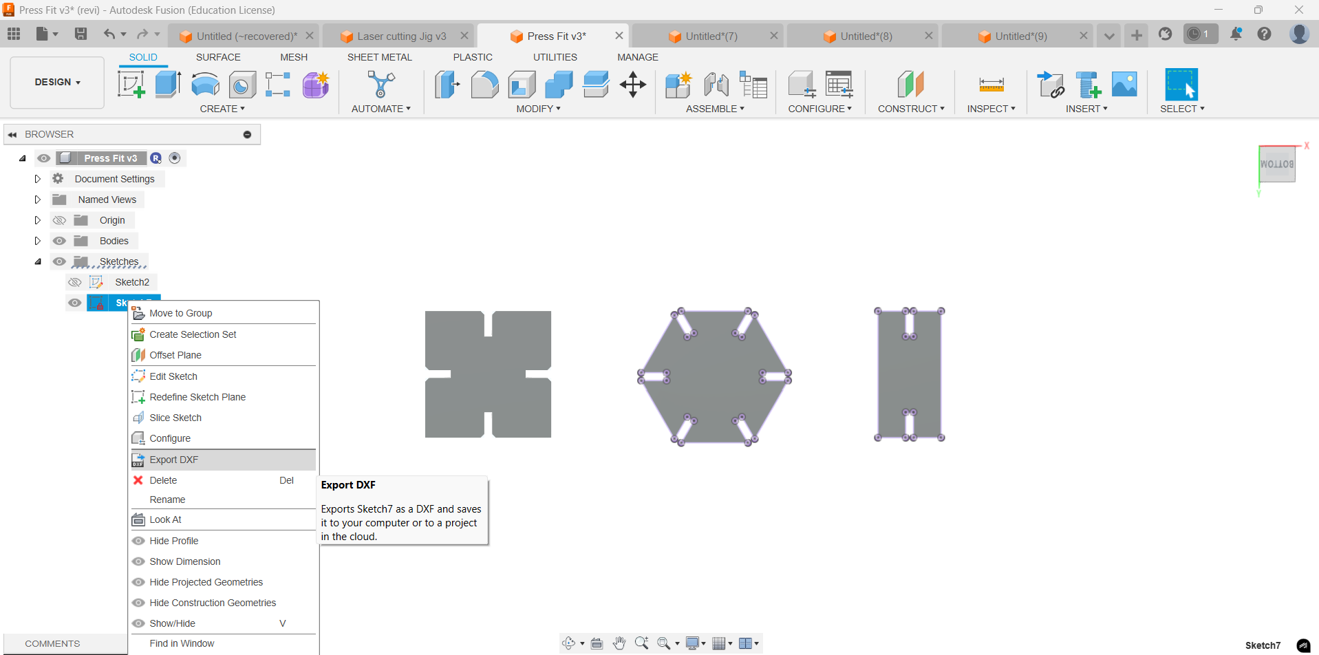
- For exporting the 2D sketch easily with out affecting the constrains I extruded the design and projected the faces which I am going to cut.
- Projected the faces and saved the sketch as .dxf format.
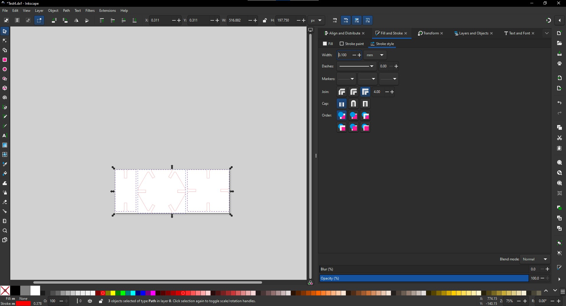
- I cut the pieces to test the fitment. For that loaded the image to inkscape and changed the stroke color to red aand stroke width to 0.1mm. Send it to the Job Control software.
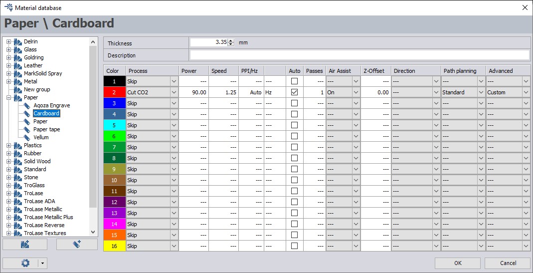
- Changed the parameters shown in the image and cut it.
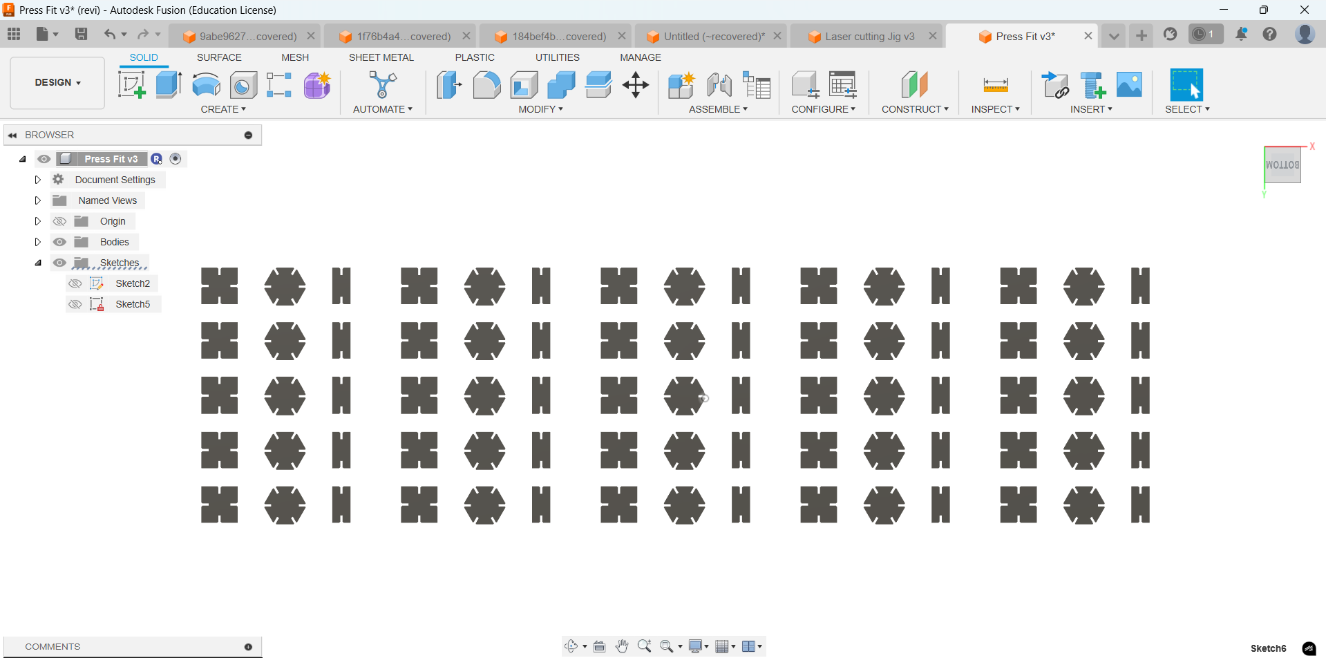
- I used a rectangular pattern to multiply the pieces to get 25 in total.
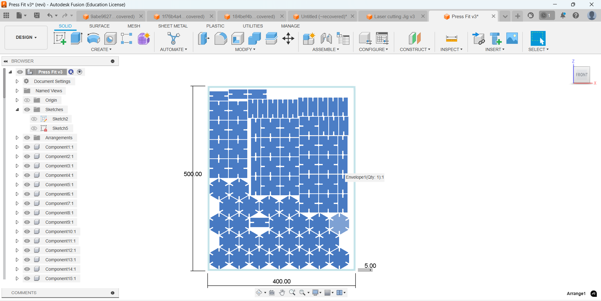
- Then, I arranged the shapes, created a new sketch, projected all faces, and exported the sketch in .dxf format.
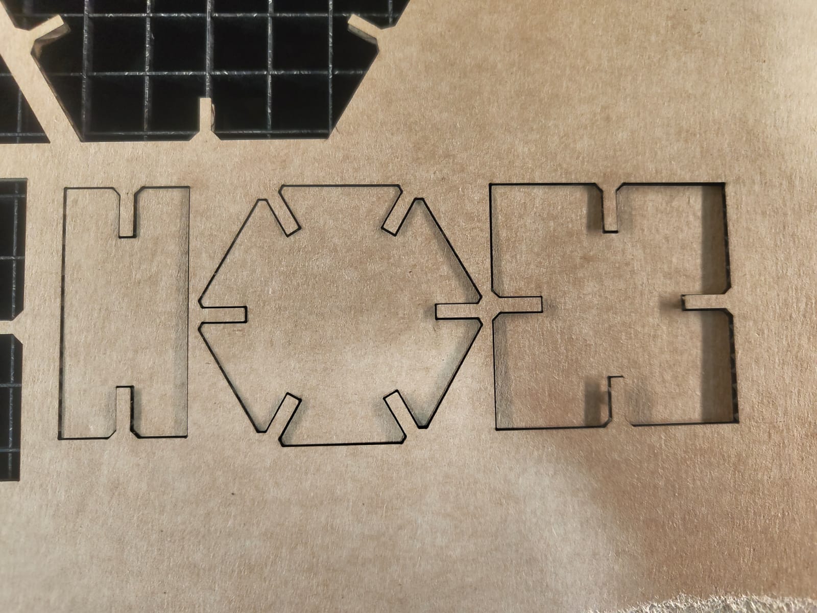
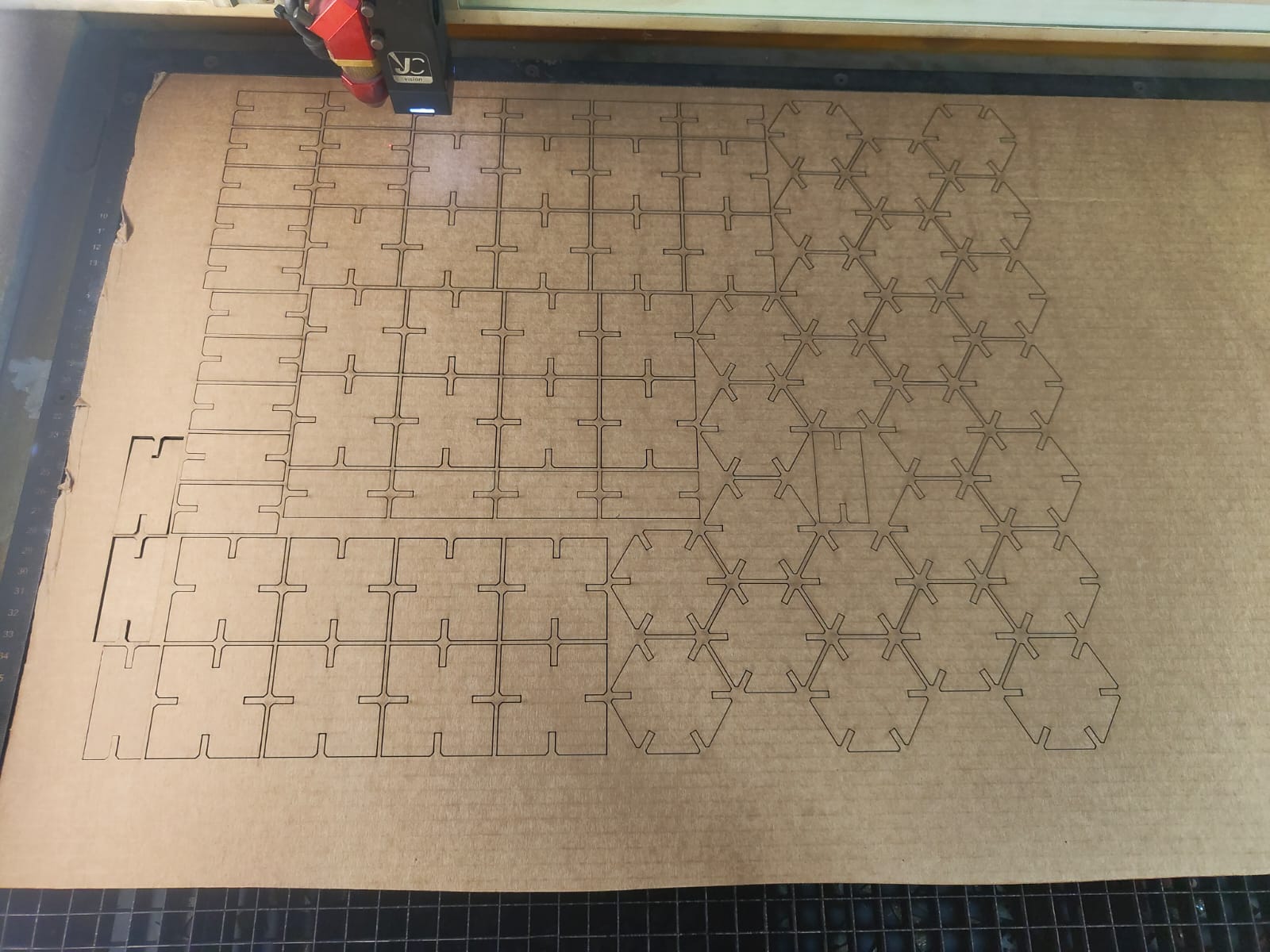
- Full pieces were cut in laser.
|
|
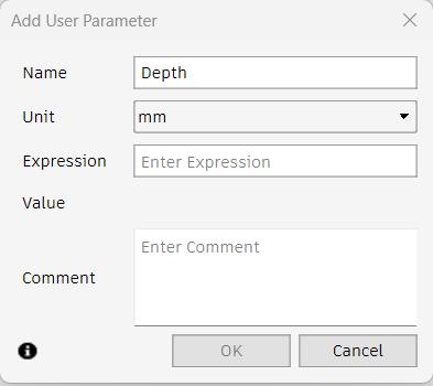
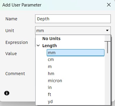
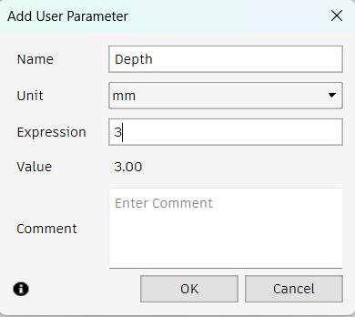
To add new parameter click the + icon and a new dialogue box appears. Initially set the name of the parameter. I named it as Depth. Then add the unit of the parameter. In my case it was in mm. Then specify the value of the parameter and click OK.
 |
 |
 |
 |
 |
 |
 |
 |
 |
 |
 |
 |
 |
Result
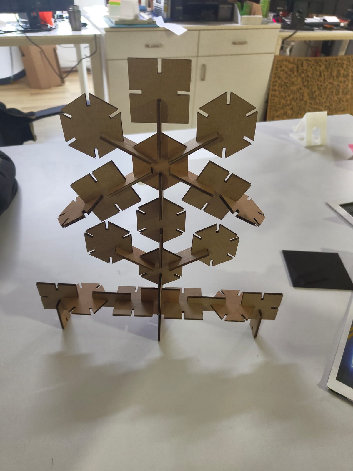
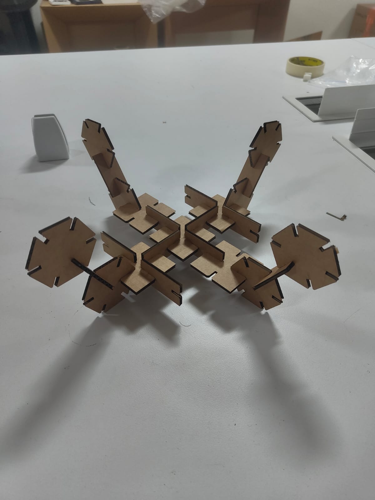
I assembled the shapes I cut to get this shapes.
 |
 |
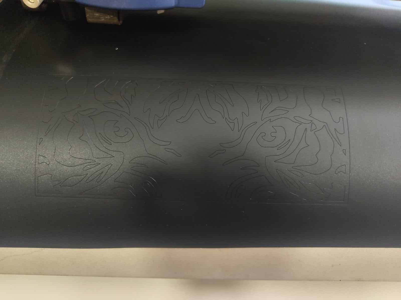
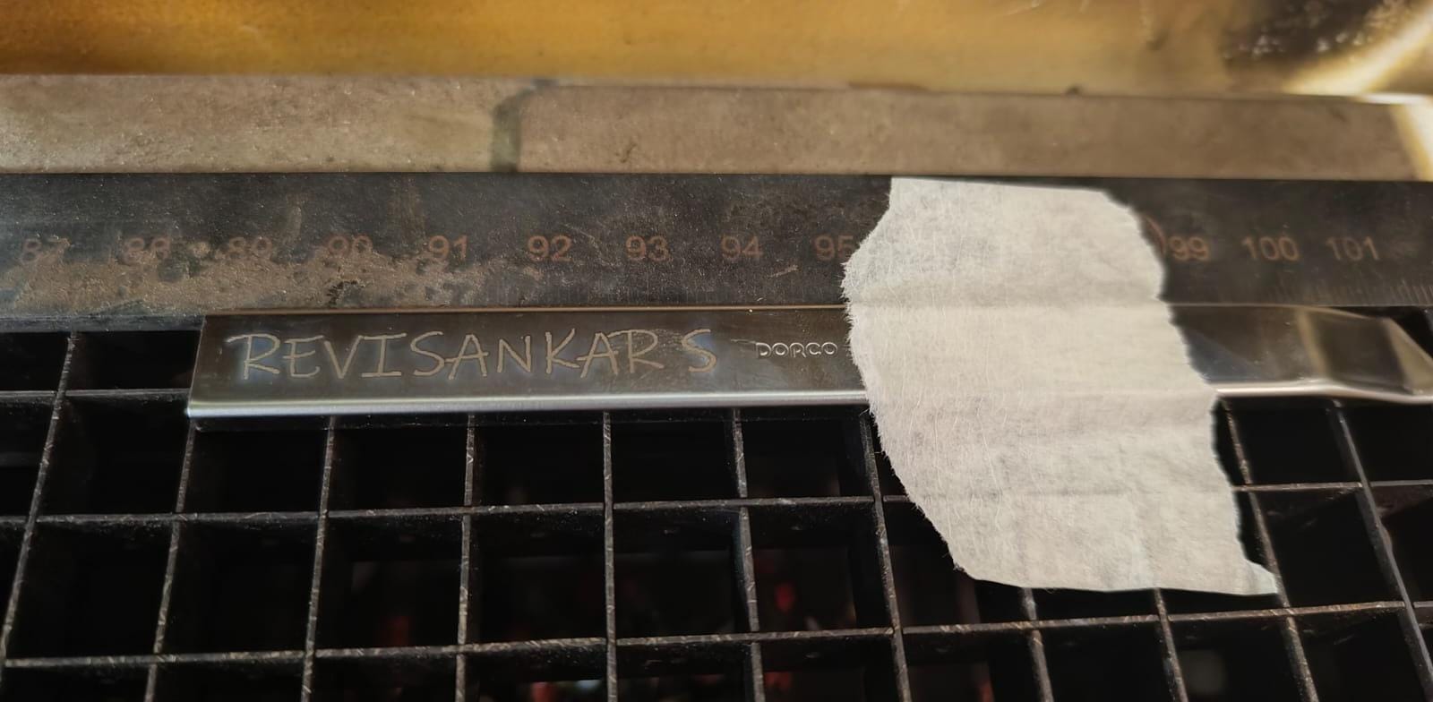
Metal Engraving
Since our Trotec Speedy 400 flexx laser cutter also has a fiber laser source, it can engrave metals as well. I tested this by engraving my name on a stainless steel knife.
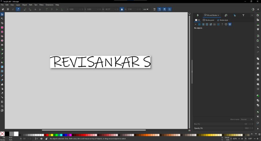
- I typed my name in Inkscape and resized it to fit the knife and sent the file to the Job Control Software.
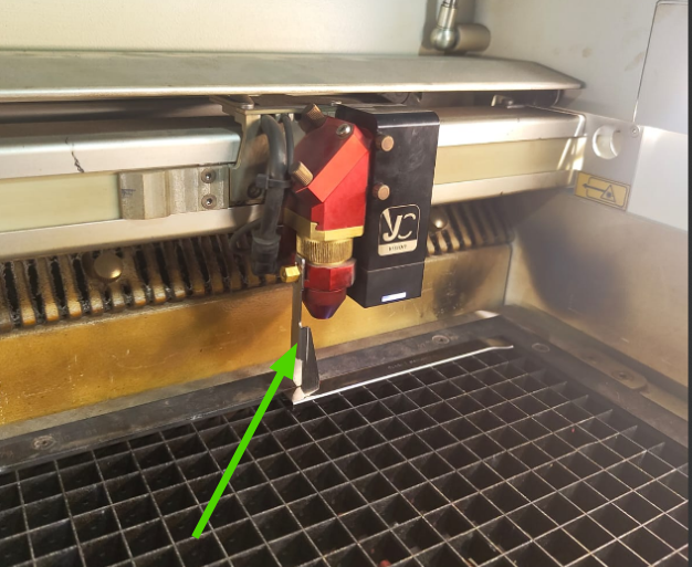
- As the area of the knife is so small I took the focus by the focus tool.
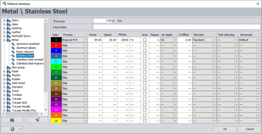
- With the following Parameters I got this result. As i discussed with my instructors about the parameters for the metal engraving they told me to increase the laser power and reduce the speed to engrave. Also they suggested a power of 90% and a speed of 20 and 1 pass. With these parameters I got the perfect result.
 |
 |
Hero Shot
|
|
Conclusion
This week, I learned about the laser cutter and its parameters, including kerf, power, feed, and pass for different materials. I explored the differences between engraving and cutting, designed a parametric model using values from our group project, and worked with the vinyl cutter to cut a design.