16. Wildcard Week
Objectives
- Individual Assignment: Design and produce something with a digital process (incorporating computer-aided design and manufacturing) not covered in another assignment, documenting the requirements that your assignment meets, and including everything necessary to reproduce it. Possibilities include (but are not limited to):
Individual Assignment: Making Molds using Vacuum forming
About Vacuum Forming
Vaccum forming, along with pressure forming, are the most common types of thermoplastic manufacturing processes, where a sheet of plastic is heated to make it pliable, shaped using a mould, and then cooled to harden it.

This article from Formlabs explains the process of vacuum forming as follows:
- A plastic sheet is clamped in place in an open frame
- The plastic sheet is then heated until it becomes pliable
- The pliable plastic sheet is brought down on a mold that is capable of handling the high temeperature. A vaccum is applied on the opposite side to pull the sheet to form a countour of the 3D shape
- Once the plastic cools, it is then released from the clamp and the mold. The excess is then trimmed out or sanded out depending on the requirement.
Using the Makyu FormBox
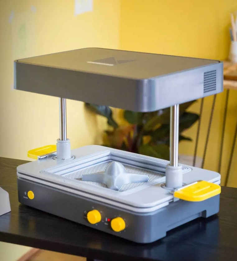
For this assignment, I will be using the Mayku FormBox, a desktop vaccum forming machine
The Makyu FormBox has the following specs and general information (extracted from their official website):
- Height: 466 mm (~18.35 in)
- Forming bed: 200mm × 200mm x 130mm (~7.9 x 7.9 x 5.1 inches) (L x W x H)
- Weight: 13kg (~28.7 pounds)
- 110 and 240V plug adapters available
- Heater range: 160-340°C (320-644°F)
- Compatible materials:
- for forming: PETg, HIPS, ABS, Polystyrene, Polypropylene, Polycarbonate, Polycarbonate, Polycarbonate
- for casting: Concrete, silicone, water, foram, chocolate, jesmonite, jello, plaster, resin
- Shipping: UK, EU, USA, and other select regions
Design Rules for 3D printed Molds
The main advantages of vaccumforming are affordability and quick turn around of time in minutes. However there are some design constraints that should be followed when designing a 3D printed mold
- Draft angle of 3-5º. Alternatively, add at least 1º of draft for every 2cm of height.
- Recommended to keep the number of shells/walls to 4
- Keep 25% infill when 3D printing
- Keep layer height minimum (~0.1 mm) to achieve smooth finish. Additionlly post processing will be required to get the best possible finish
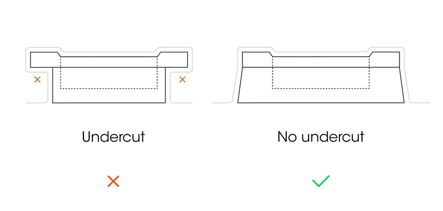
- Avoid undercuts. This can be mitigated by adding draft to vertical walls or other similar surfaces.
- Avoid sharp angles (>90º). Instead use fillets (~2mm) to help easier release from the mold
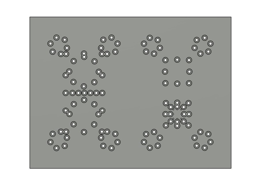
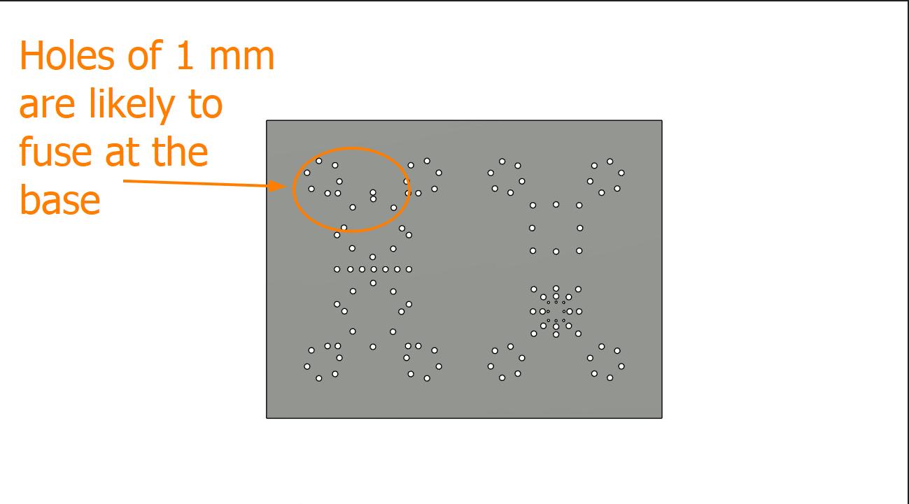
- If your design has pockets or other cavities where air can get trapped between the plastic sheet and the mold, you need to add air holes (~1-2mm) to allow for maximum suction, whcih results in the sheet capturing better details. On testing I found out that 2 mm prevents heated filament from deforming and closing the hole.
- Wide parts are easier to vaccum form than taller parts, so always try to orient the longest dimension horizontally in parallel with the base
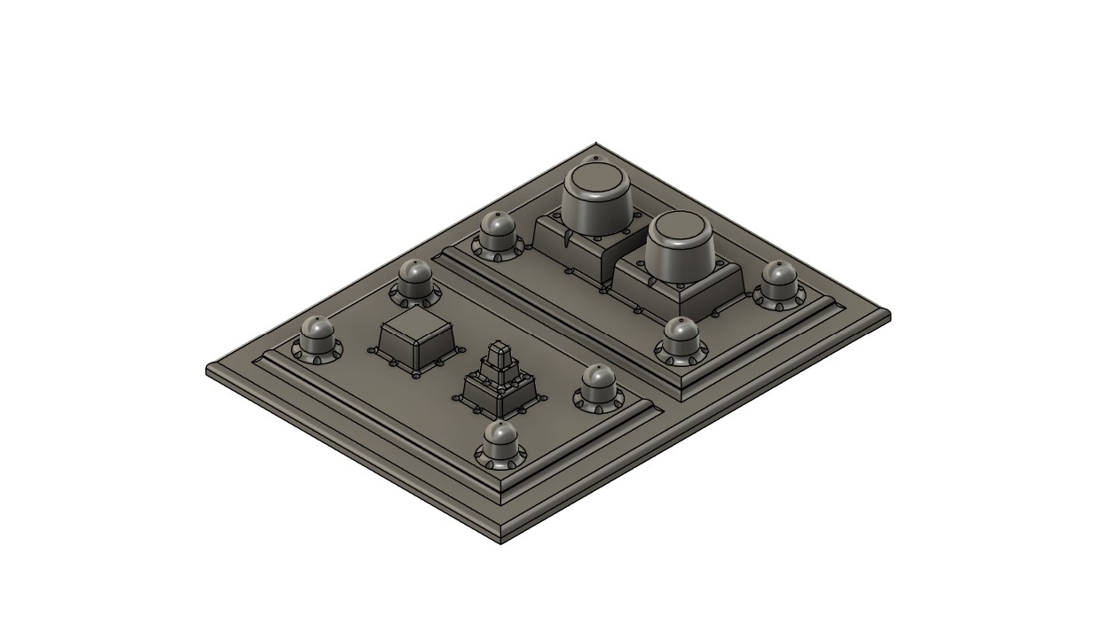
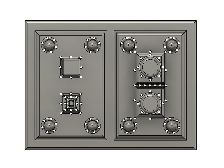
Designing a 2 Part Mold
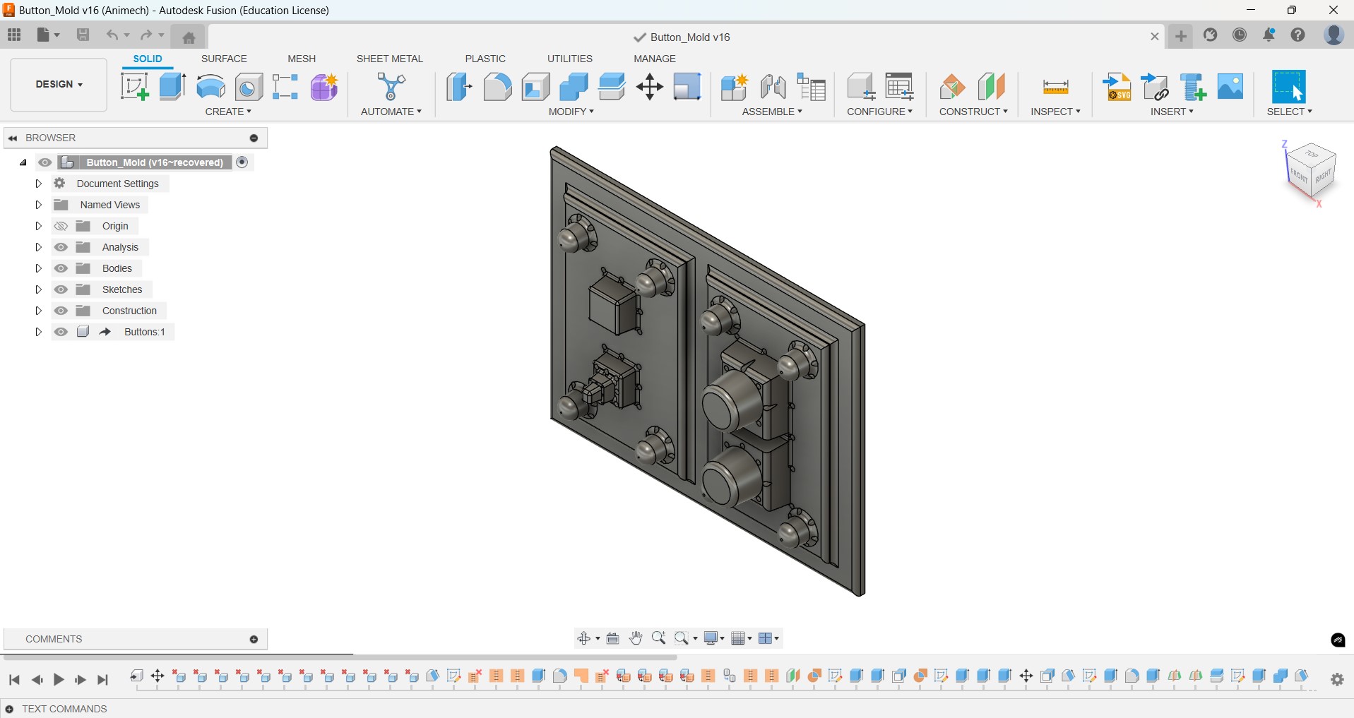
I wanted to make a mold for casting silicone buttons that I will be using in my final project. I followed all the above set design rules to the best of my capabilty while designing in Fusion to make sure I get the best possible results.
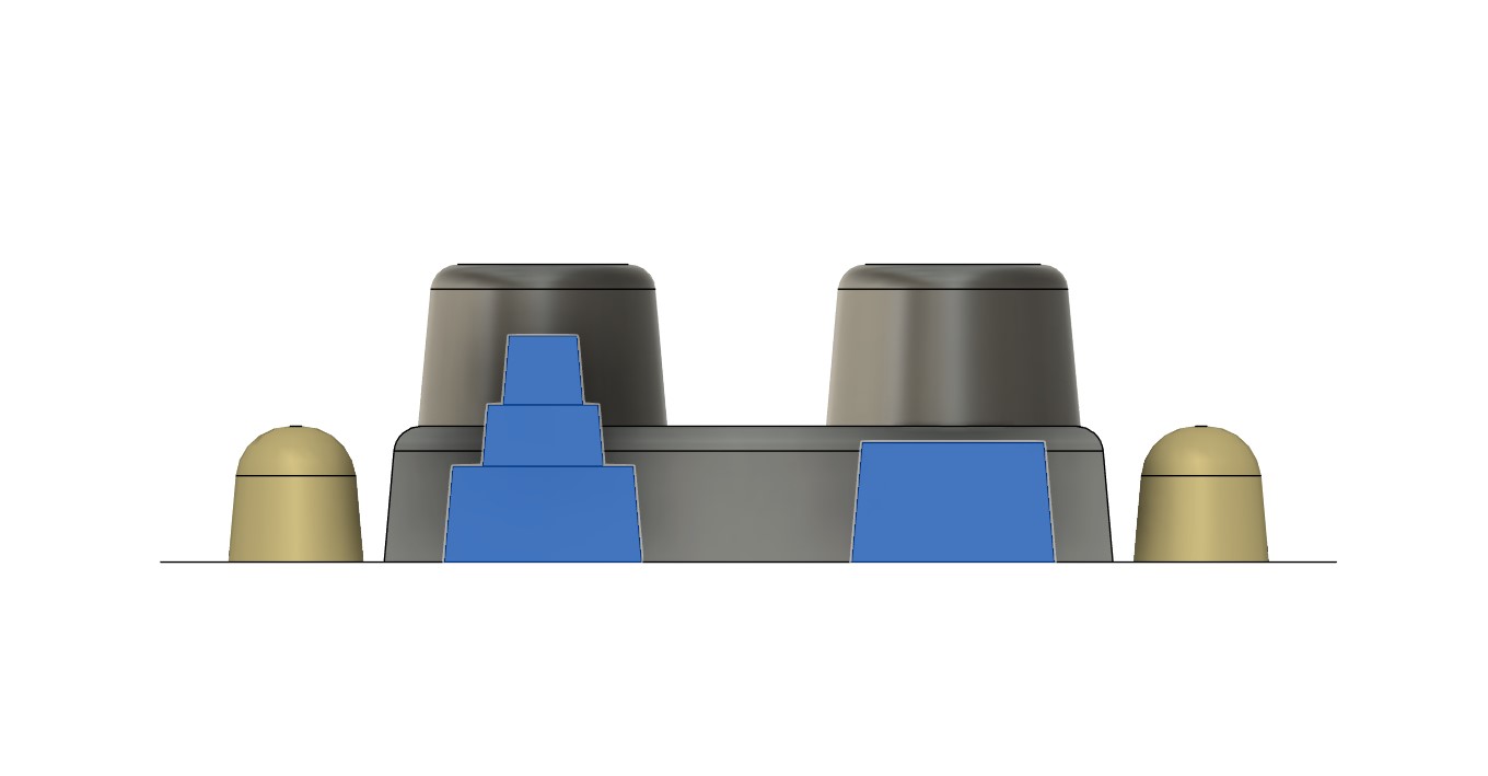
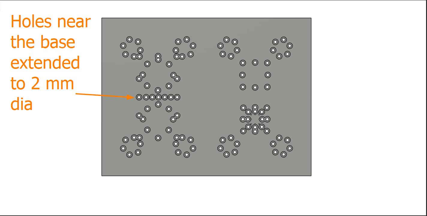
After some design revisions, I extended the holes through the base by 1 mm, total 2mm diameter so that the filament at the base don't fuse together
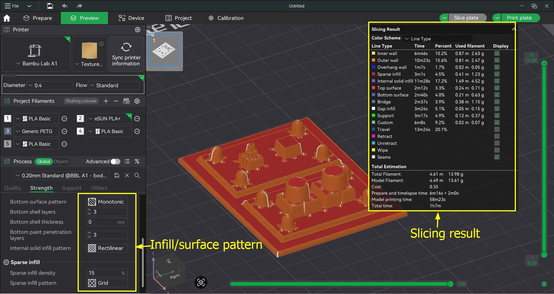
These are the slicing settings I used.
 I printed this mold in eSUN PLA+
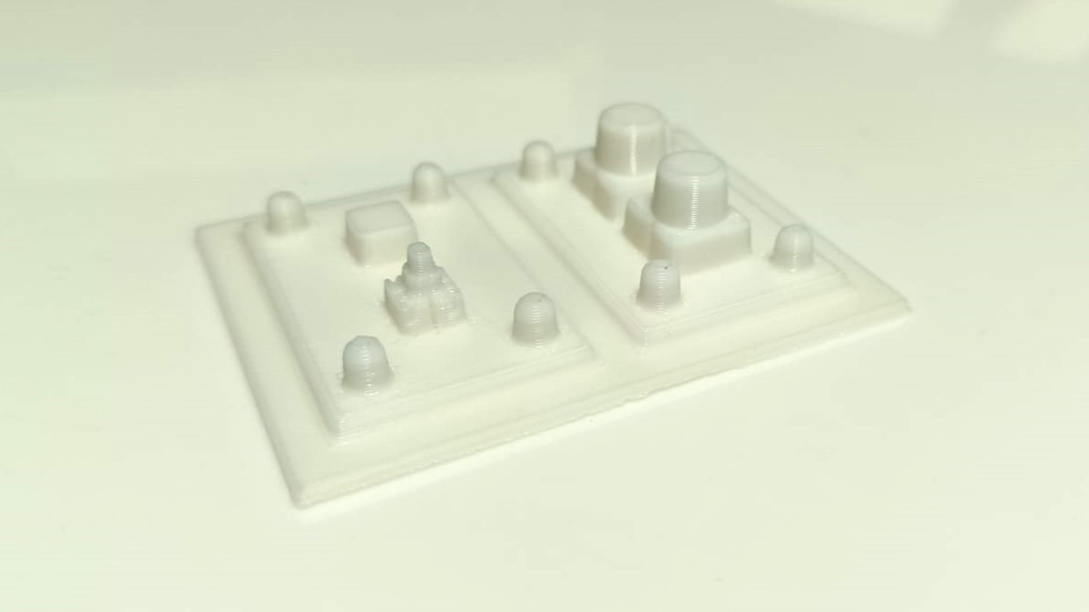
Depending on the application, additional post processing will be required
Vacuum Forming
We will be using Mayku Clear Sheet for our purpose. It is transparent, food-safe and made from recycled plastic. I was not able to find documentation on the exact material composition of the clear sheet, but I believe it is most likely PETG.
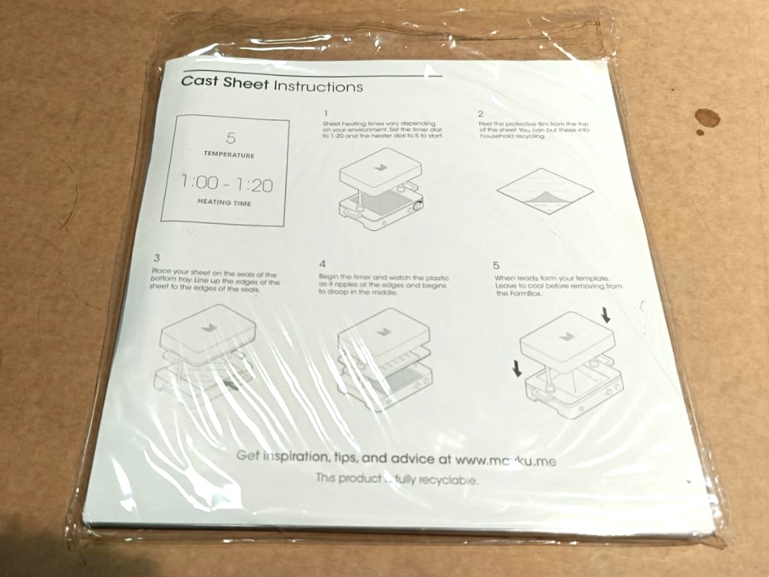
The instruction manual tells us the operating conditions for each sheet we purchase from Maku, including the Clear Sheet.
Using the Vaccuum Former is a simple task that takes 5 to 10 minutes from start to finish. The steps are as follows:
- First we need to plug the FormBox to power socket.
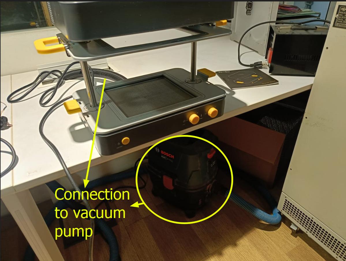
- Then, we need to plug the vaccum cleaner into the back of the Formbox and switch it ON.
- Connect the vaccum cleaner's hose into the vacuum tube of the FormBox.
- Switch the FormBox ON
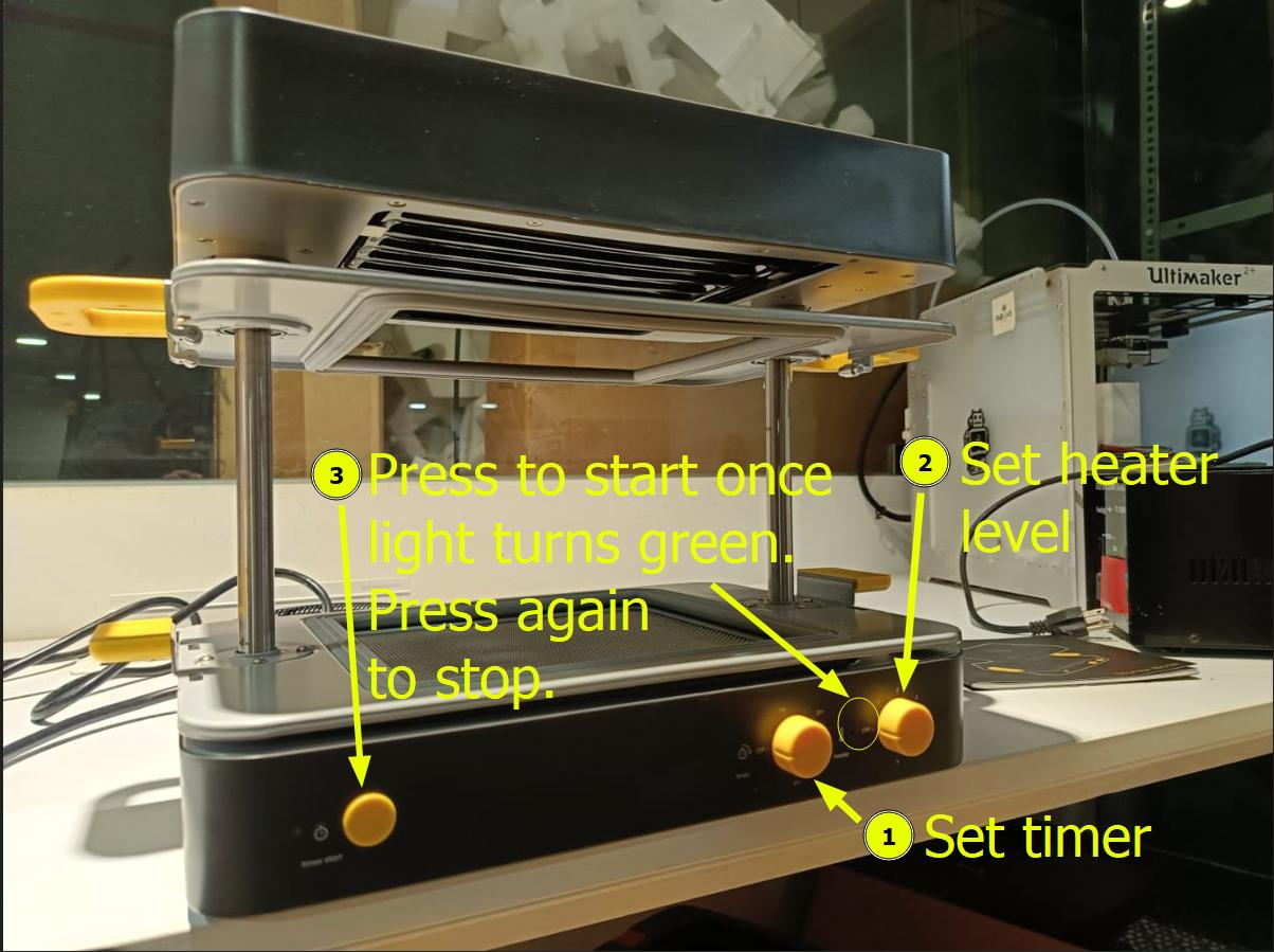
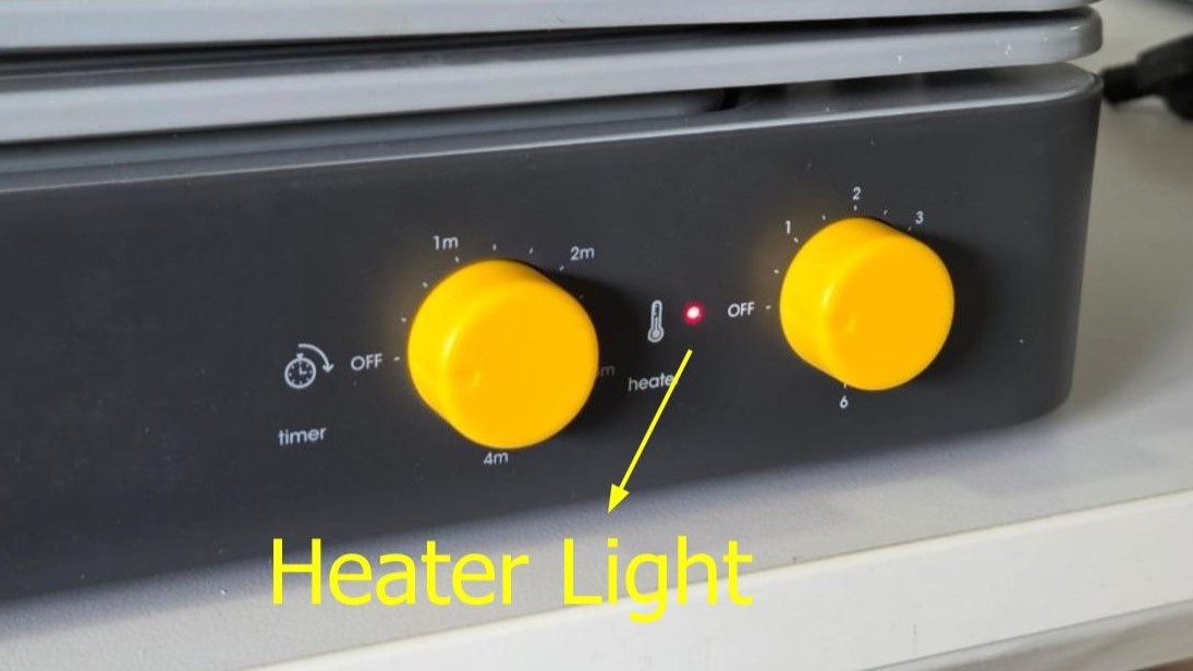
- Now set the timer dial to recommended time (1:20 in this case)
- Now, we set the heater dial to recommened heating level (5 in this case). The heater light will flash orange, indicating that it is preheating
- Now wait until the heater light turns green; this means that preheating has been completed.
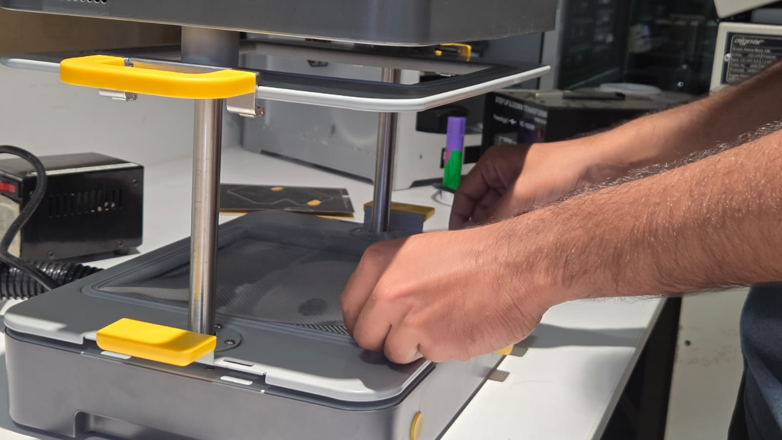
- Unclamp the tray handles, and bring the top tray to the top
- Peel the protective film and place it on the bottom tray, lining up the edges of the sheet with the edges of the seals
- Lower the top tray onto the bottom tray. Clamp the tray handles to lock the sheet in place in between the top and bottom trays
- Now raise the trays upwards in the direction of the heater until they snap into place at the top
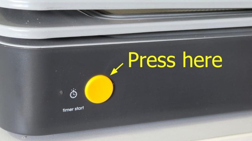
- Press the timer start button. The heater light will flash orange, you will hear a ticking sound
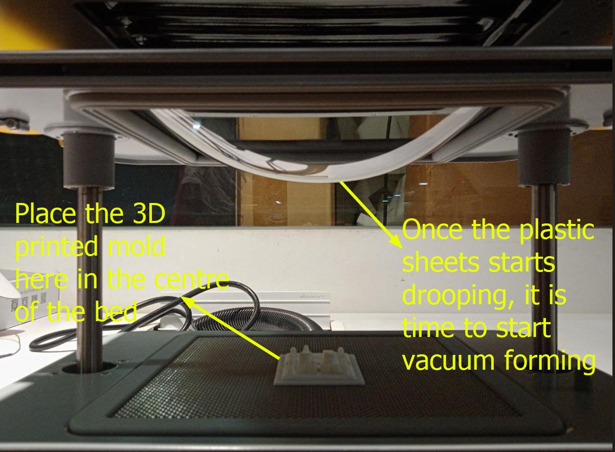
- Once the bell starts ringing at a more intense pace and the plastic sheet starts deforming, it is time to start the vacuforming process
- Place the mold onto the center of the FormBox base
- Bring both trays along with clear sheet down onto the 3D printed mold. A vacuum form will start once the sheet reaches near the bottom
- Once completely formed, leeave 1-2 minutes for the sheet to cool
- Once cooled, unclamp the tray handles and open the tray to release the mold and the formed sheet
Post Processing
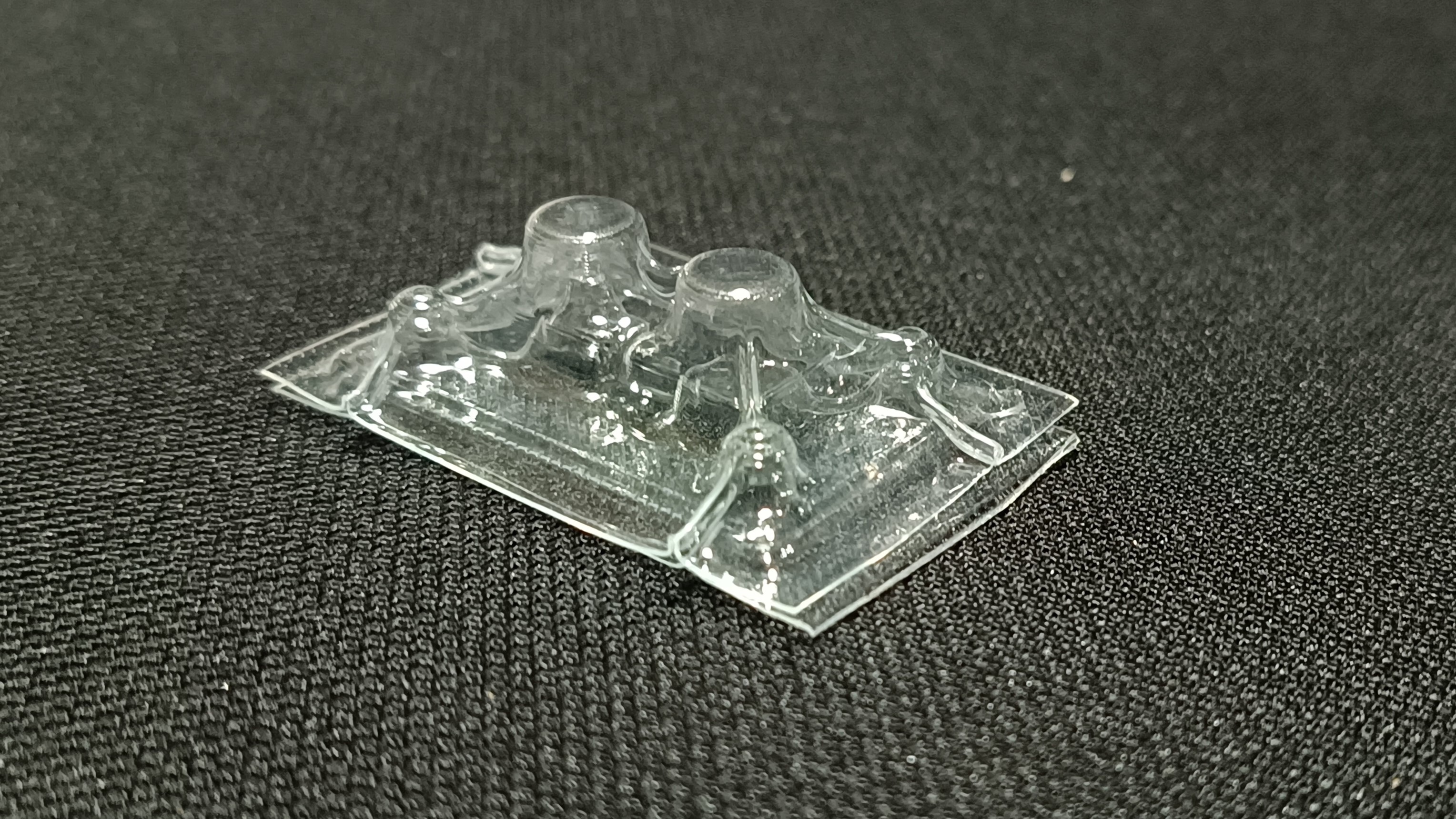
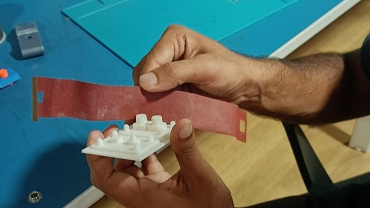
After some cutting using scissors, this is what I got finally
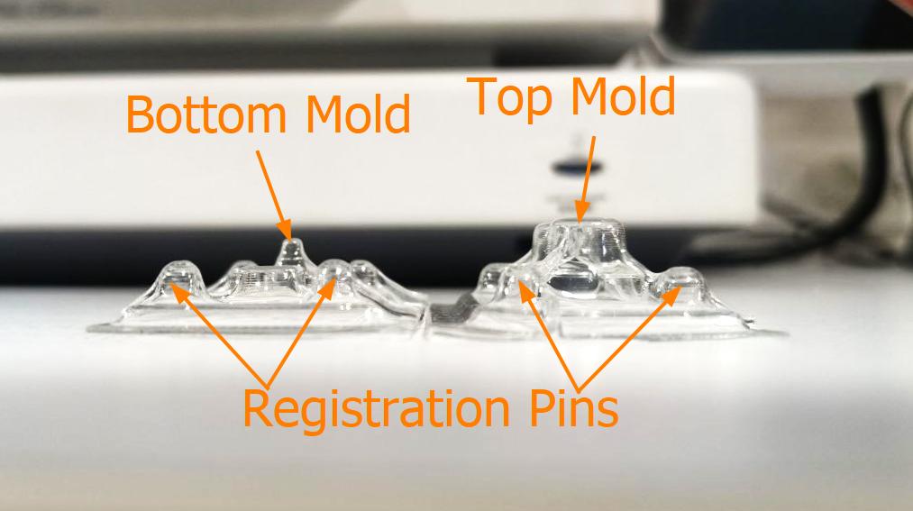
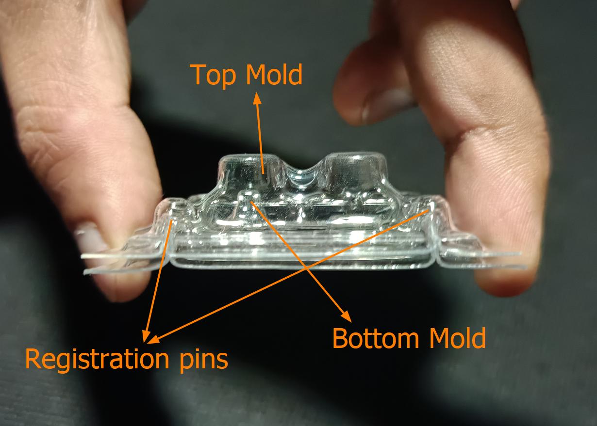
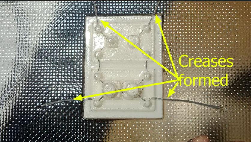
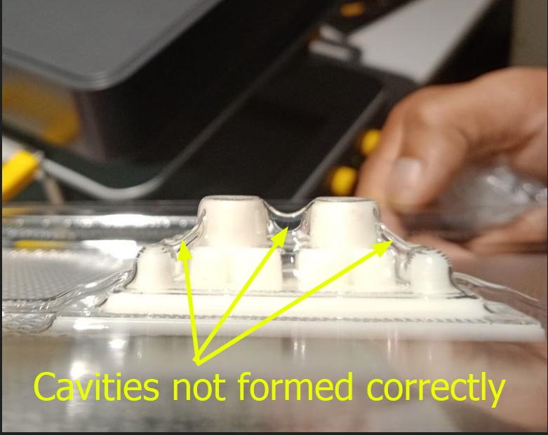
As you can see from the images seen above, this mold is a failure due to the following reasons:
- Formation of crease at the corners of the molds
- The air holes were not as effective at removing air as hoped, resulting in air gaps formed at multiple places in the mold
- The registration marks/lips did not fit inside the other as hoped, so it was not possible to lock the two molds in place like planned
Conclusion
As part of Wild Card Week, I set out to explore the use of vacuum forming to make 2 part molds. compared to 3D printing and wax machining, vacuum forming is the fastest and the easiest to make molds. However they will have inaccuracies due to the manufacturing process, so these molds can only be used for low-precision parts. Additionally, there are a lot of design constraints that go into designing a 3D printed mold for vaccuum forming, which I explored this week.
Notes for the Future
- Fillet radius of both parts of the mold should not be of same radius: But making it so was too time-consuming, so I opted for using the same flllet radius and testing it out.
- Design Error: I am using two different kinds of switches with very different travel distances. Hence I actually needed two the silicon buttons to be seperate and not connected to a single piece. I made some slight adjustments to the design to make this possible, but as a result the distance between the two button 'positives' is very small once draft angle has been applied. If I were to try this technique once more, I would design the mold from scracth, accounting for this detail.
- Designing air holes:
- Air holes should be added after all the operations, included adding fillets are done to avoid geometry conflicts.
- Also, they need to be at least 2 mm at the base to prevent the filament at the base in contact with the hot bed from fusing and closing the holes above it.
- The air holes were not as effective at removing air as hoped, resulting in air gaps formed at multiple places in the mold
- Formation of creases at the corners of the molds: It must be checked why the creases are formed
- Registration Marks: The registration marks/lips did not fit inside the other as hoped, so it was not possible to lock the two molds in place like planned
References
References to help reader understand in detail
Look at previous year documentation