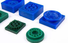
13. Molding & Casting
Objectives
- Group Assignment
- review the safety data sheets for each of your molding and casting materials, then make and compare test casts with each of them
- compare mold making processes
- Individual Assignment
- design a mold around the process you'll be using, produce it with a smooth surface finish that does not show the production process toolpath, and use it to cast parts
- extra credit: use more then two mold parts
Group Assignment
Click here to access the group assignment.
Individual Assignment
Designing an Eyeball
I was impressed by this instructable on making realistic resin eyes using 3D printed parts, so I wanted to adapted the author's process to fit the requirements of this week.
I designed a simple eyeball using Fusion mostly using spheres. A cavity was made in the eyeball for the iris. The hollow cylinder at the center represented the pupil. The pupil and the iris would be painted before I apply clear resin on top to fill the cavity.
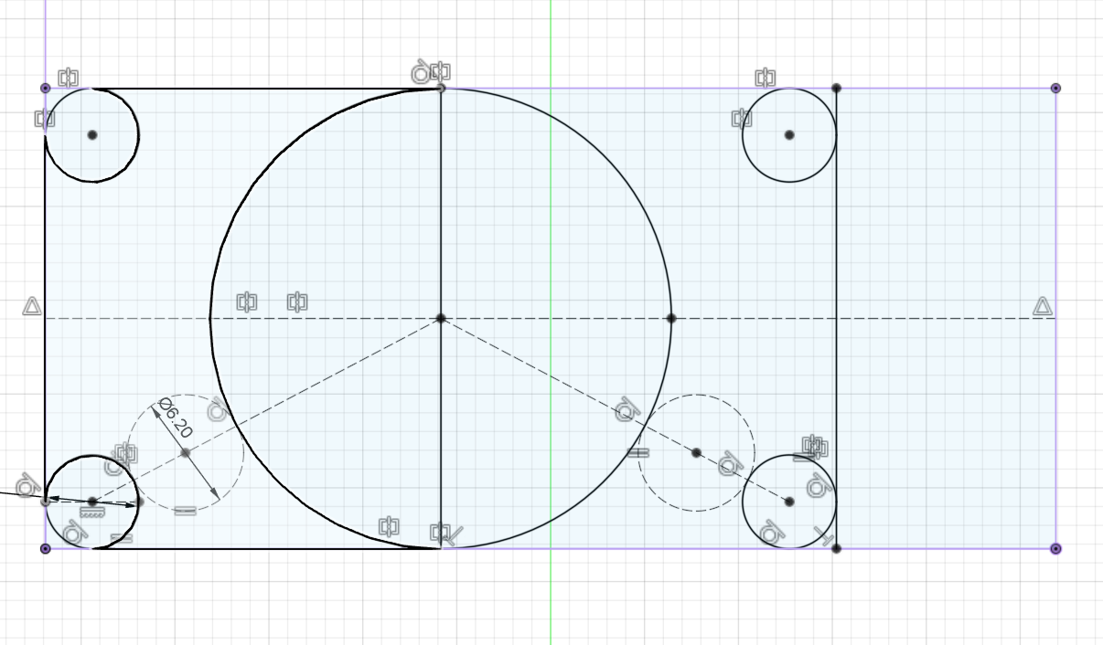
Designing the Positive Mold
First we have to design a 'positive' mold of the 3D model that will be machined on wax, which will in turn be used to create the 'negative' mold using silicone, which will be used to create multiple copies of the eyeball
Draft angles of 1 degree have been added to the walls of the mold and 2 degrees have been added to the registration marks.
I have tried my best to provide at least 6 mm space to allow the large bit reach and remove most of the material in an effort to reduce machining time.
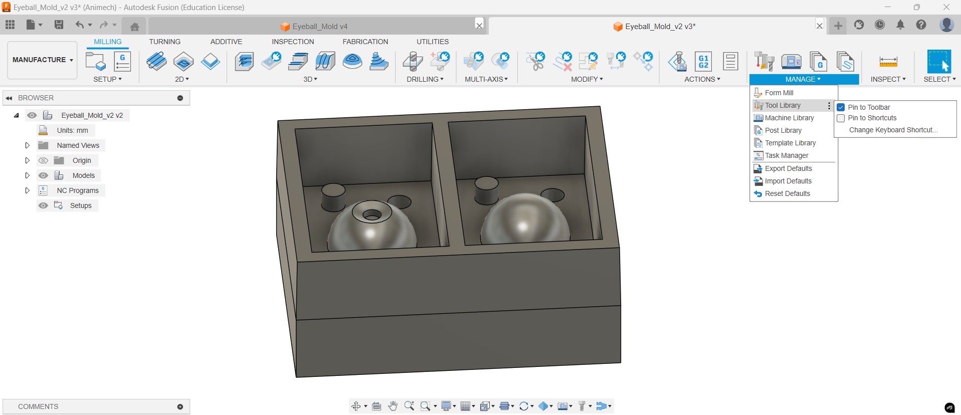
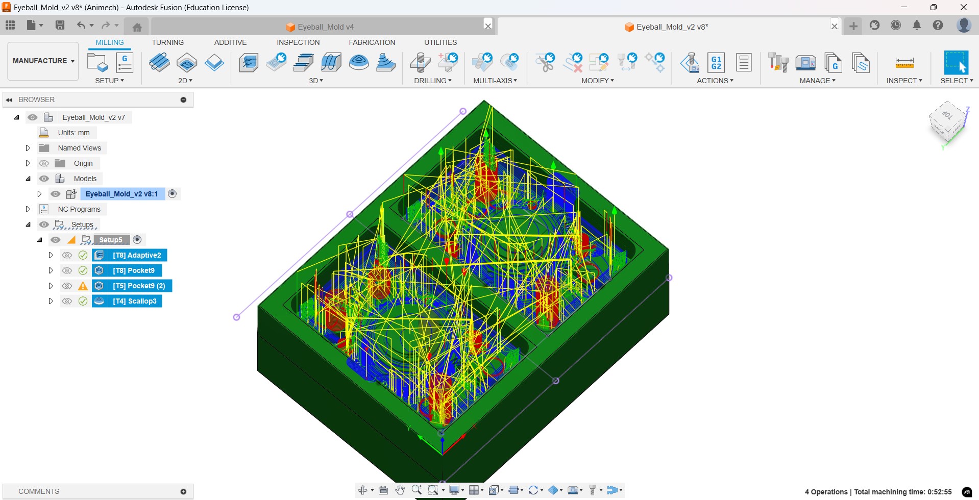
Computer Aided Manufacturing (CAM) in Fusion
Now we will use the CAM tools inside Fusion to generate the toolpath we want.
To use CAM, we go to Manufacture Workspace. I added the tool library from
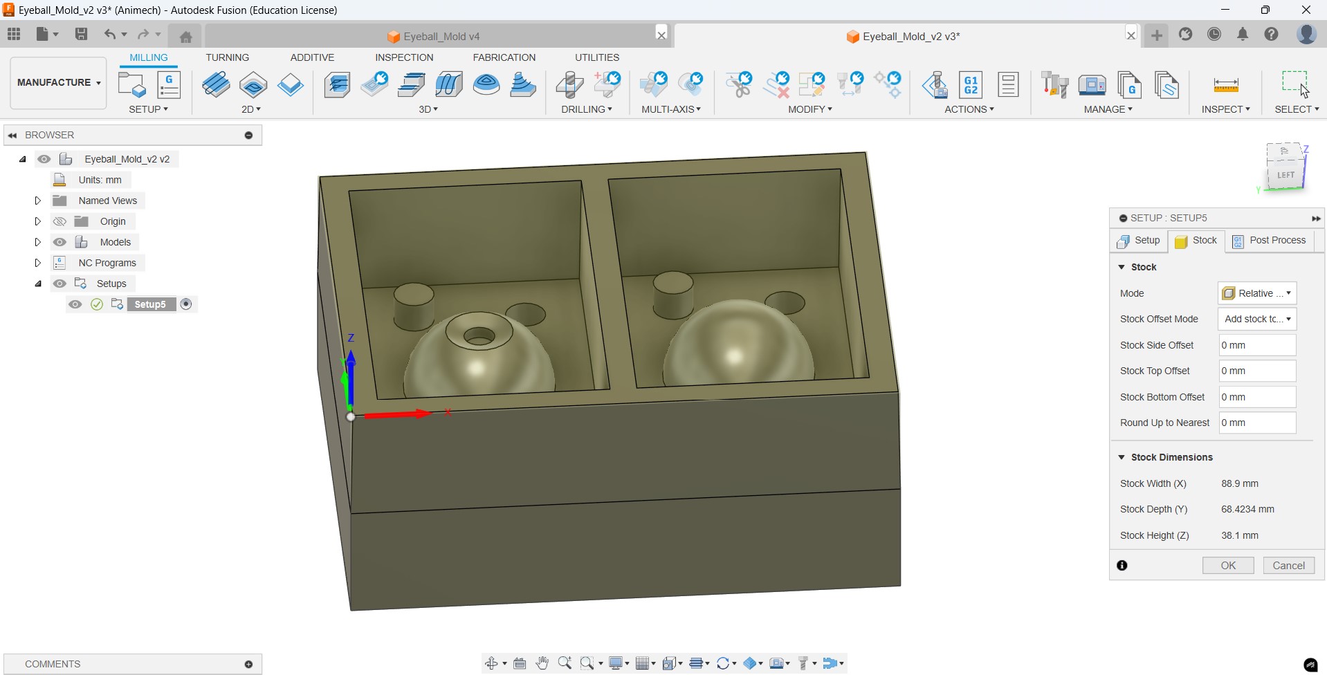
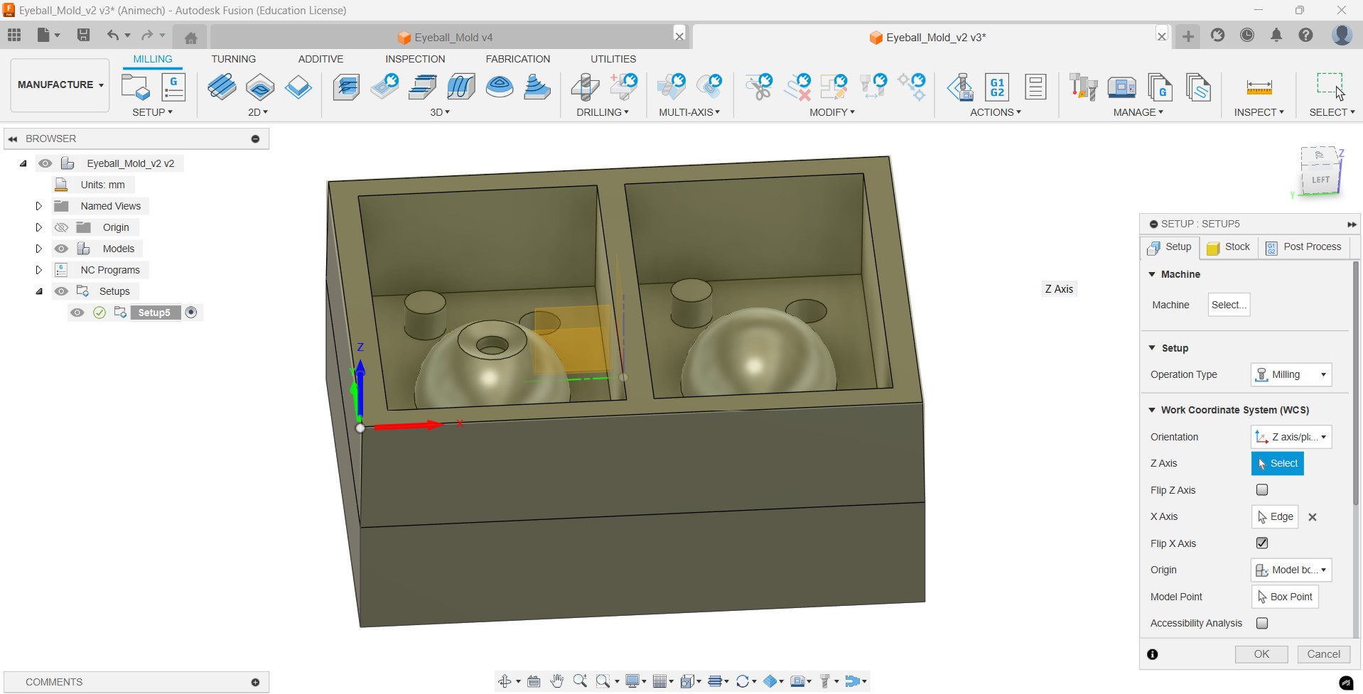
Then we go to Setup and set the work dimensions and the XYZ cordinates
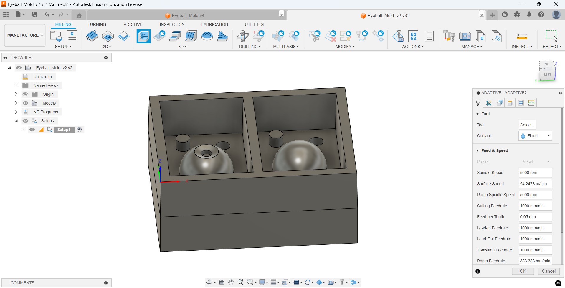
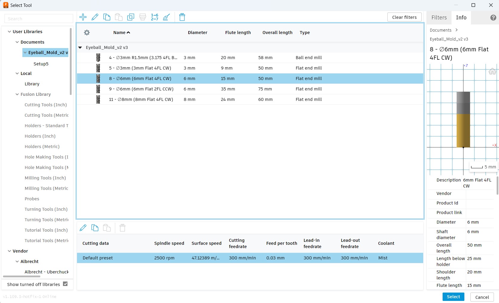
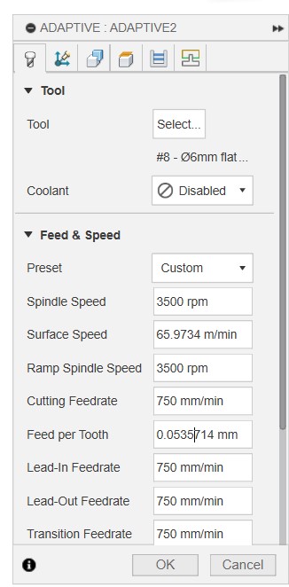
Then we set a tool operation (Adaptive clearing in my case), set the tool (6 mm 4 flute clock wise in my case), set the coolant to 'Disabled' and set the speed & feed rates that were selected based on previous experience by the instructors for the machine we are going to use
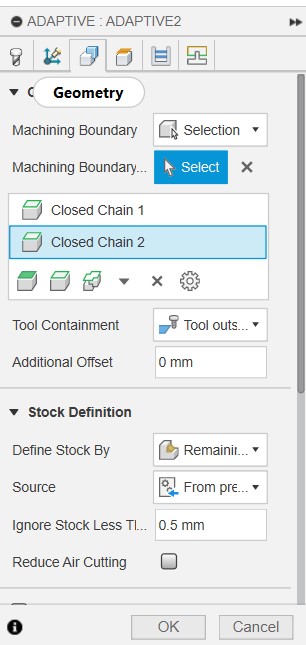
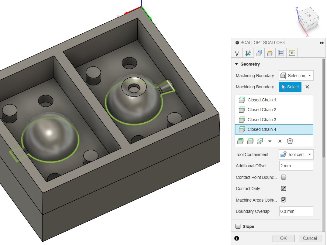
Then we adjust some parameters in Geometry; 'machining boundary' to 'selection', 'tool containment' to 'tool inside boundary' and 'ignore stock less than' to '0.5 mm', select the inner rectangles.
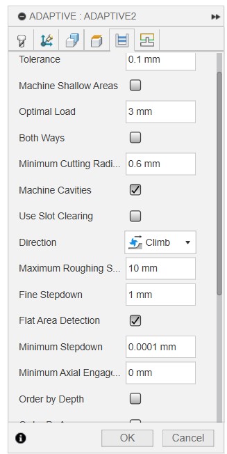
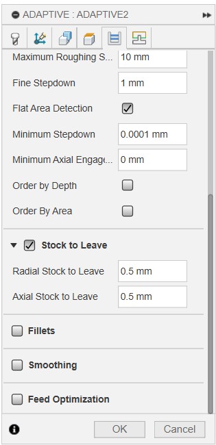
Then we go to Passes and set the optimal load to 50% (ie., 3mm for 6 mm bit), 'Maximum Roughing Stepdown' to 10 mm and Stock to Leave to 0.5 mm if not already set.
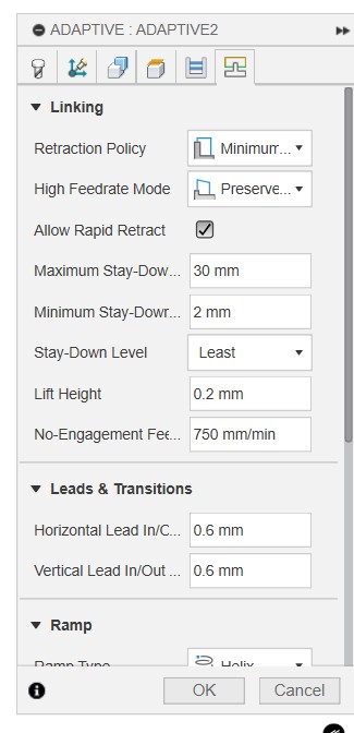
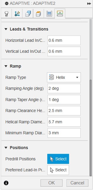
Then go to Linking, adjust retraction to minimum, amd make sure Ramp type is set to Helix, and a Ramp angle of 2 degree
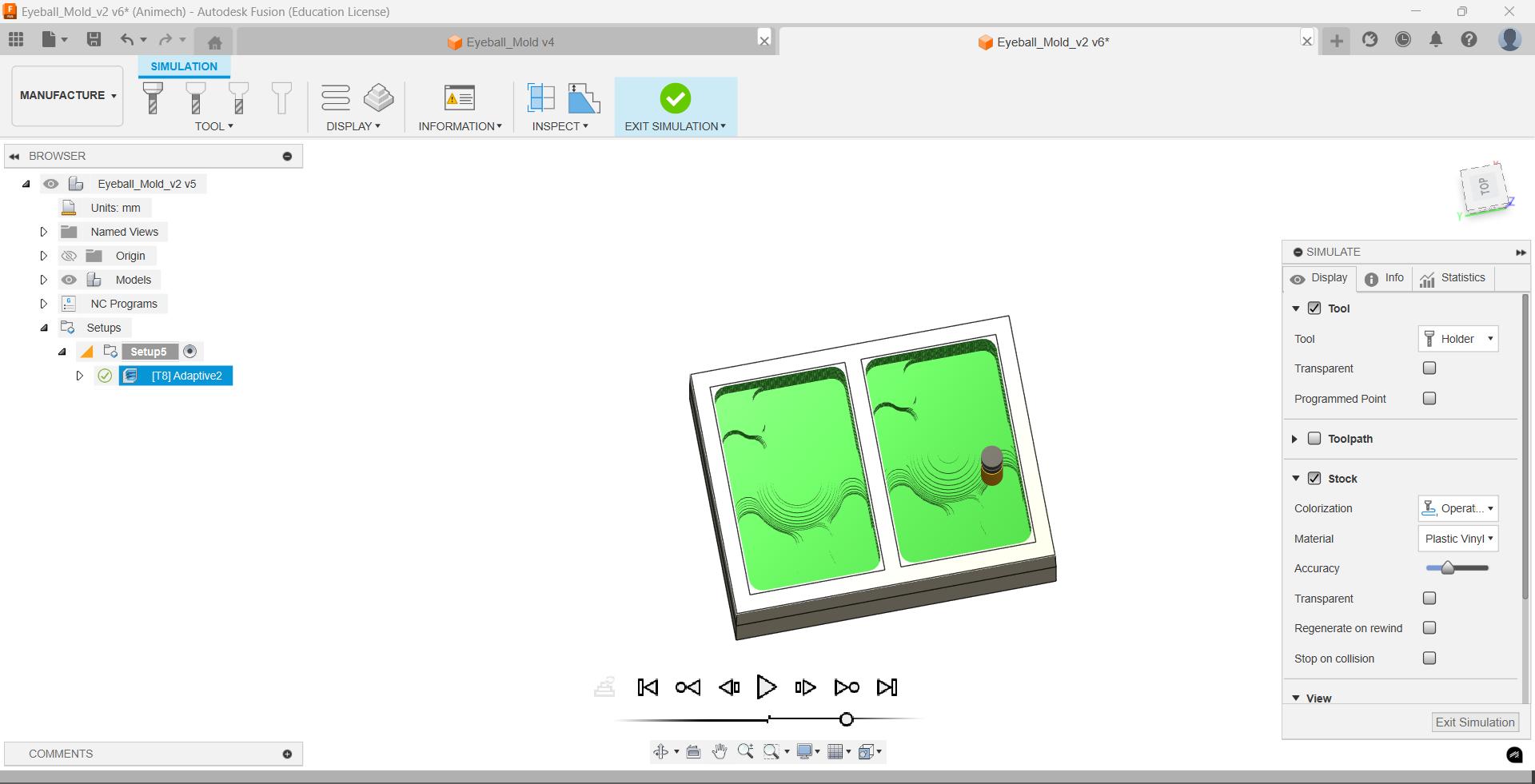
Then I generate the toolpath using Ctrl+G, and simulate to see the result.
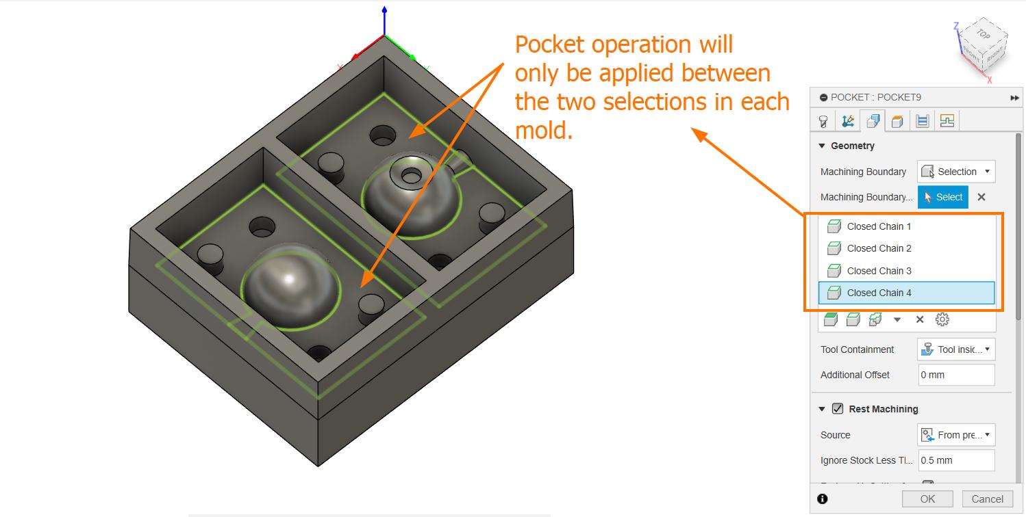
Then I added new Pocket operation using the same bit to clear the holes for the registratin marks, I set Ignore Stock to 0
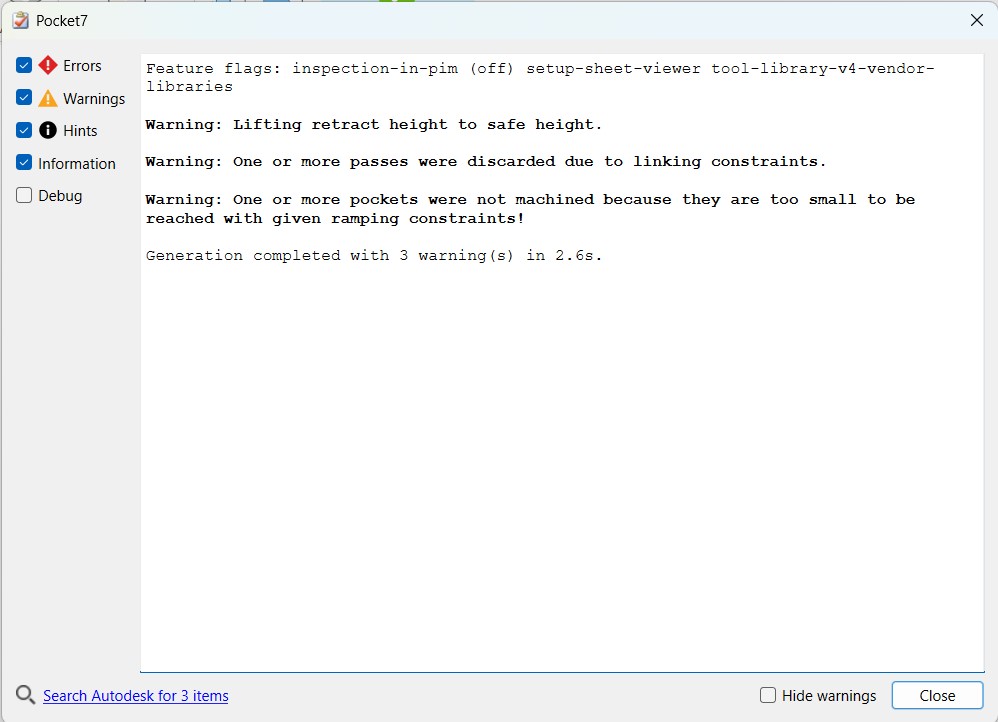
Error while trying to do Pocket operation. See Mistakes & solutions to see how the error was solved
Like this I completed all the CAM operations
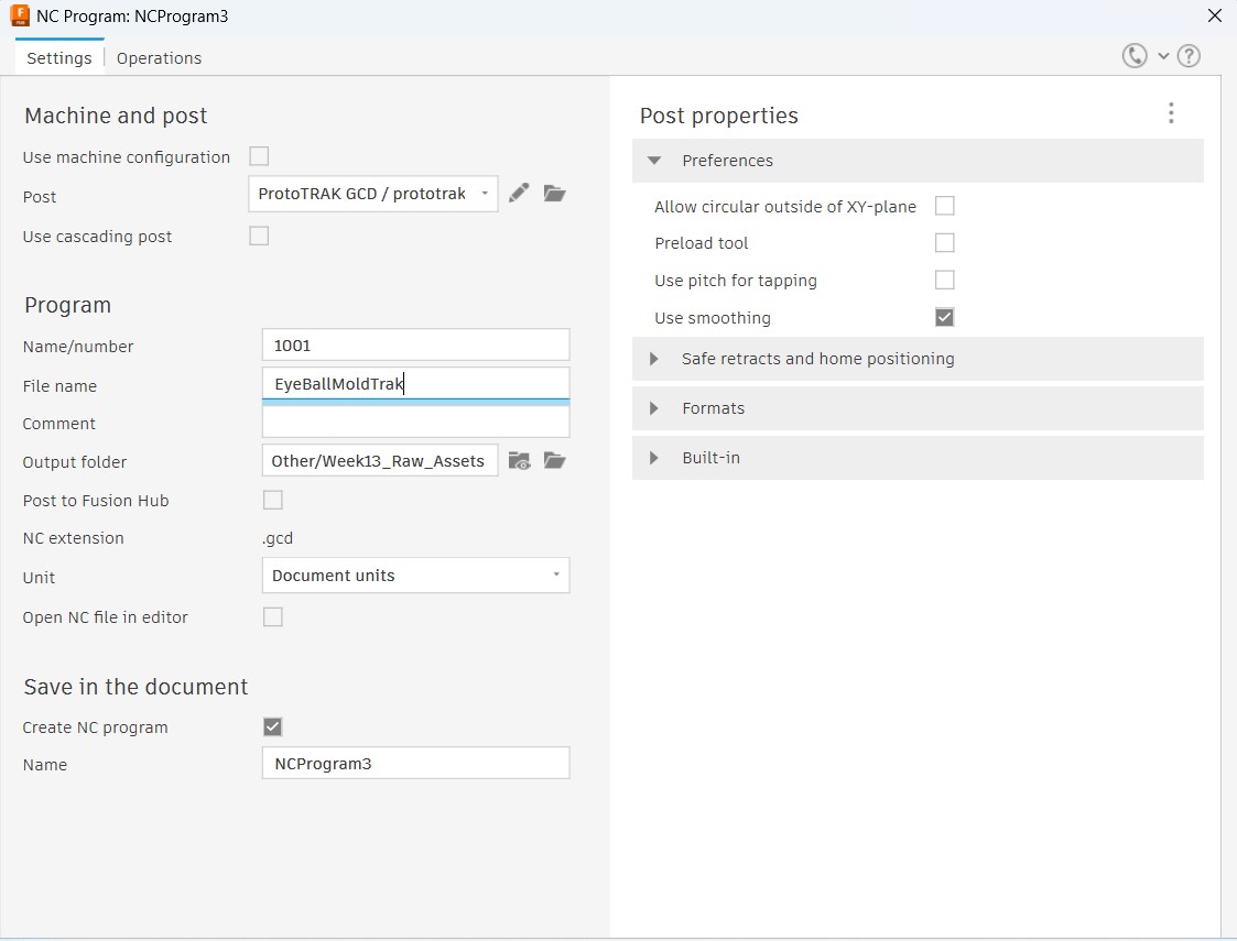
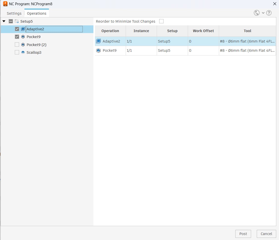
Then I go to Actions > Post Process and export as .gcd file. I can club multiple processes if they use the same bit
Machining the 'Positive' Mold
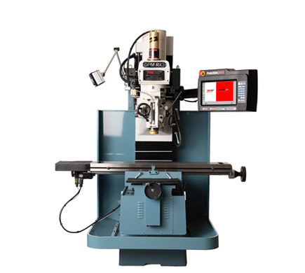
The positive mold will be milled out of Machining Wax. We will be ising the ProtoTrak CNC milling machine for our purpose
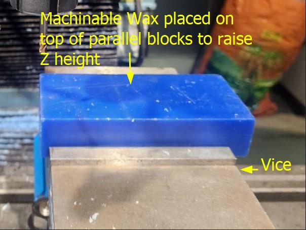
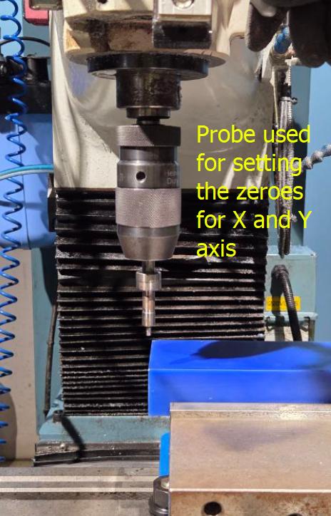
First step is to place the wax block into the vice, making sure that it is aligned parallel to the work surface. Then we set absolute zeros of X and Y using the probe
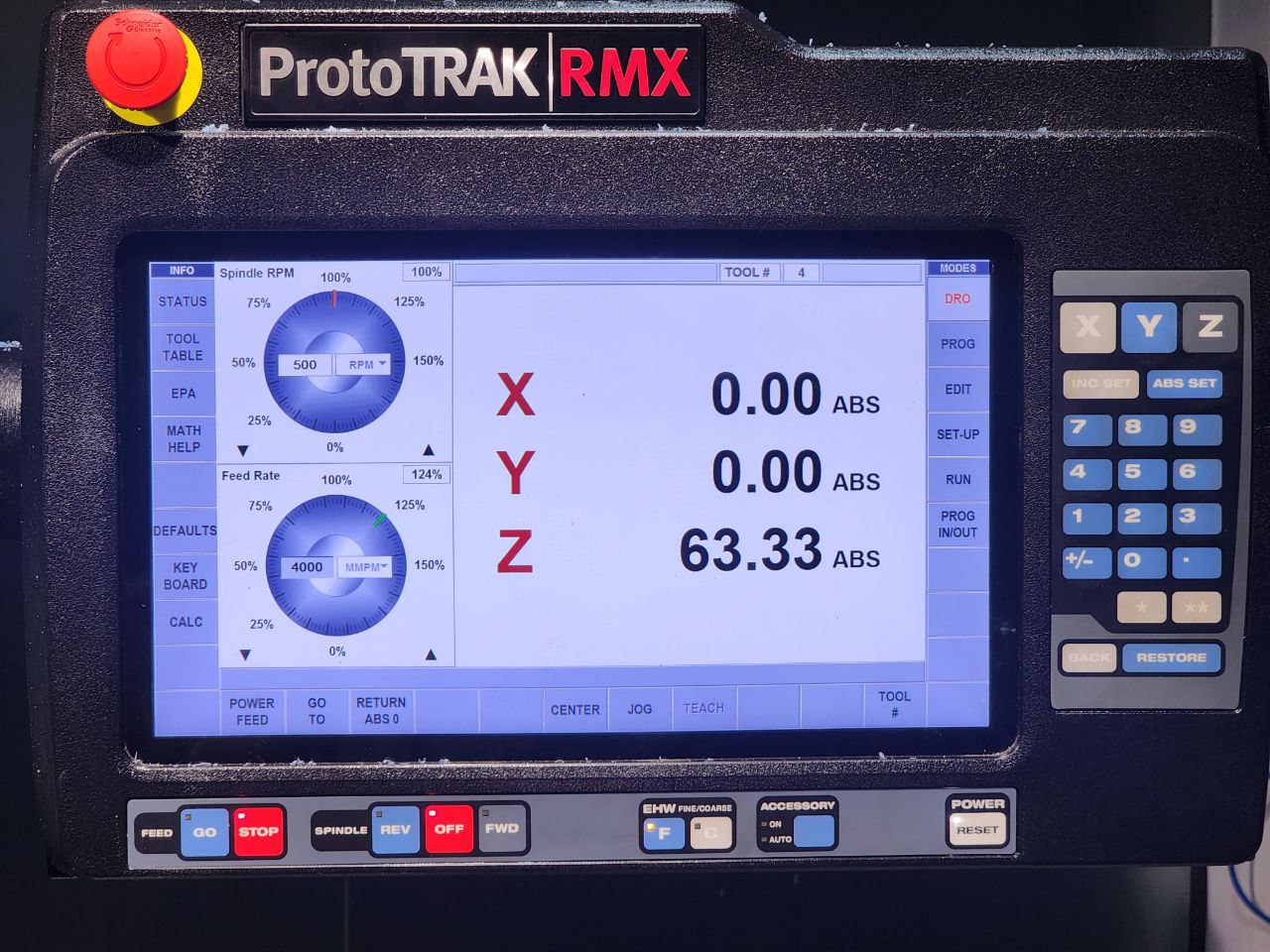
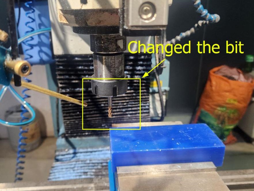
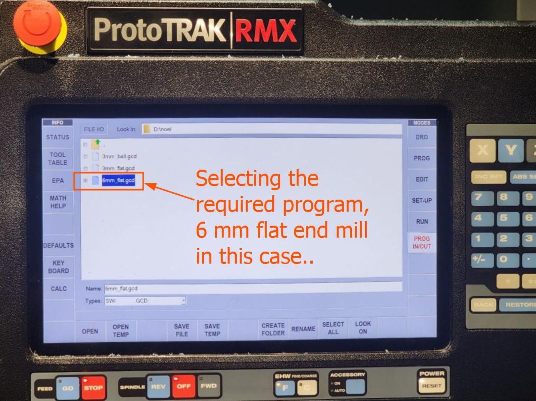
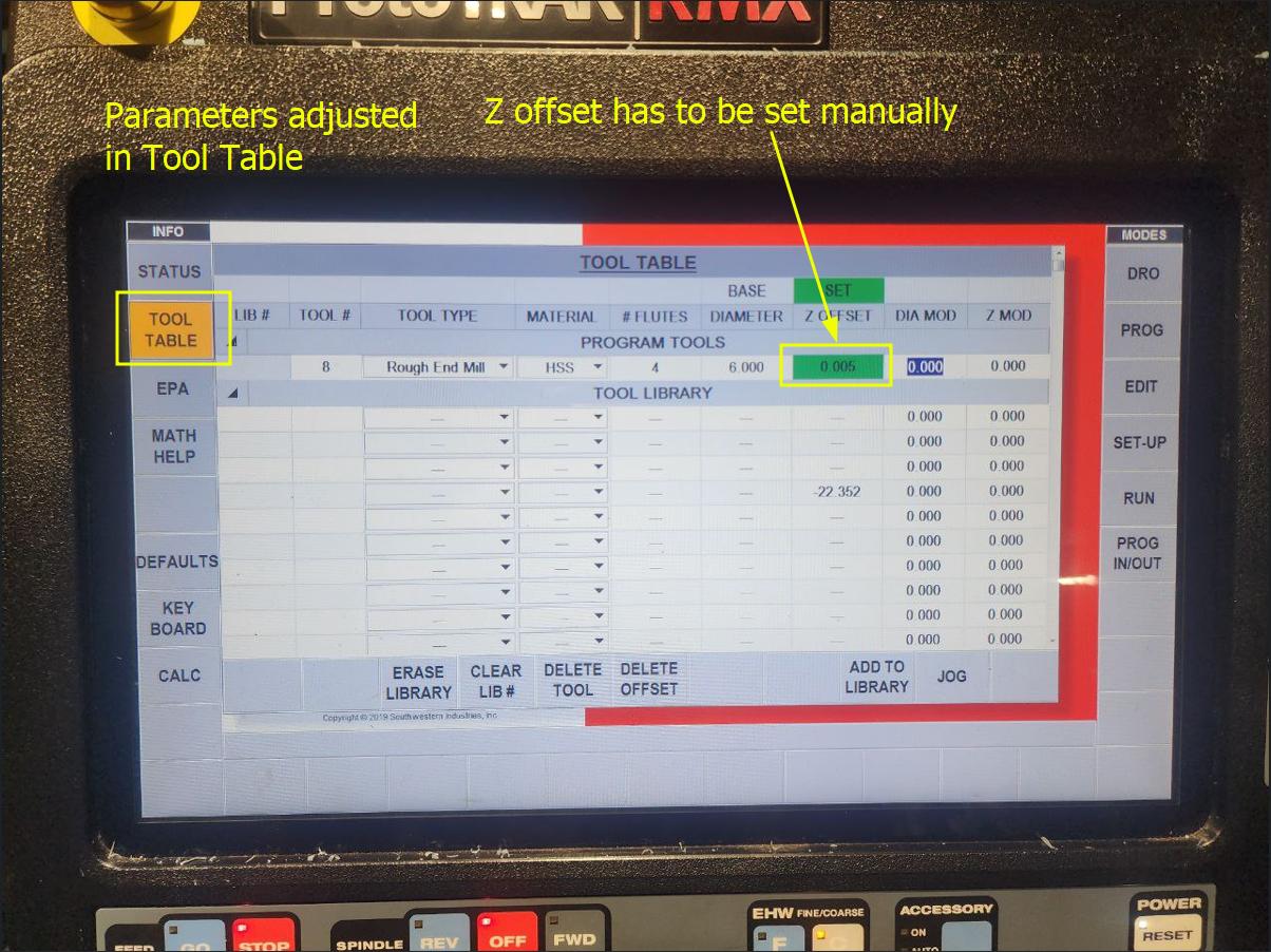
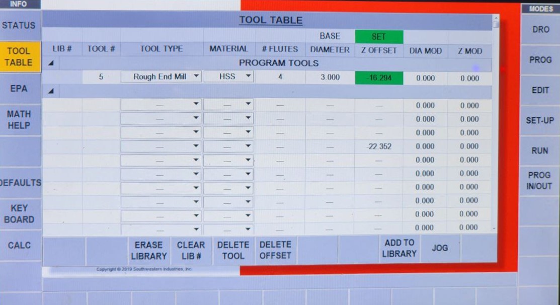
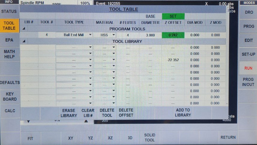
Once the zeroes of X and Y are set, then we change the bit, select the program, and adjust parameters in Tool table, including the Z offset by jogging for large adjustments and manually using the digital Z scale for finer adjustments
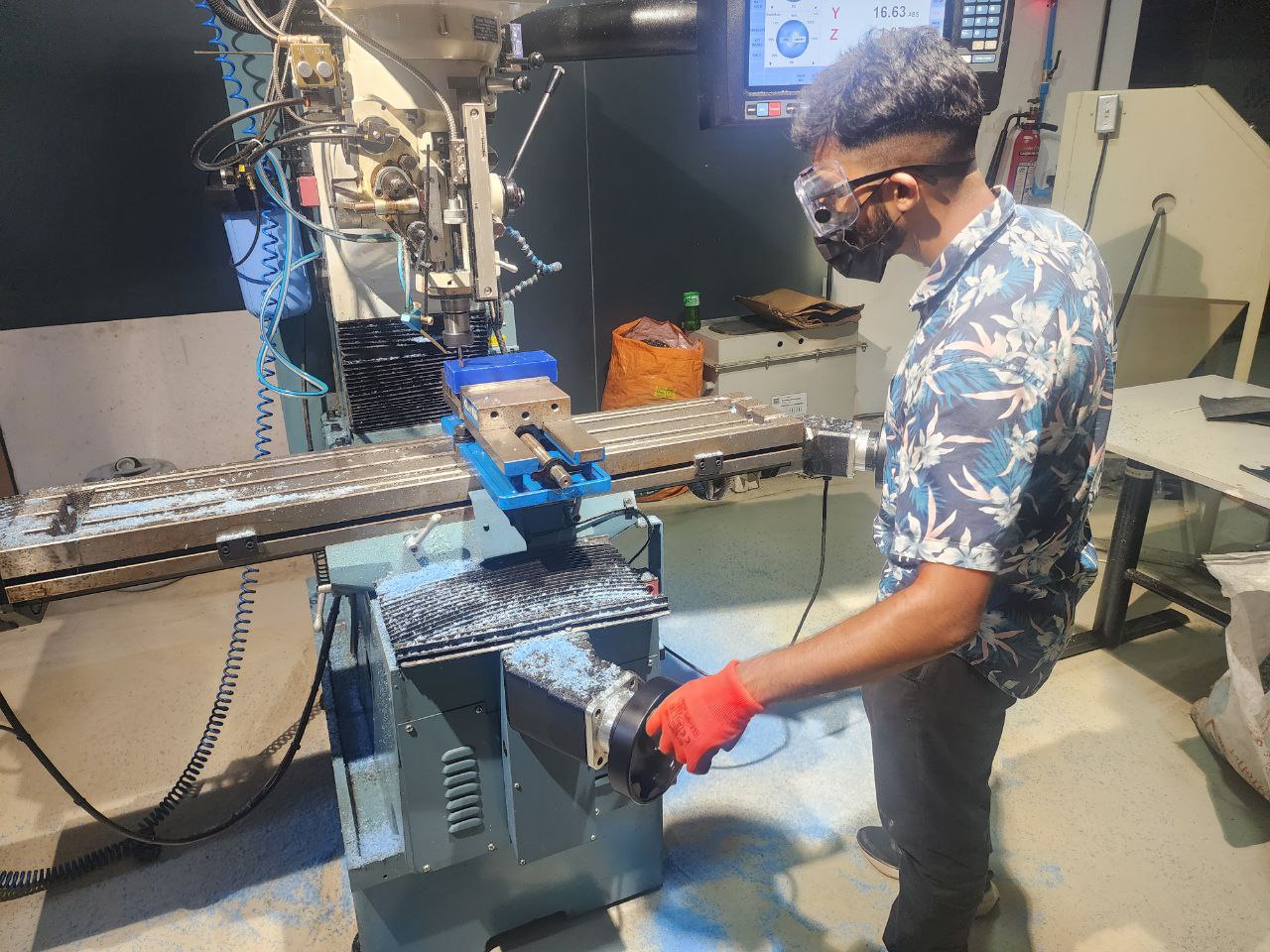
Then we run the program, start Traking manually to make sure that the milling operation is correct. Once confirmed, we start the CNC run
Once done with one operation, repeat the same process for the other bits, adjusting the parameters in the Tooltable each time
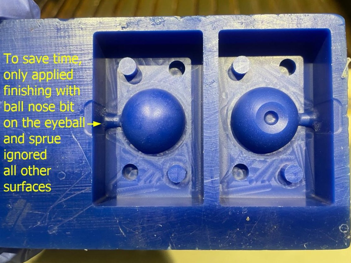
This is how my mold looks like once finished
Making the 'Negative' Silicone Mold
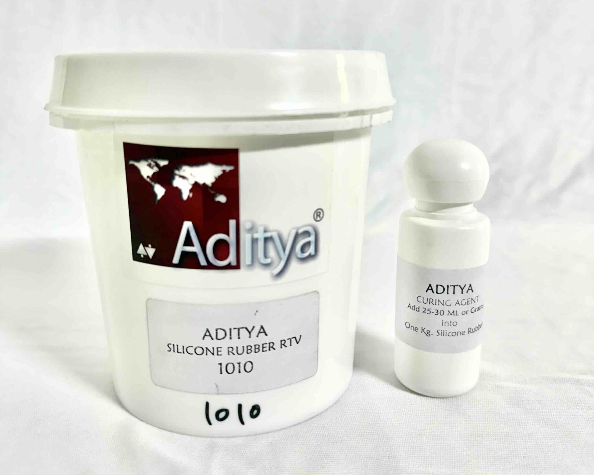
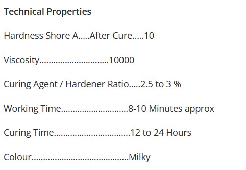
The negative mold will be made using Aditya Silicone Rubber RTV – 1010.
Safety
Refer to the safety data sheet if available for more specific safety measures. Since a proper document was not available, we follow some general practices when working with silicone.
- To prevent contact with skin, always wear gloves when handling silicone. In case of physical contact, wash with soap and water
- If there is any leftover mixture, use it completely in dummy molds and let it cure. Once cured, silicone is inert and is safe to handle
- Use a dedicated space for handling chemicals like silicone and resin to contain any waste produced to one location in the lab
- Segregating chemical waste to be handled by relevant disposal team.
- Avoid eating or drinking near the molding & casting workbench
- Store chemicals in a cool, dry place away from sunlight.
Procedure
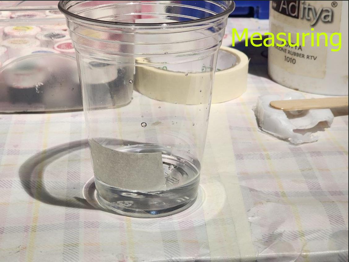
First we measure the amount of liquid that will be required to fill the two molds using water and pour it into a cup. Then, we mark the liquid level using masking tape.
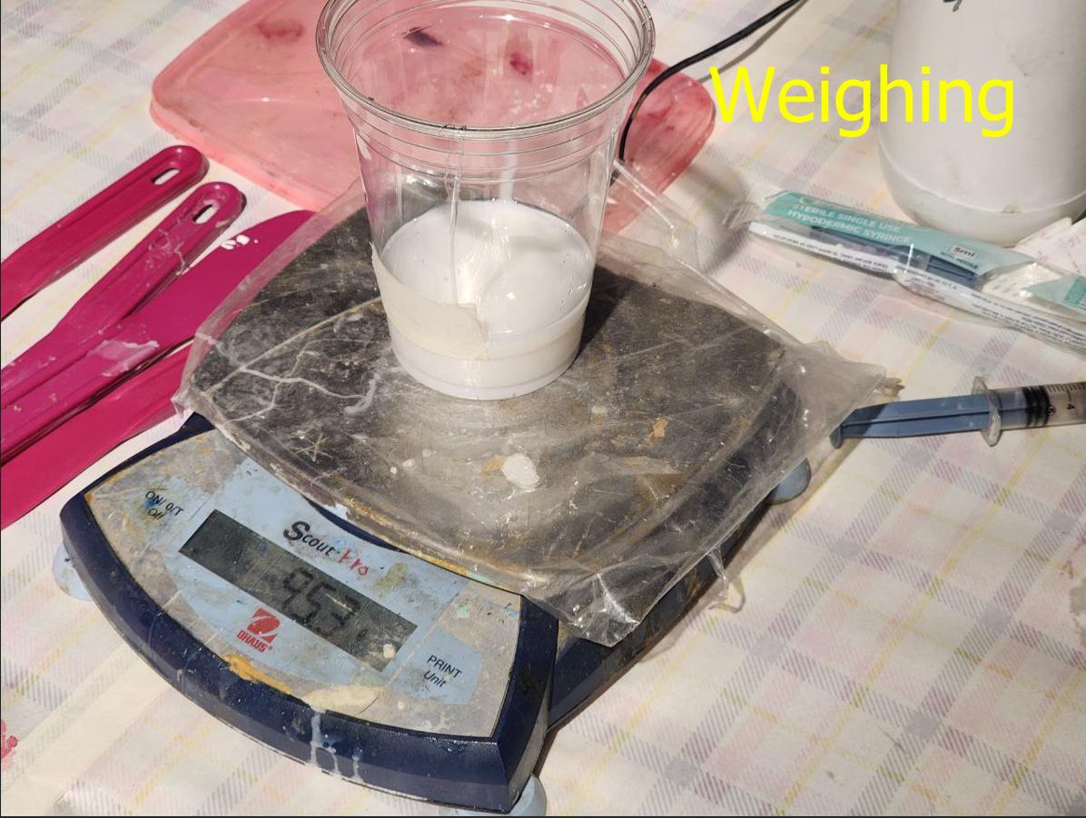
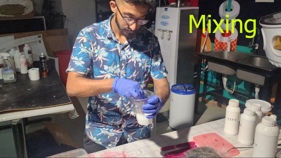
We then dry both the cup and the mold using air blow gun, place it on top of the weighing scale and zero it. We then add silicone upto the same level as marked previously using the masking paper and check the weight of the silicone. We then add curing agent according to the ratio specified on the bottle.
Now we mix thoroughly. Care must be taken to mix thourougly but slowly in a front-and-back motion instead of a circular vortex motion to avoid adding air bubbles
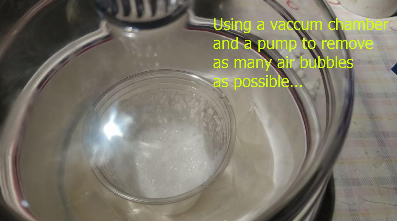
We also use a vaccum pump to remove as many air bubbles from the mixture as possible
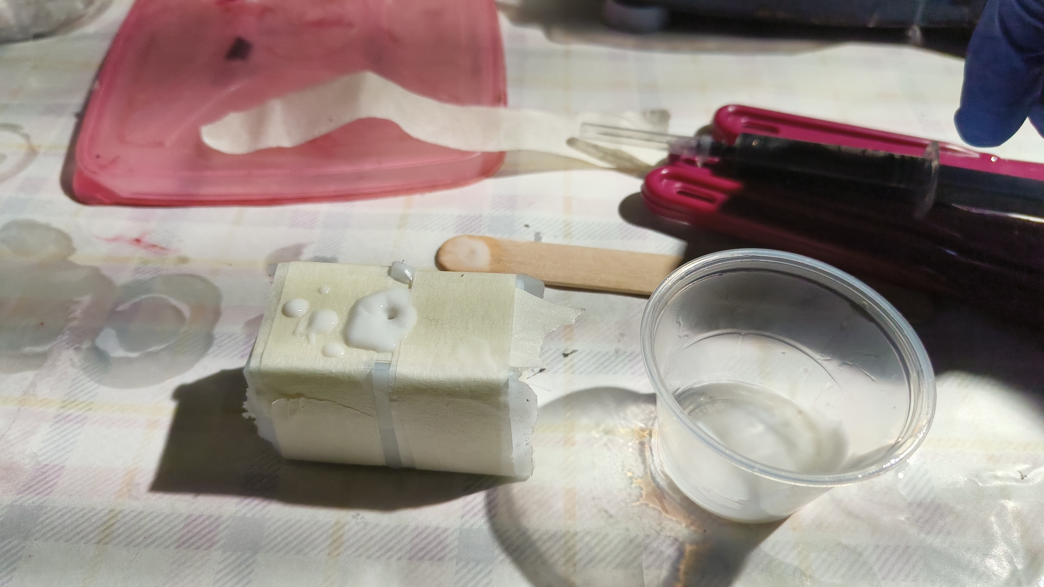
Once done, we pour the mixture into the mold slowly, let it drip in thin threads to avoid air from getting trapped in between while pouring. Additionally, I tap the mold several times once pouring is done to ensure that air is not trapped inside.
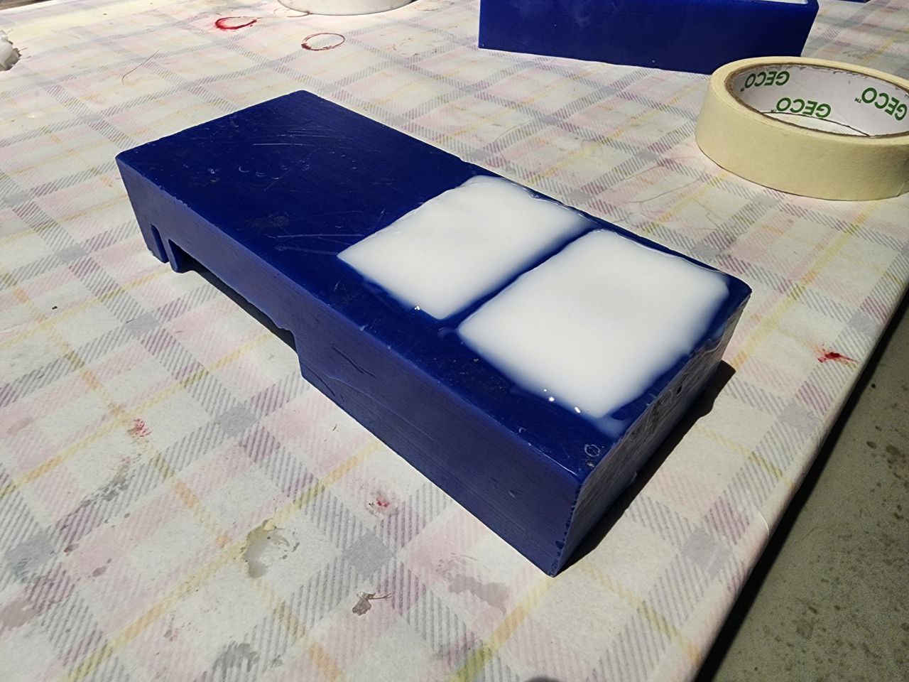
This is how the mold looks like once all this is done
Now we wait for around 24 hours for the silicone to cure. This is how my mold looks like once cured
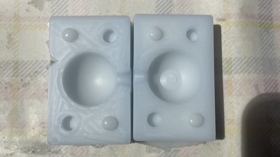
Since I had no air vent, I had to modify the mold a bit by cutting into the silicone to create a second hole
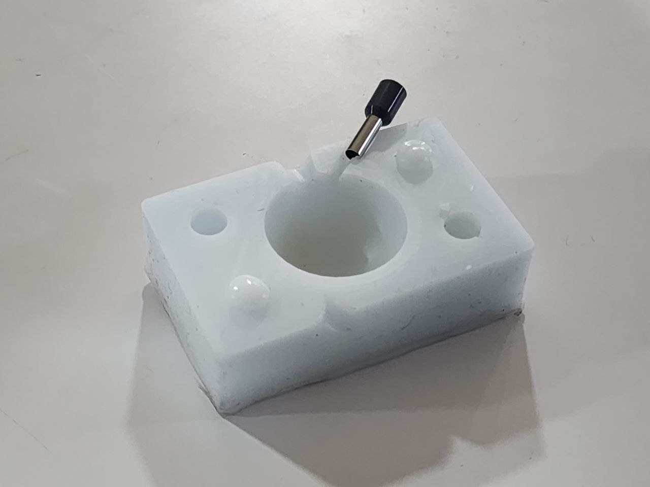
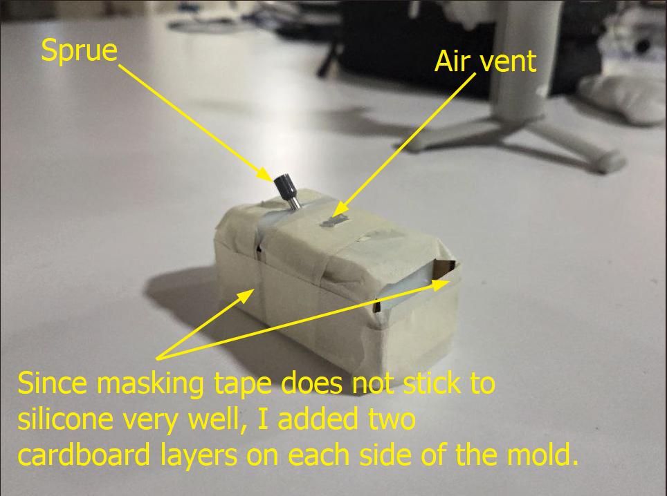
Note that I had forgotten to design an air vent, so I had to cut one half of the silicone mold to make an air vent for air release.
Making the Eyeball
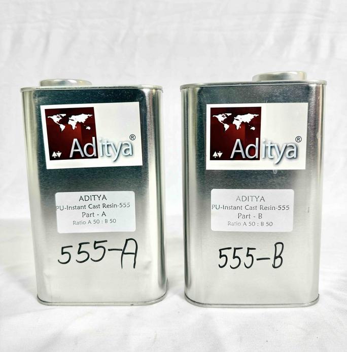
To make the eyeball I used Aditya PU 3 Minutes Cast Resin Milky – 555
Safety
Refer to the safety data sheet (SDS) for specific safety measures when working with resin. In the absence of a detailed SDS, we follow these general best practices for safe handling and usage of resin in the lab.
- We always wear nitrile gloves when handling resin to prevent skin contact.
- We have a designated space for resin mixing and casting to prevent contamination and for easy cleanup.
- We avoid eating, drinking, or touching any parts of exposed skin when working with resin to prevent accidental exposure.
- We store resin and hardeners in tightly sealed containers, in a cool, dry place away from direct sunlight.
- Cast any unused resin in dummy molds and let them cure—do not pour down the drain.
Procedure
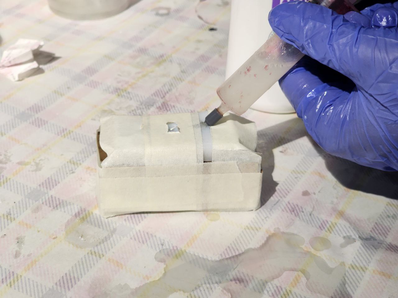
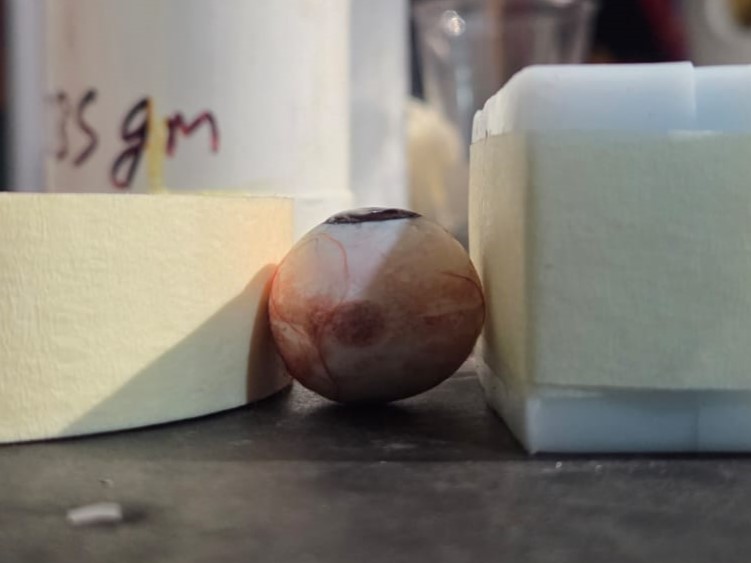
I injected the mixture into the mold using the new sprue I created
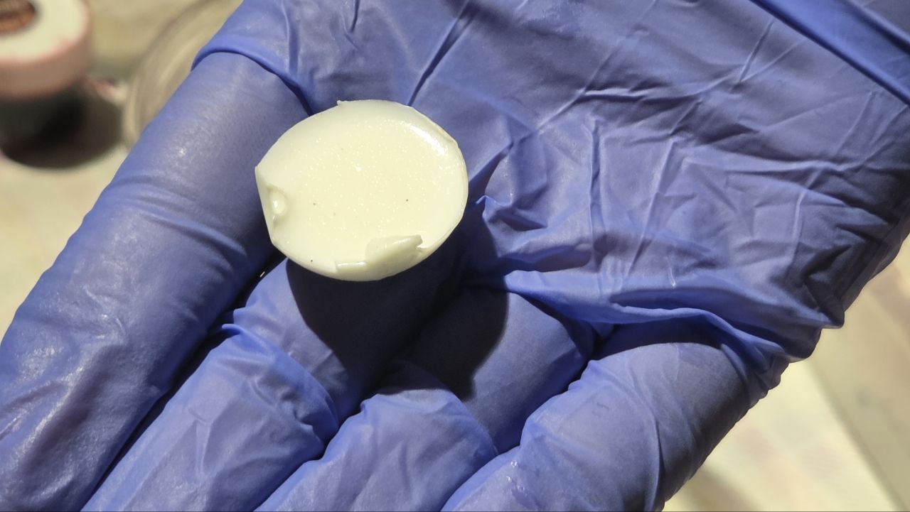
This is how it looks like once cured
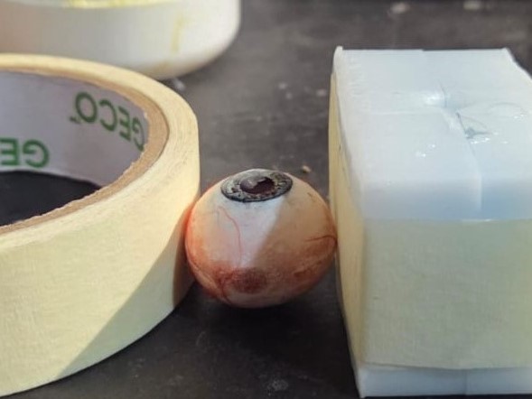
This is how it looks like post cutting using pliers and sanding
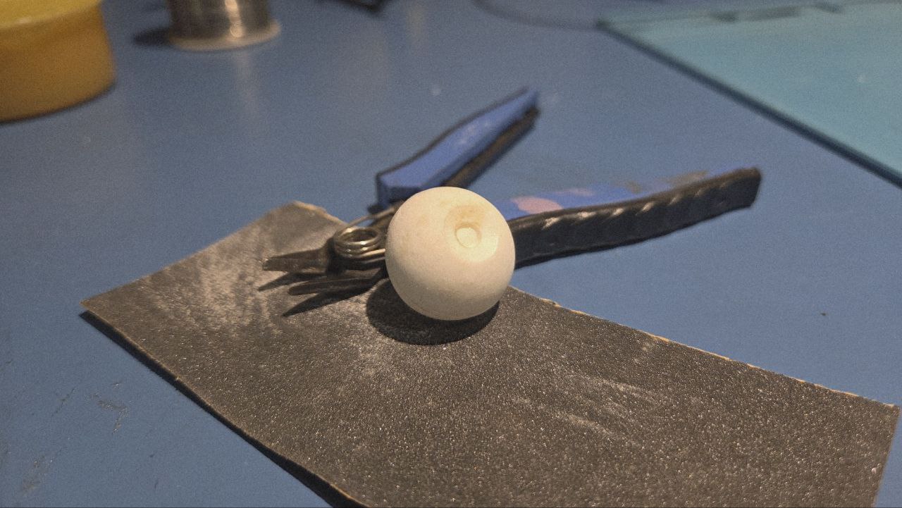
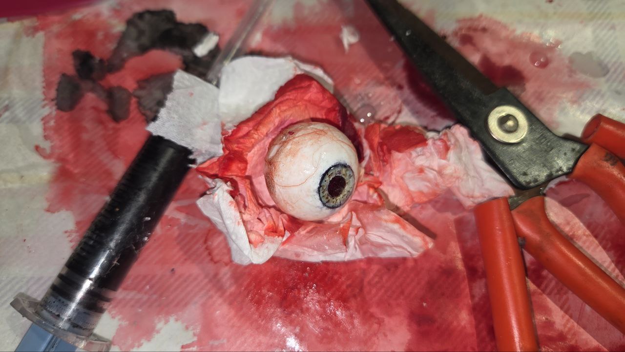
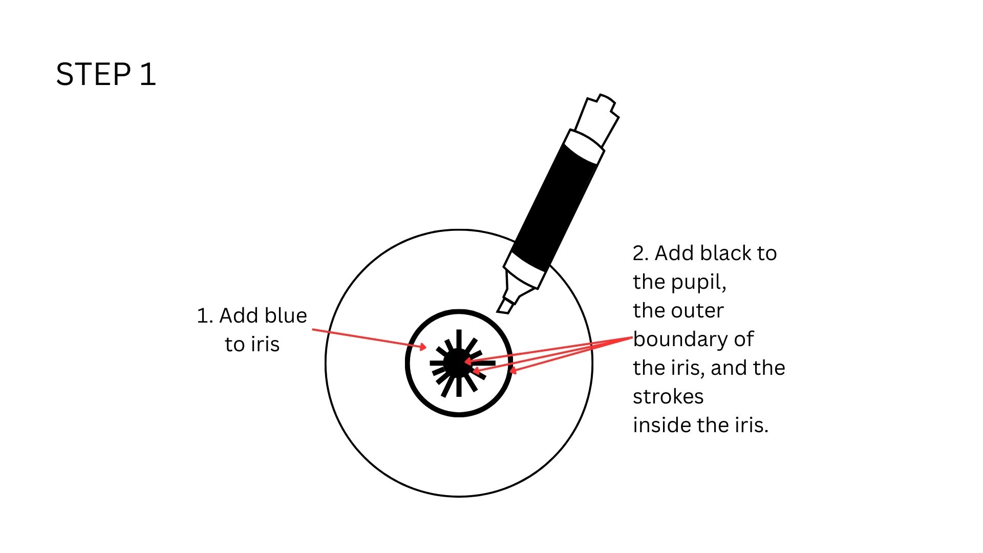
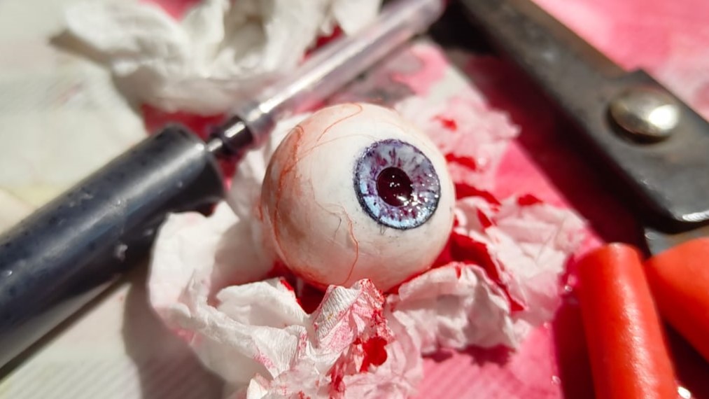
Detailing
To make it look realistic, I will be following the below given steps, adapted from those given in the previously mentioned instructable for my purpose. I used black, red, and blue permanent markers, Flex Kwik, satin thread I took from some red ribbon to achieve the desired effect.
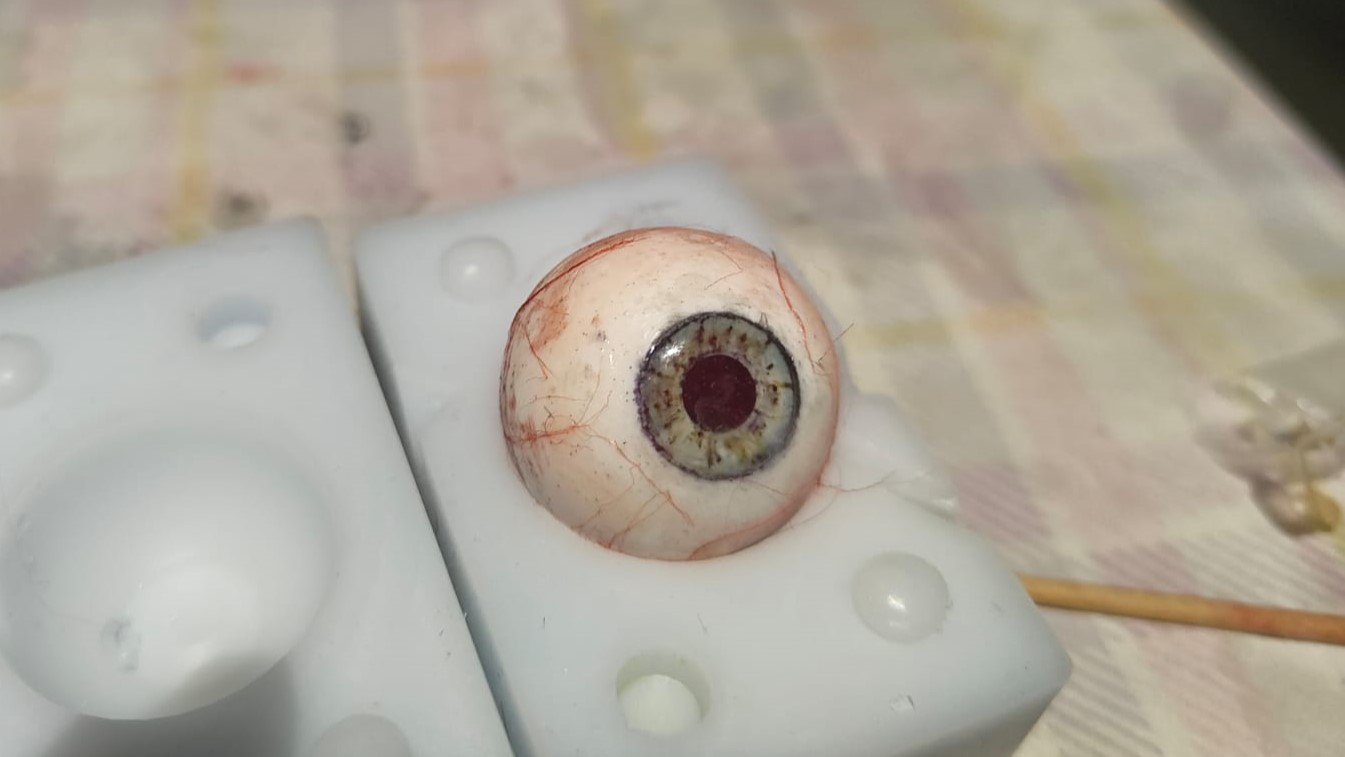
This is how it looks like once done. Note how the original blue has mixed with black to create a more darker colour, which still looks realistic.
This is how it looks like before adding transparent resin to the iris
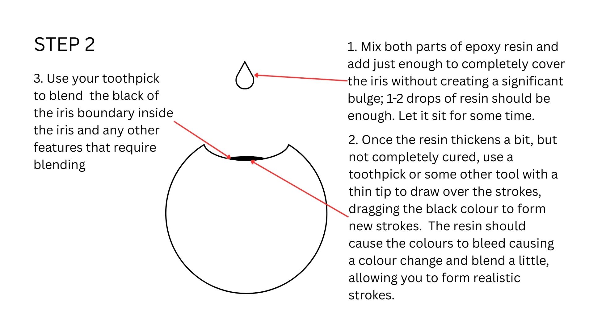
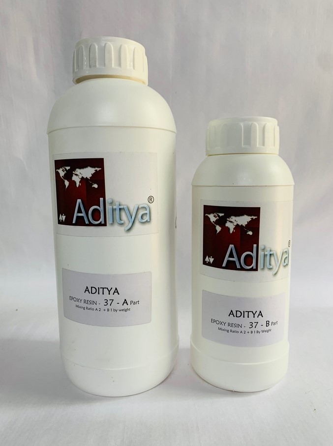
Adding Resin
Then I added resin to the iris. I will be using Aditya Ultra Clear Cast Epoxy.
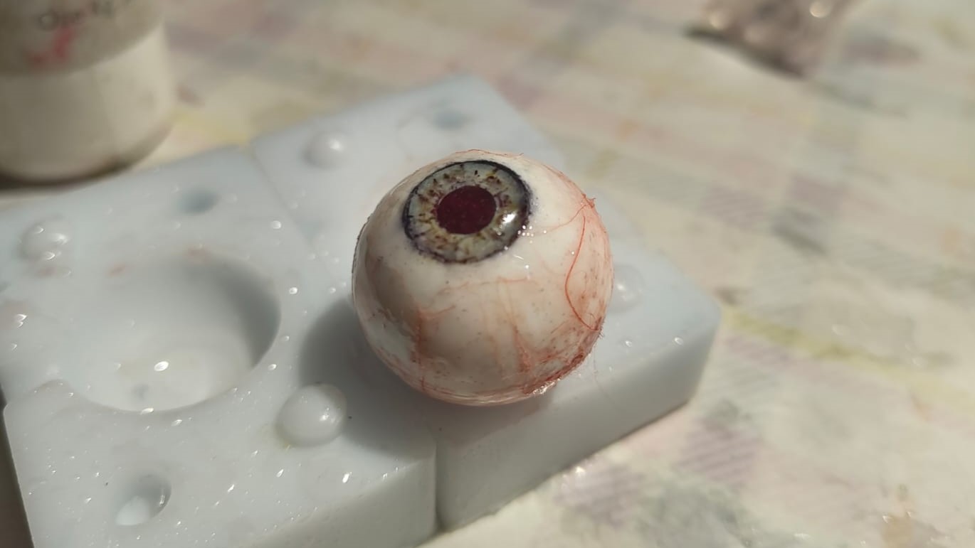
As you can see the colours have mixed even further becuase I did not wait enough time for the initial coat of resin to cure.
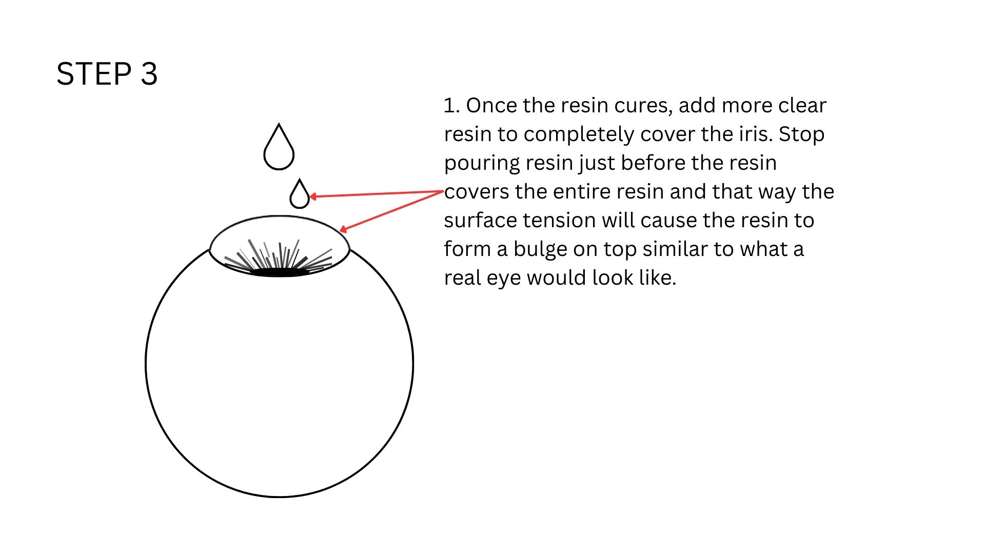
This is how it looks like once cured. Once the iris was cured, I mixed some more resin and added it to the the white of the eye to create a glossy finish and protect the all the detailing from the external environment
Conclusion
Mistakes & Solutions
-
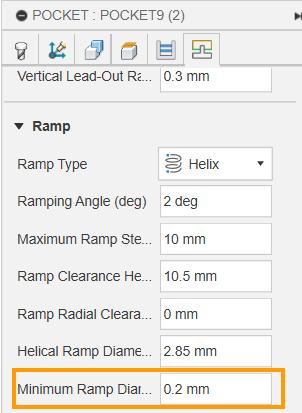
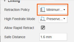
Pocket operation not cutting the hole: The pocket error was solved by my instructor Saheen, when the minimum ramp diameter was reduced to 0.2 mm. Also, The warning related to retraction was removed when the retraction policy was set to minimum
- No air vent in the design of the mold: Your mold will need one air vent to allow air to escape and one sprue that allows resin to be poured in
- Colour for resin casts: The resin would cause the colours of the marker to bleed out three different times, the strokes I made for the iris were affected. If I had to try this once more, I would look at other aternatives for paint, or a way to bind paint to the surface in a way that prevents the resin to affect the colours.
- Shortening resin curing time: We tried reducing the curing time using the vaccum chamber, but doing so can cause the transparency of the cured surface to be reduced.
References
References to help reader understand in detail