Week 7: Computer Controlled Machining
Objectives
These are the objectives for this week:
- Group Assignment
- Do your lab's safety training
- Test runout, alignment, fixturing, speeds, feeds, materials, and toolpaths for your machine.
- Individual Assignment
- make (design+mill+assemble) something big (~meter-scale)
- extra credit: don't use fasteners or glue
- extra credit: include curved surfaces
Group Assignment
You can see our group documentation here
Individual Assignment
Inital Design
First we take multiple measurements of the plywood sheet. For me, I got the following values: 17.17, 17.50, 17.22, 17.46, 17.28, 17.67. Average value is 17.383. The I test if a rough shape of my final design for a standing desk would fit in the 8x4 feet of plywood.
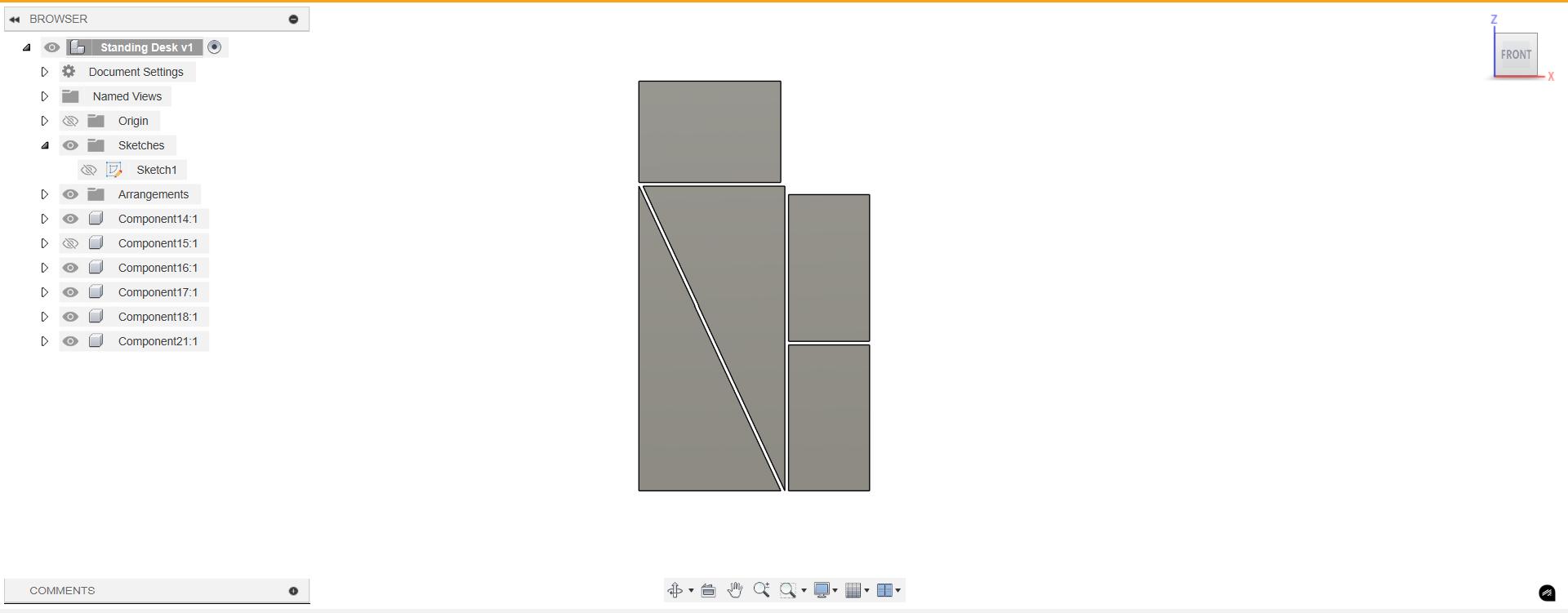
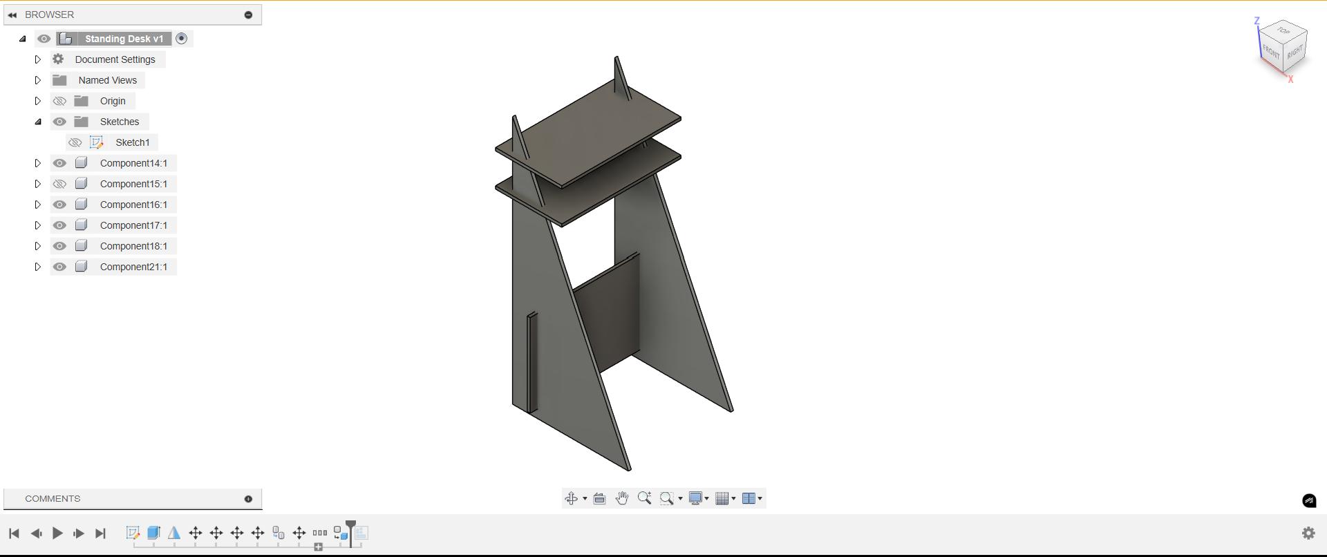
Once I was confident it would fit, I experimented with different shapes but I was not satisfied so I rethought my design taking inspiration from an already existing design.
Sketch is made in such a way to waste as less material as possible
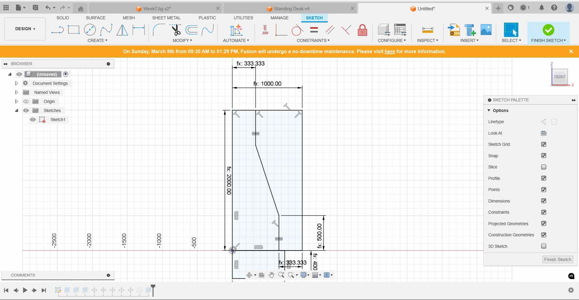
I made the first version of my standing desk.
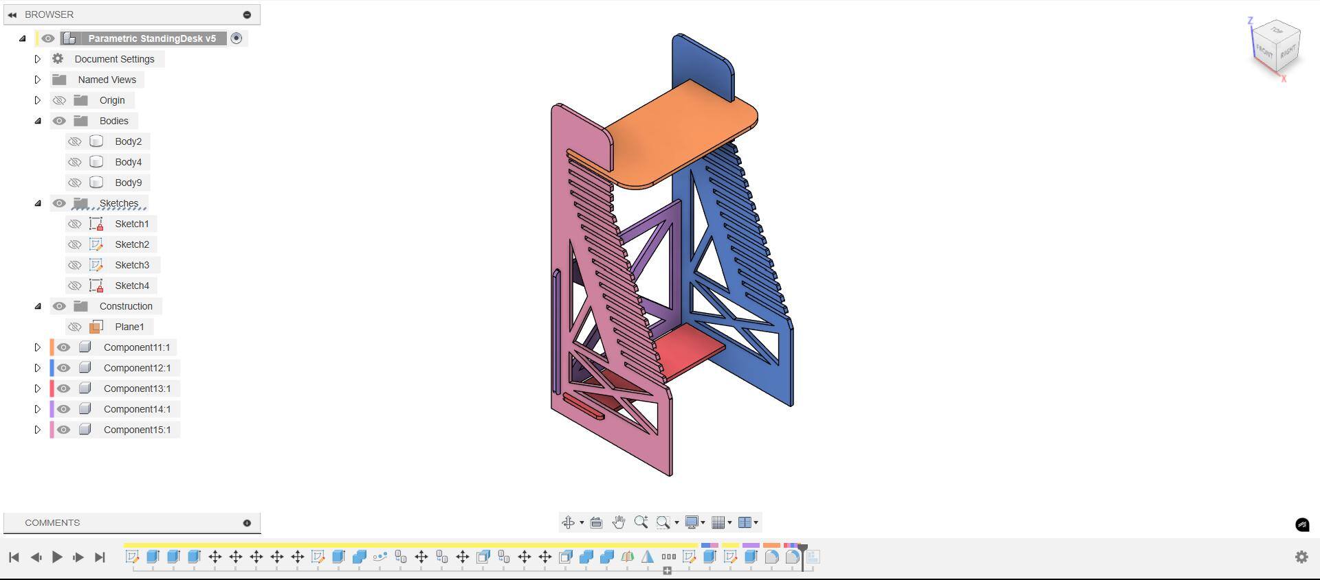
Iterations
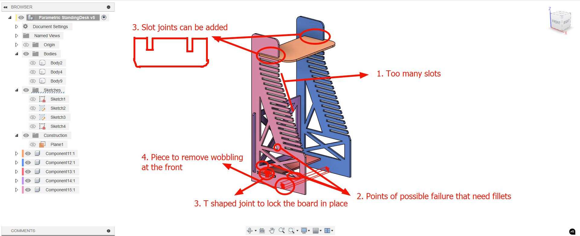
Based on feedback from my instructor Mufeed, there were many issues with my design that need to be corrected
- The number of slots will take too much time to be machined. A couple of slots at the top for standing position and a couple of gaps near the bottom for the sitting position only are required.
- There are weak points in the structural members of the desk, an easy fix is to add a large fillet to all of them (~15 mm)
- Slot joints can be added to the table top itself to reduce the total length of the gaps in the side pieces. Also, it helps to ensure that the table top is always pressed into the right position.
- Finger joints can be added to the structural supports
- A T shaped key can be added to lock the horizontal support in place
- To avoid wobbling at the front, a board can be near the front with slot joints on the board and the corresponding slots can be added into the side panels itself
Revised Idea
Instead of slots, I was inspired by this design by Rahul (FA 2017, Fab Lab Trivandrum) and wanted to incroporate his saw tooth mechanism to be able to adjust the height.
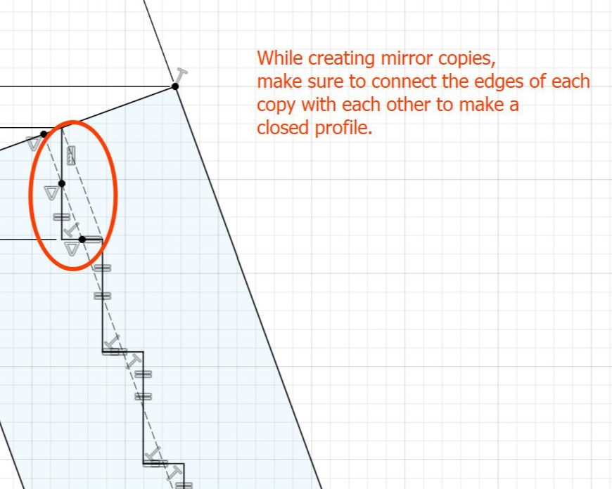
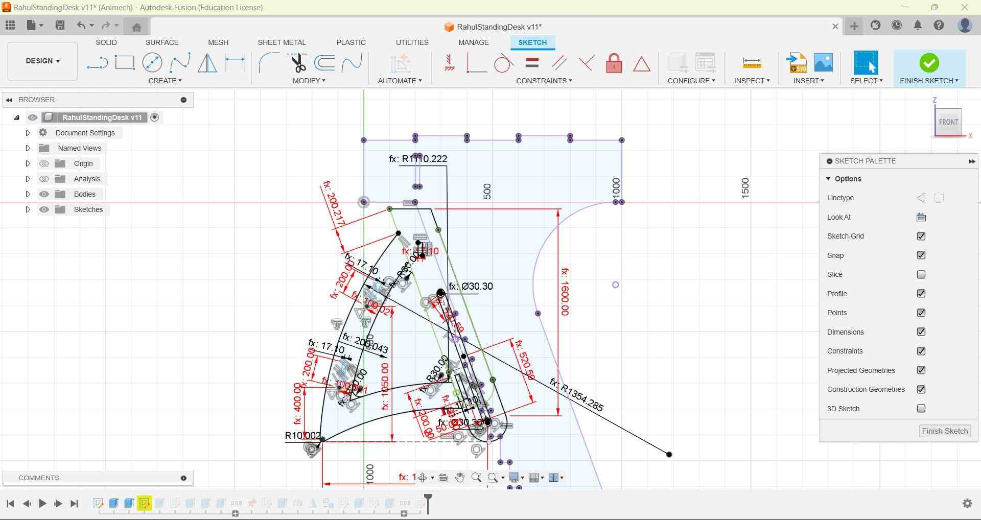
While using Rectangular pattern, one has to make sure that each copy touches each other and the corresponding points are coincident, otherwise you wont be able to extrude the profile.
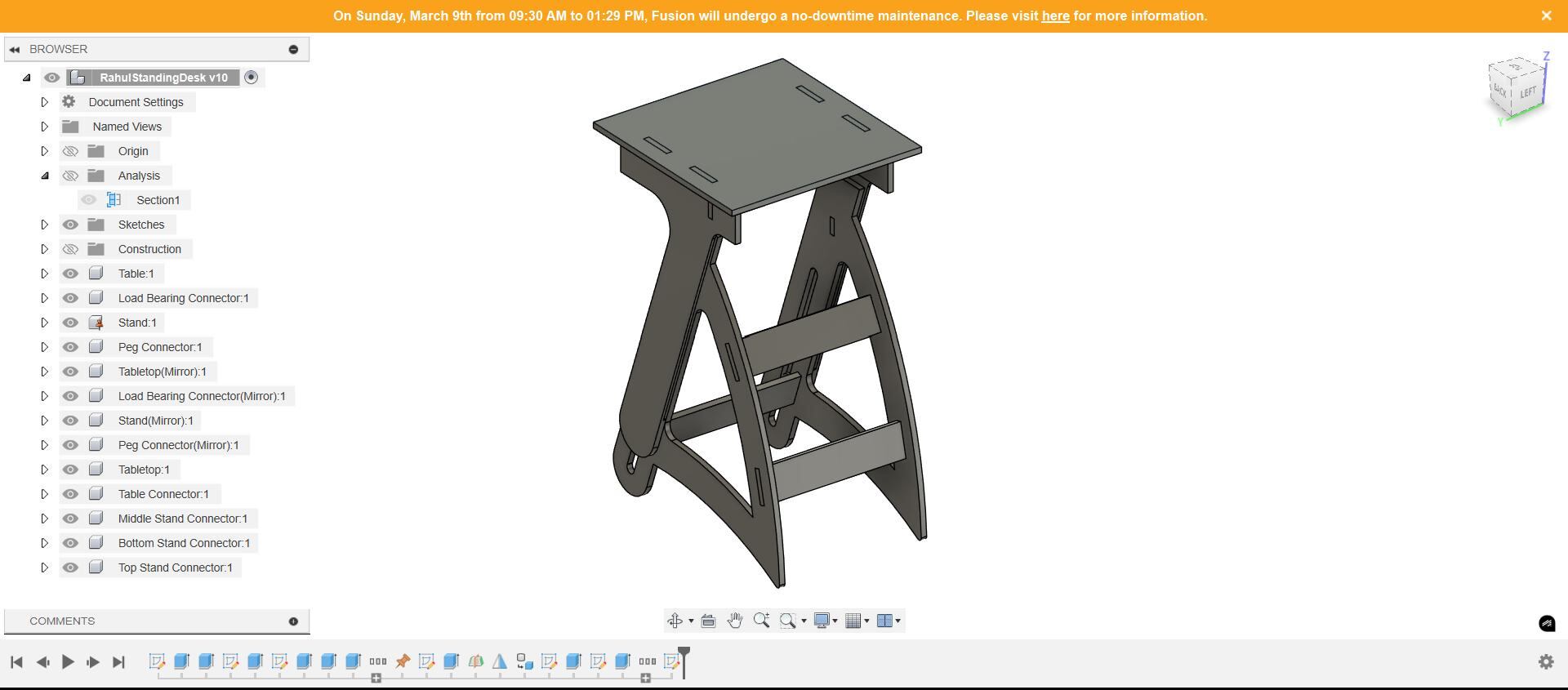
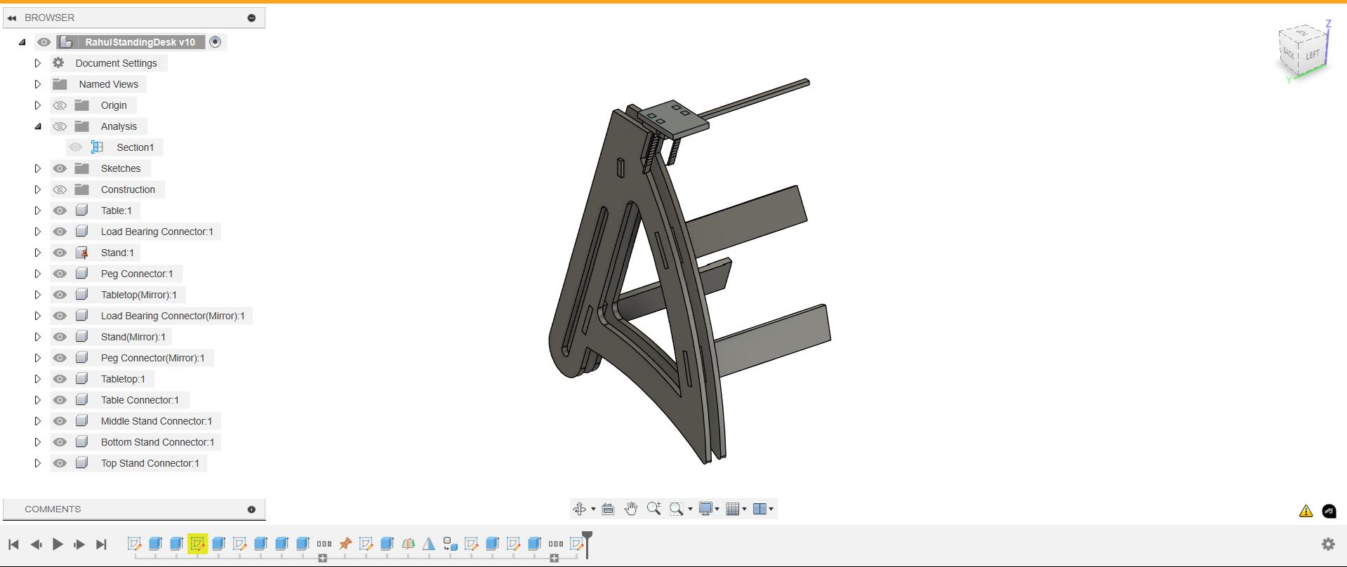
It's also important to check your design is parametric from time to time by changing the scale. In my case, the curve of the leg kept changing when the scaling factor was changed because it is linked to 'Depth' parameter which was not parametric. Similarly, the steps were not changing in proportion with the rest of the body, so I relinked it with the height parameter instead of the depth parameter.
Finally, I was done with the design, but unfortunately it was not parametric, so I went back to the initial sketches to correct the issue
Laser Cut Mockup
There was an error with design of the peg, which would cause it to be cut in the middle in the laser cutter, so I corrected that
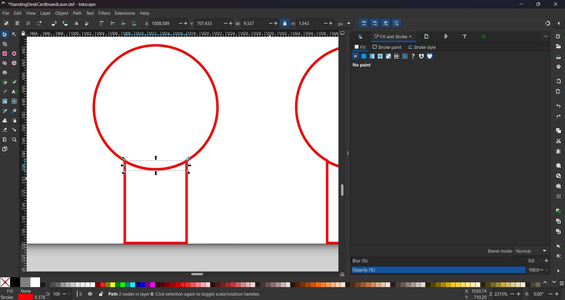
PegError.jpg)
-PegError.jpg)
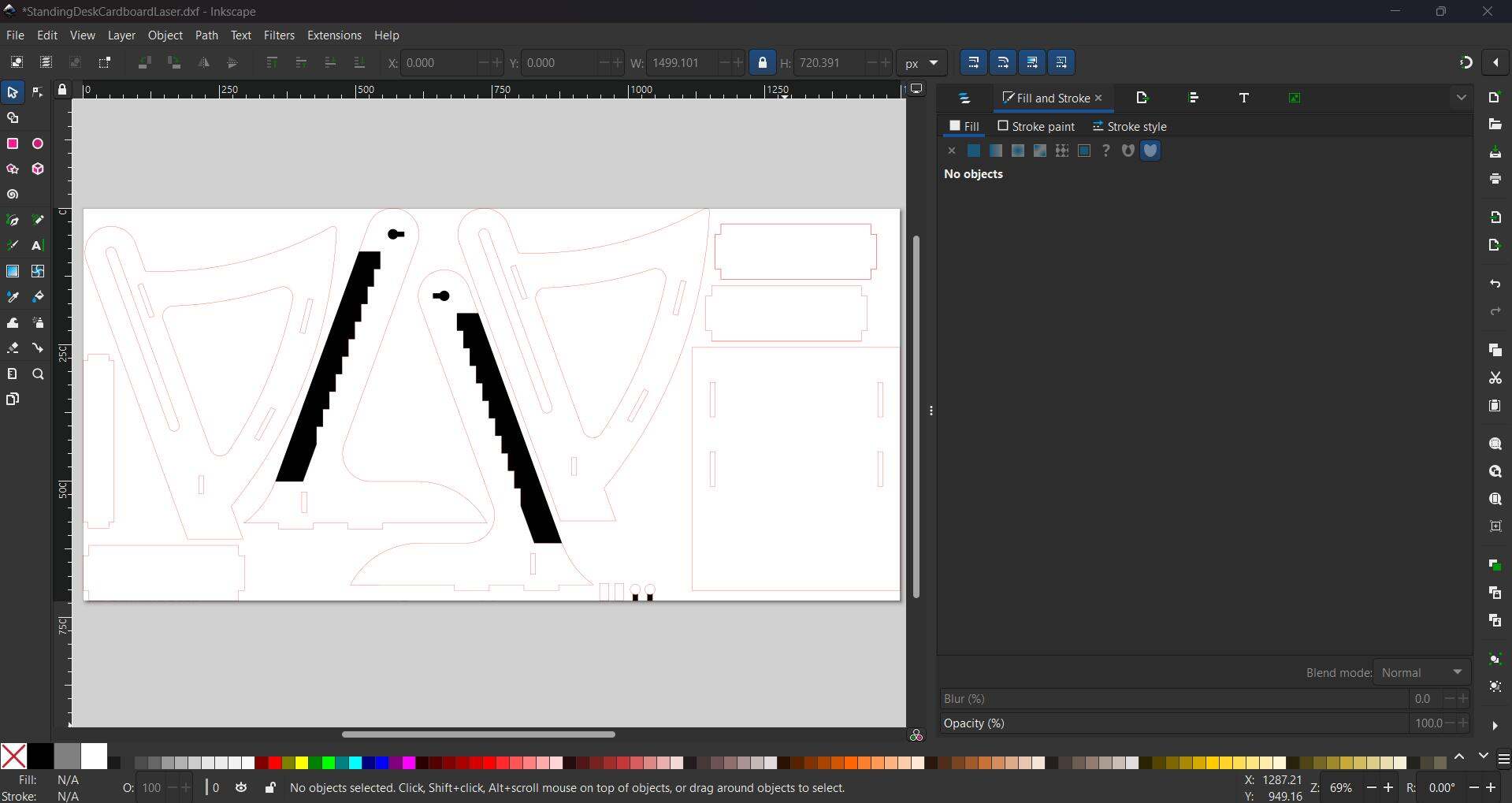
This is how it looks in SVG before laser cutting
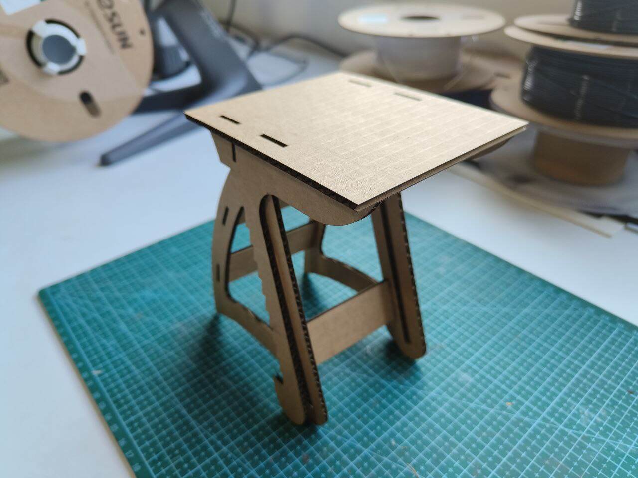
This is how my model prototype looks like in cardboard
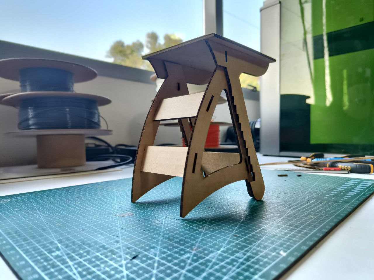
Problems:
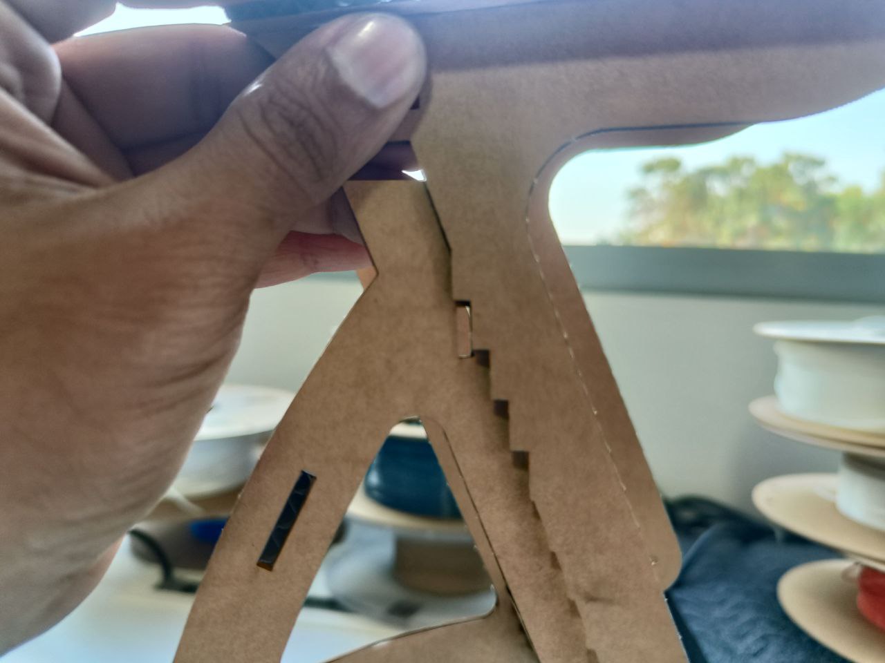
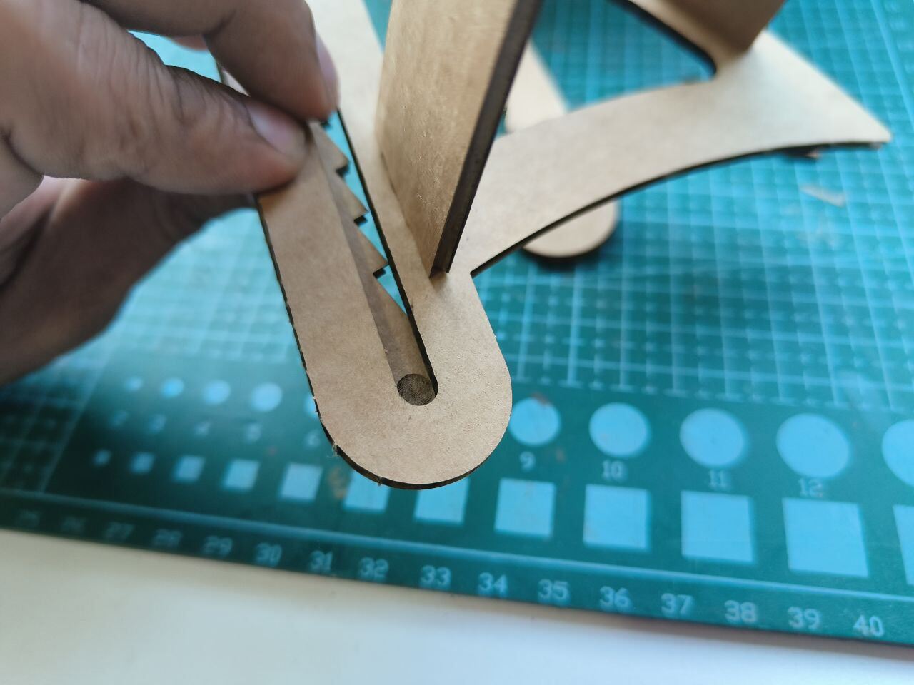
- Since the peg and the load bearing joint I made is too small and because the engraving was too shallow, I was not able to get the table top to move like I had designed.
- I did not remove the stroke in the steps of the sides, so the laser cutter completely removed the portion which should have been engraved.Solution: Use two cardboard layers for the thickness in the side, one layer where only half the thickness is required.
- The peg should fit in here to control the direction in which you can pull the tabletop.
- The entire table sits at a minimum height of ~90 cm, which is close to the height I need for a standing table (ie. close to the maximum possible height). This means that the table cannot be used for sitting position, which is why I wanted the adjustable concept in the first place
Modifications
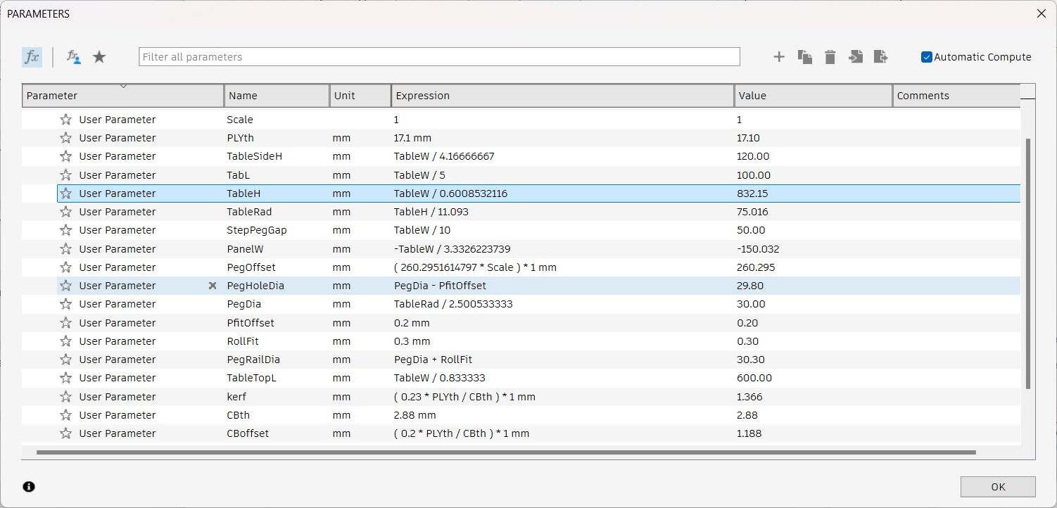
Redefining and revising parameters
Too many parameters and my final model is not completely parametric, in the process of simplifying while modifying original design
A round peg is required to allow the top desk to be rotated back and pulled onto the next step. So I cannot change that feature into something more rectangular.
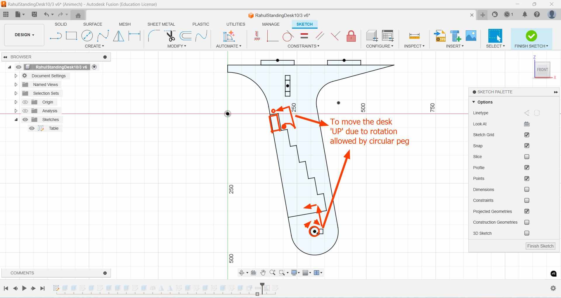
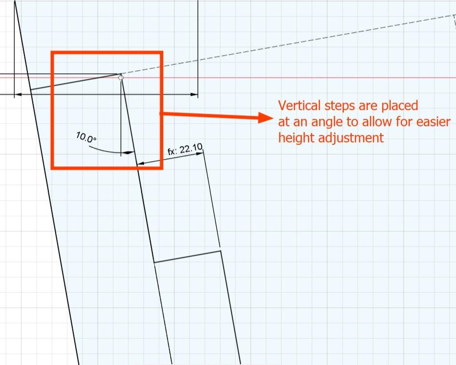
The vertical steps are kept at an angle instead of vertical to allow for easier height adjustment.
To avoid screwing the peg, I made the peg is made of two parts. The first part is a semcircular shape that will 'lock' into place in the pocket of the side leg, making a tight fit that does not require screws
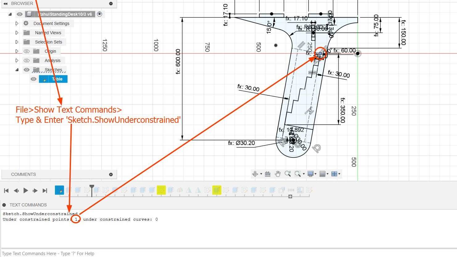
A useful trick to understand which which parts of a sketch is underconstrained is to use text commandsand zoom into the highlighted section
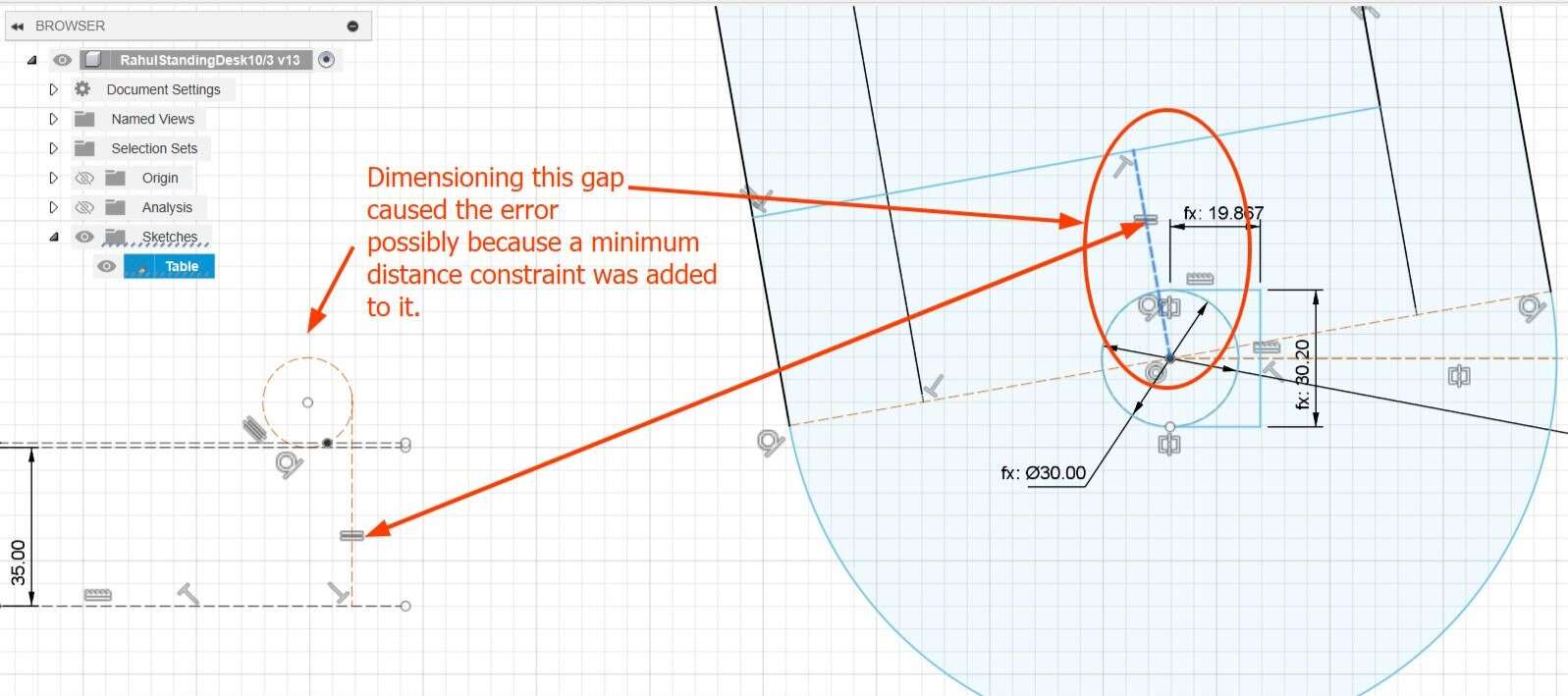
I created a minimum distance constraint between the steps and the circle using this tutorial
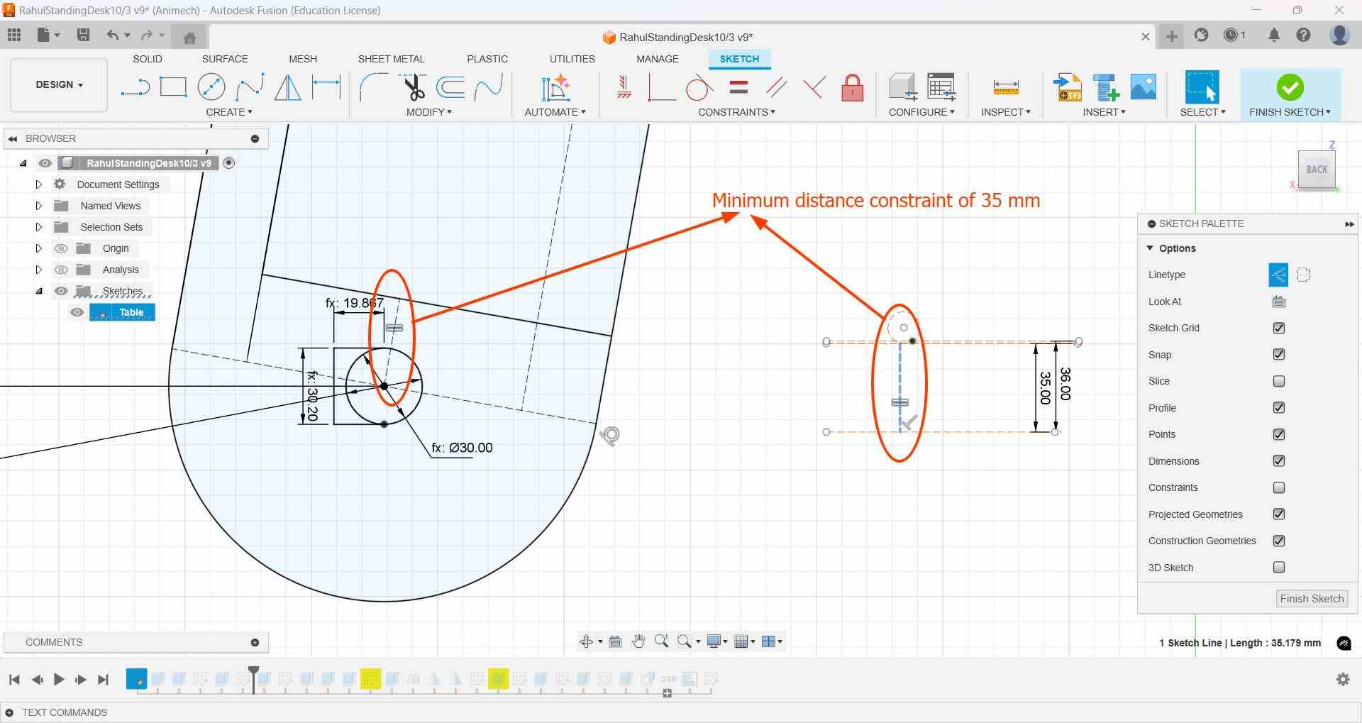
But later I got an error in my sketch due to too many constraints. After deleting and relinking each overconstrained dimension to see which dimension is causing the error, I was able to determine that the cause of the error was the dimension I added for the gap between the last step and the peg.
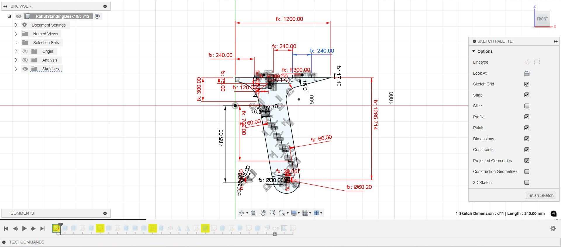
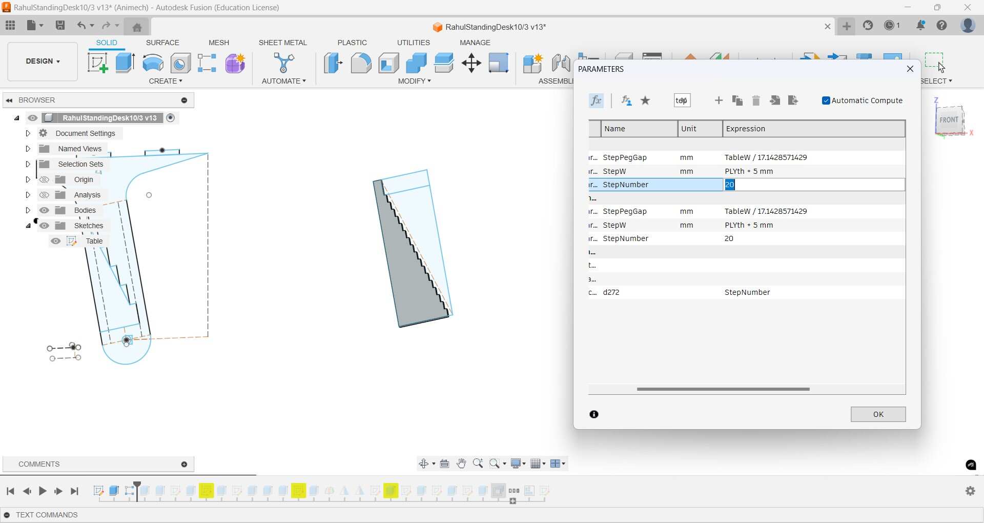
Based off this tutorialI experimented with making the number of steps a parameter also with a minimum length equal to the thickness of the stock material, but I was not able to get it to work so I went with sketching like I did before
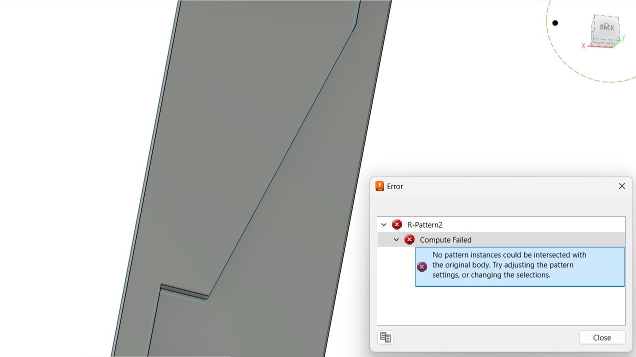
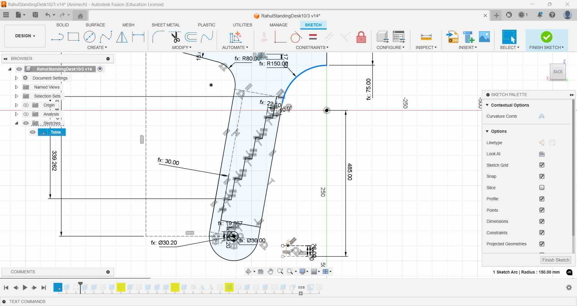
Sketch referencing lost, deleted it and got a red coloured face as a result, I ignored it and latee it went away after I completed all teh changes I was making in the timeline
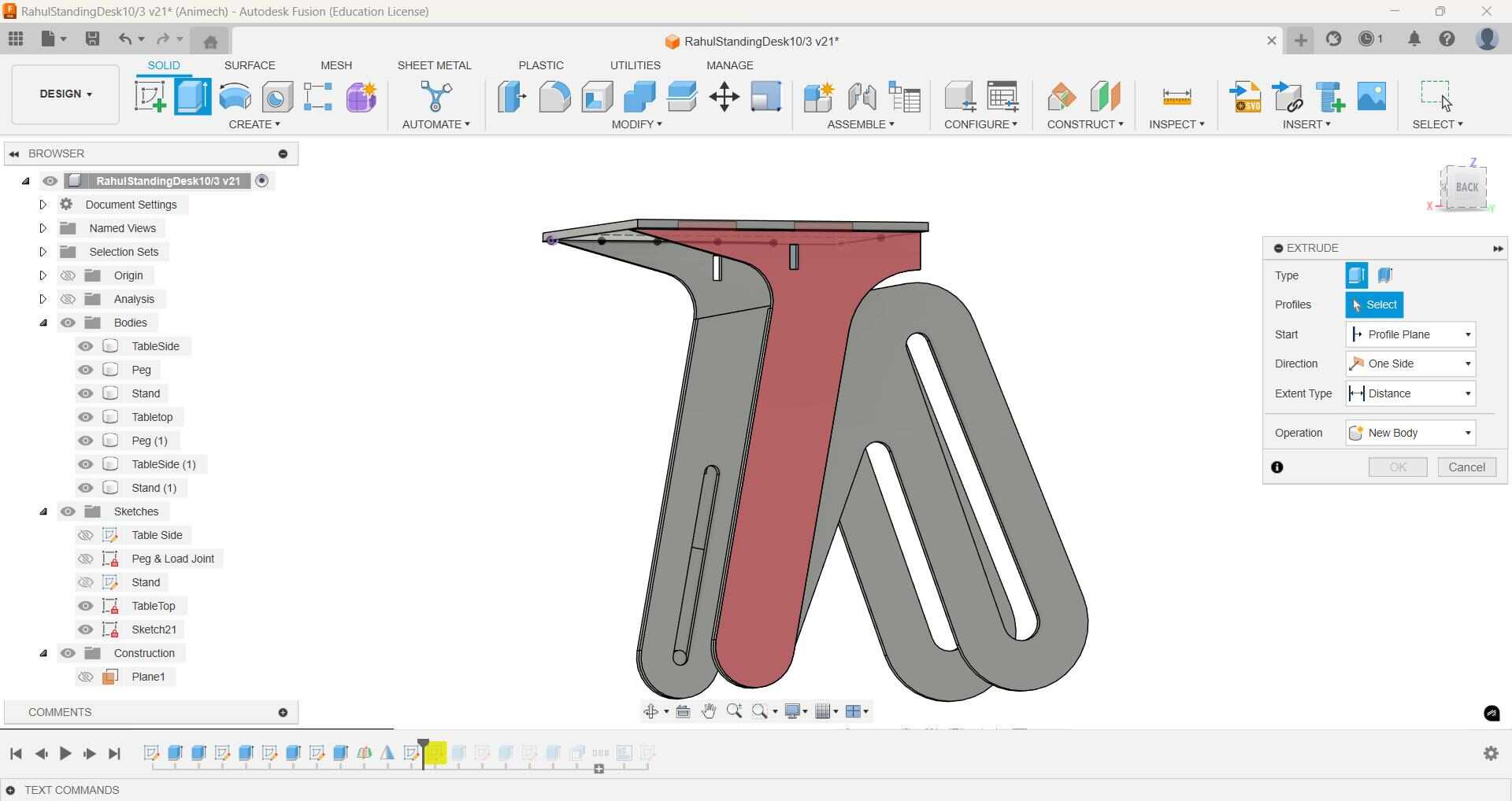
Forgot about extending the extrusion beyond the width of the lower stand to be able to touch the the steps of the upper table portion. Used Press-pull to correct it
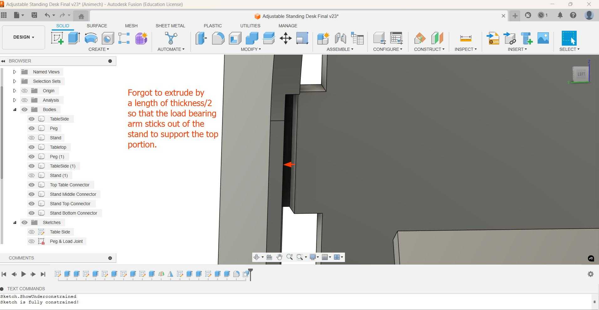
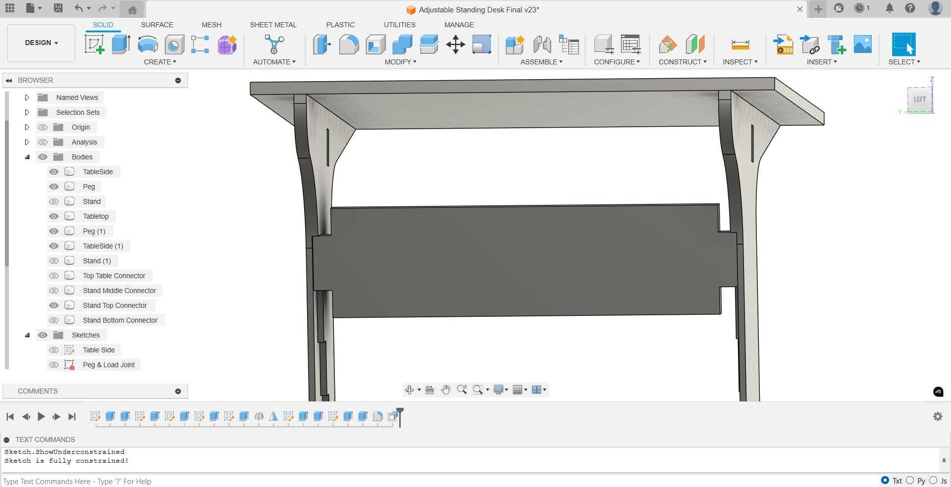
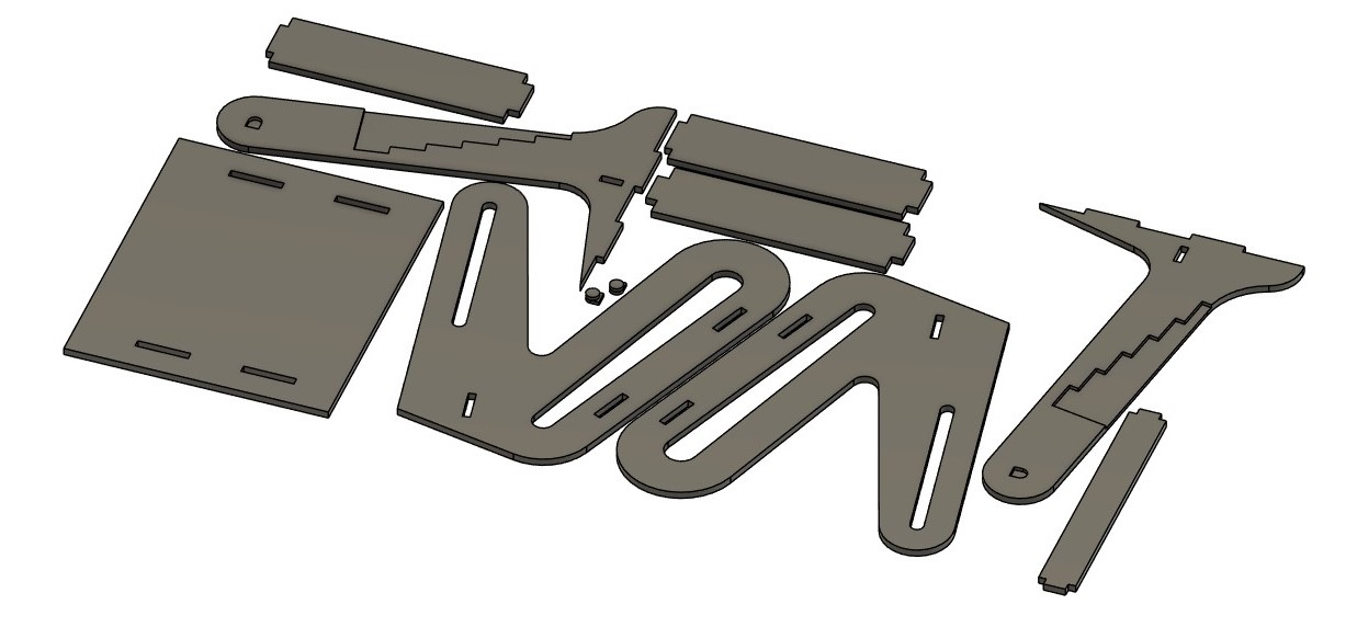
I then arranged all of them.
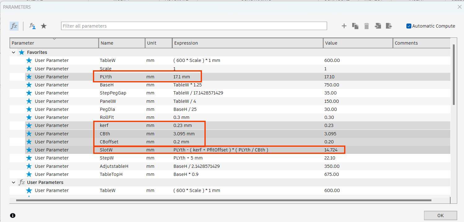
Because my model was not completely parametric, I took some advice from Ancy & Akash in order to be able to scale my model down without affecting thickness and kerf. What I did was scale down my model according to the ratio between plywood thickness and cardboard thickness in Fusion using the command (not my parameter) and I would multiply both kerf and offset by the inverse of this ratio; then subtract the sum from the material thickness (plywood)to get corrected value for cardboard slots. I would now replace all the dimensions of slot width with this new value, called 'SlotW'
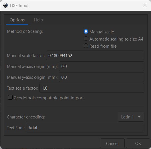
Since I was not able to scale it in Fusion the exact way I wanted to and because I needed to use Inkscape anyway for lasercutting, I went to Inkscape to scale it down according to the ratio of the Cardboard thickness to Plywood thickness
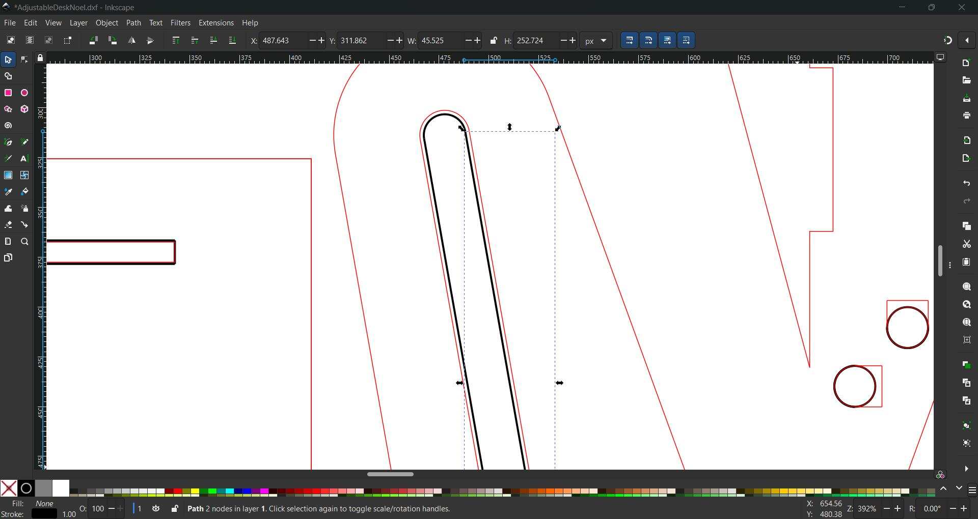
Some unwanted sketches were also imported which I then proceeded to delete. All of the construction lines also got imported as black lines which had to be deleted.
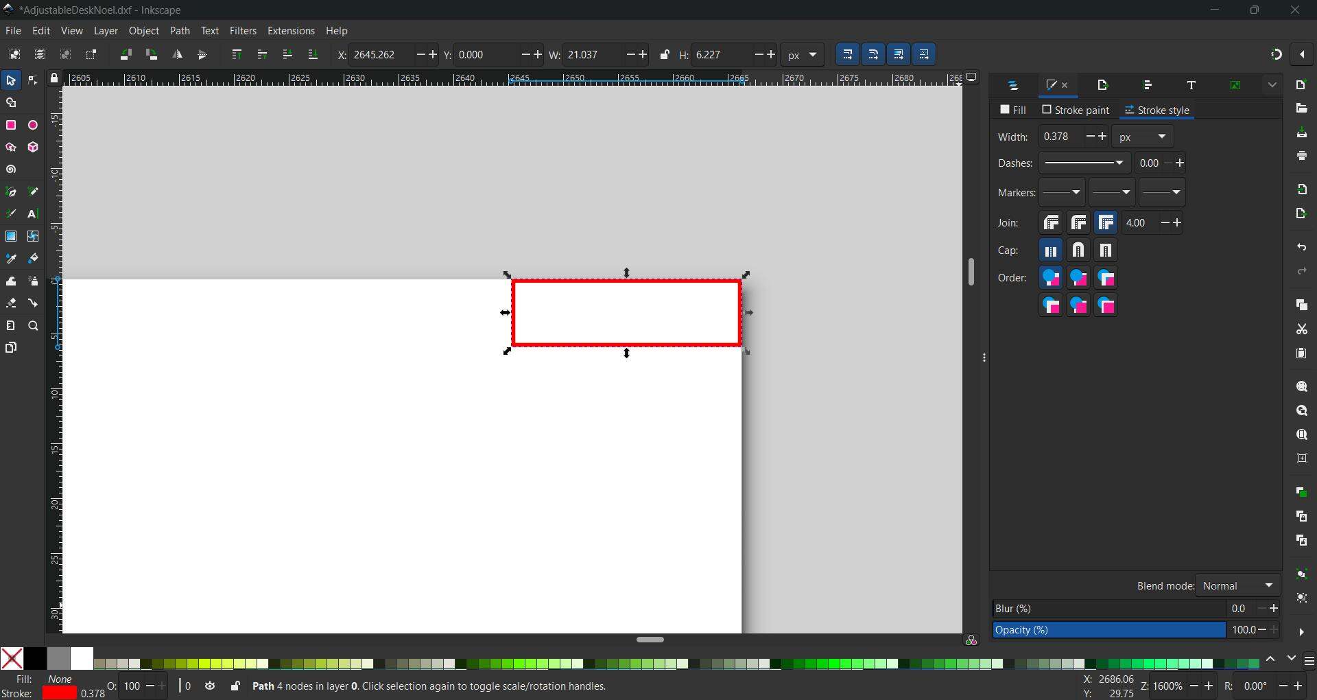
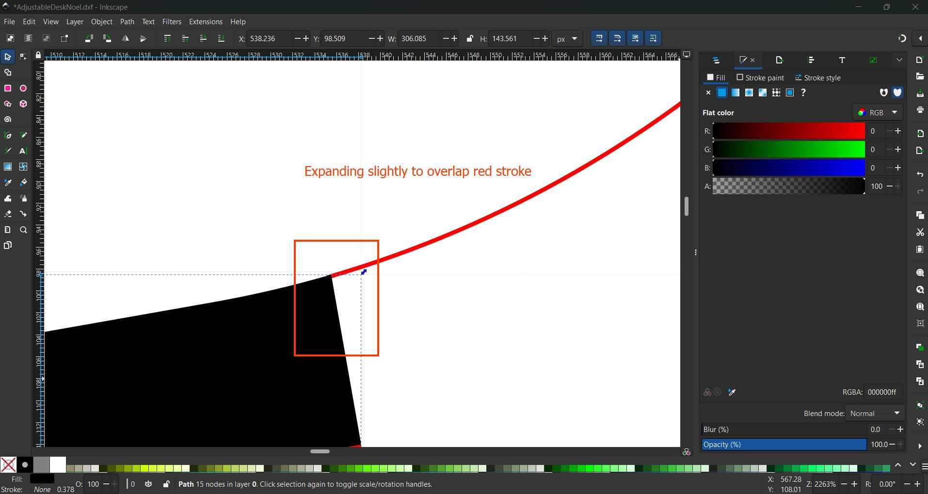
To engrave, first I remove the stroke of the shape of the steps, fill it black and use the cut operation to remove the overlapping strokes in the shape below it hierarchically. This did not work, so in the interest of time, I just removed the portions to be engraved.
Toolpath
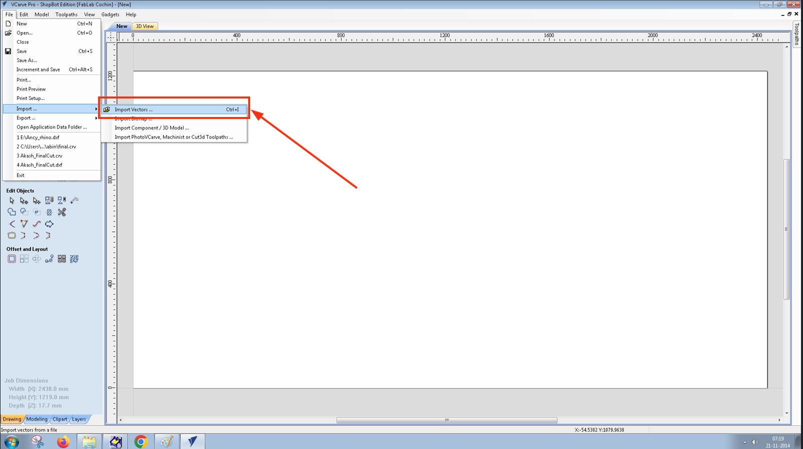
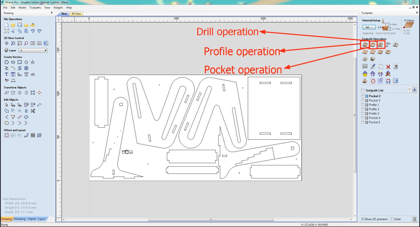
For CAM, we used VCarve before cutting on the Shopbot. First we open the Vcarve application, start a new file, import our dxf file and adjust Job Size and Material Thickness based on the specifications of the plywood sheet we were given
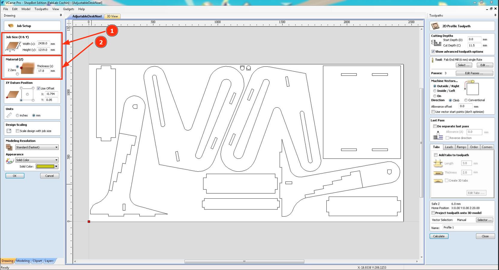
First we add dogbones to the holes and inner edges to remove the extra area that will obstruct panels while assembling everything
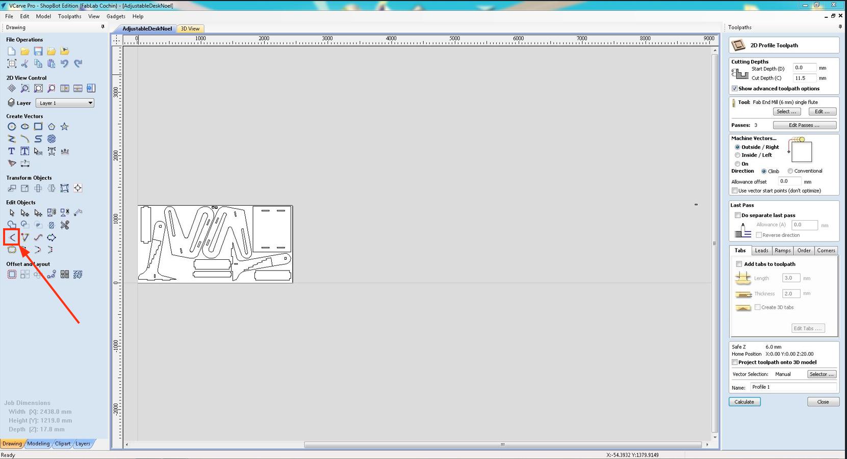
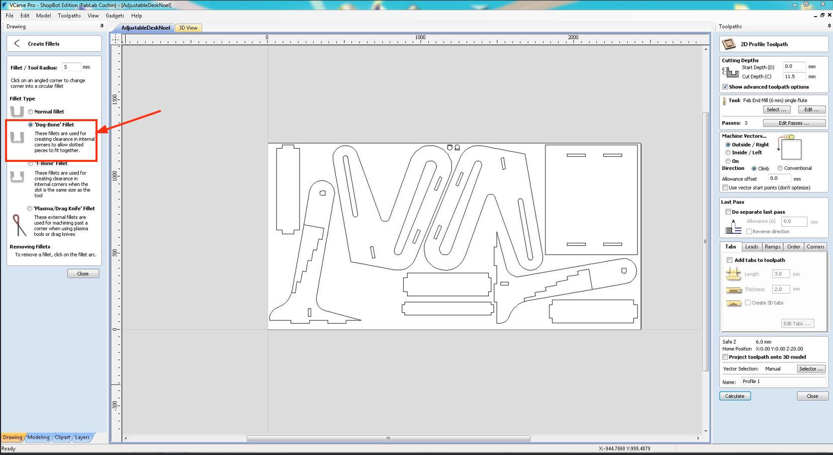
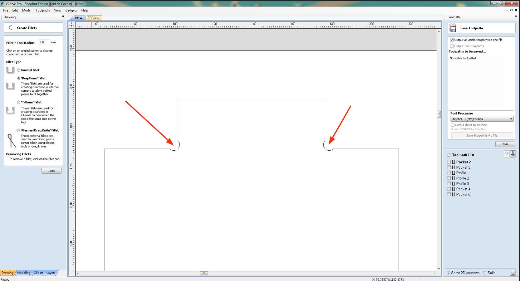
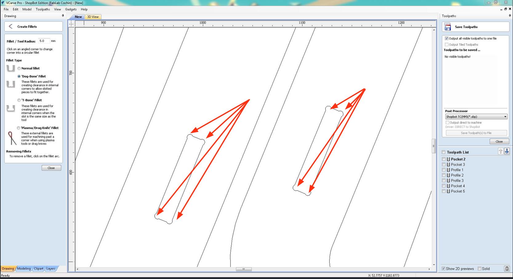
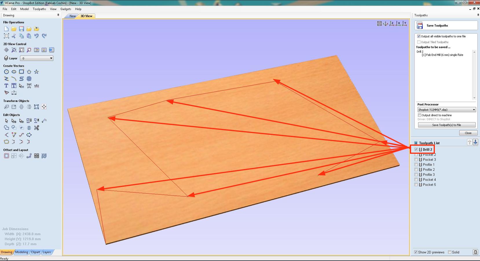
Now we use the Toolpath generation window located at the right of the screen. First, we use drill operation which makes holes for screws to be placed and simulate in 3D view to check if it is correct.
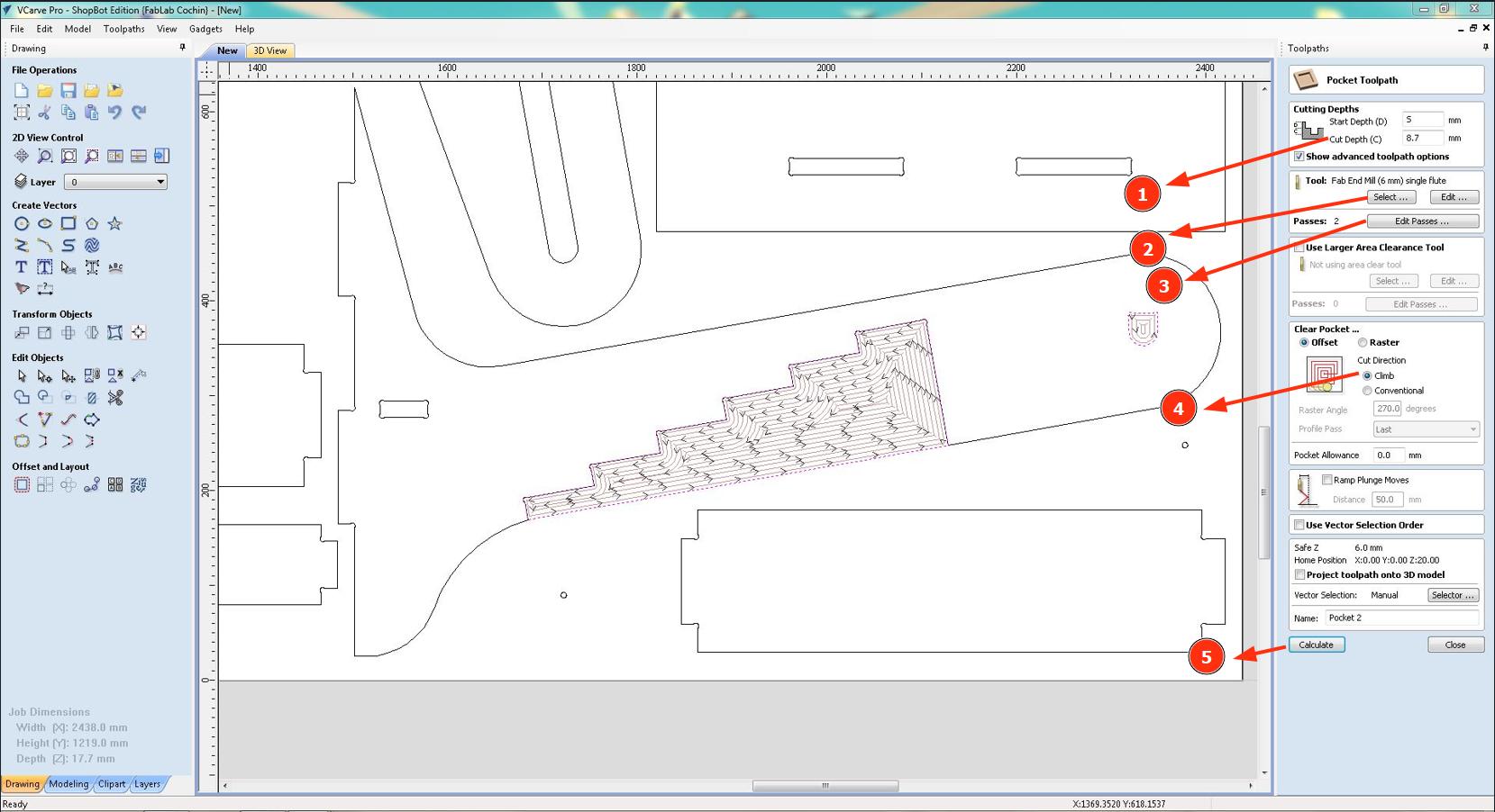
Then we set up the first Pocket operation. First, we select the inner features, select Pocket toolpath, specify 1.Cutting depths, 2. Tool, 3. Passes, 4. Cut direction and click 5. Calculate to generate the tool path.
For the Profile operation, we select the outer edges, select Profile operation, specify 1. Cut depths, 2. Tool, 3. Compensation left or right and 4. Create tabs, and click to generate the toolpath
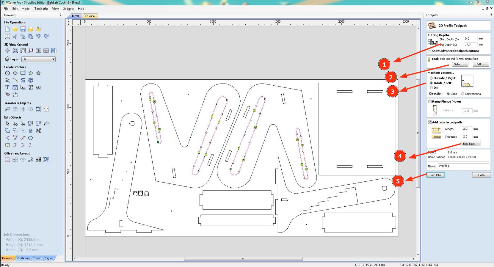
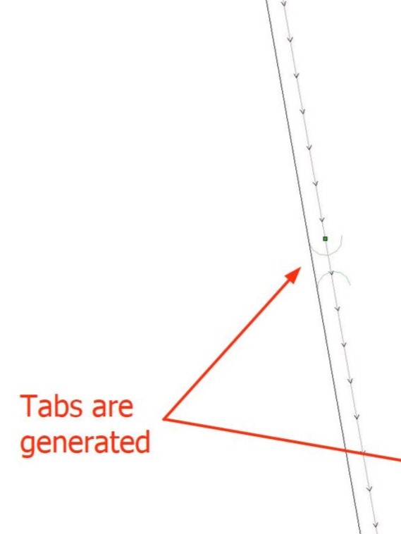
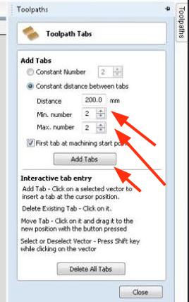
We repeat the steps for all the other operations
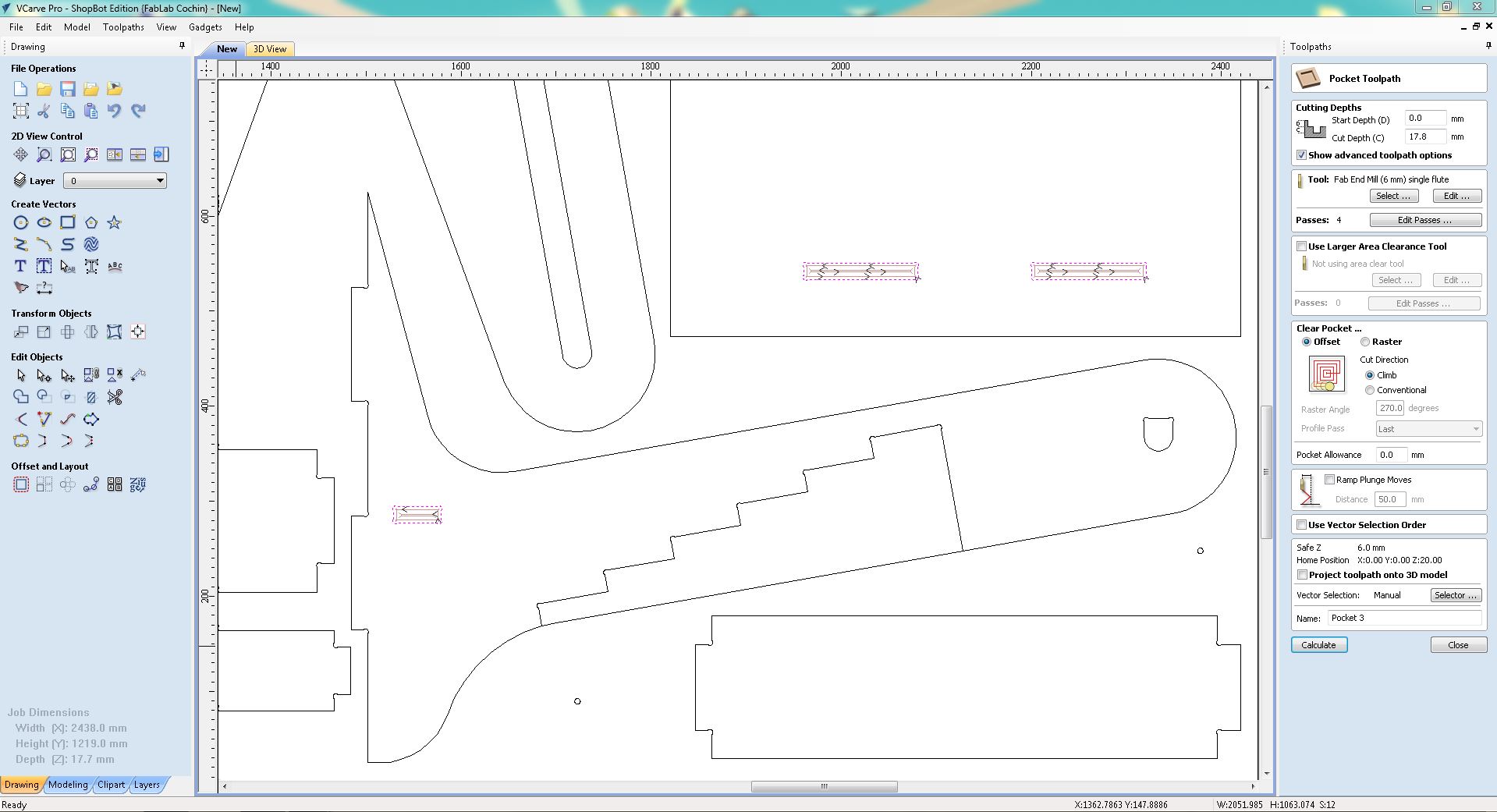
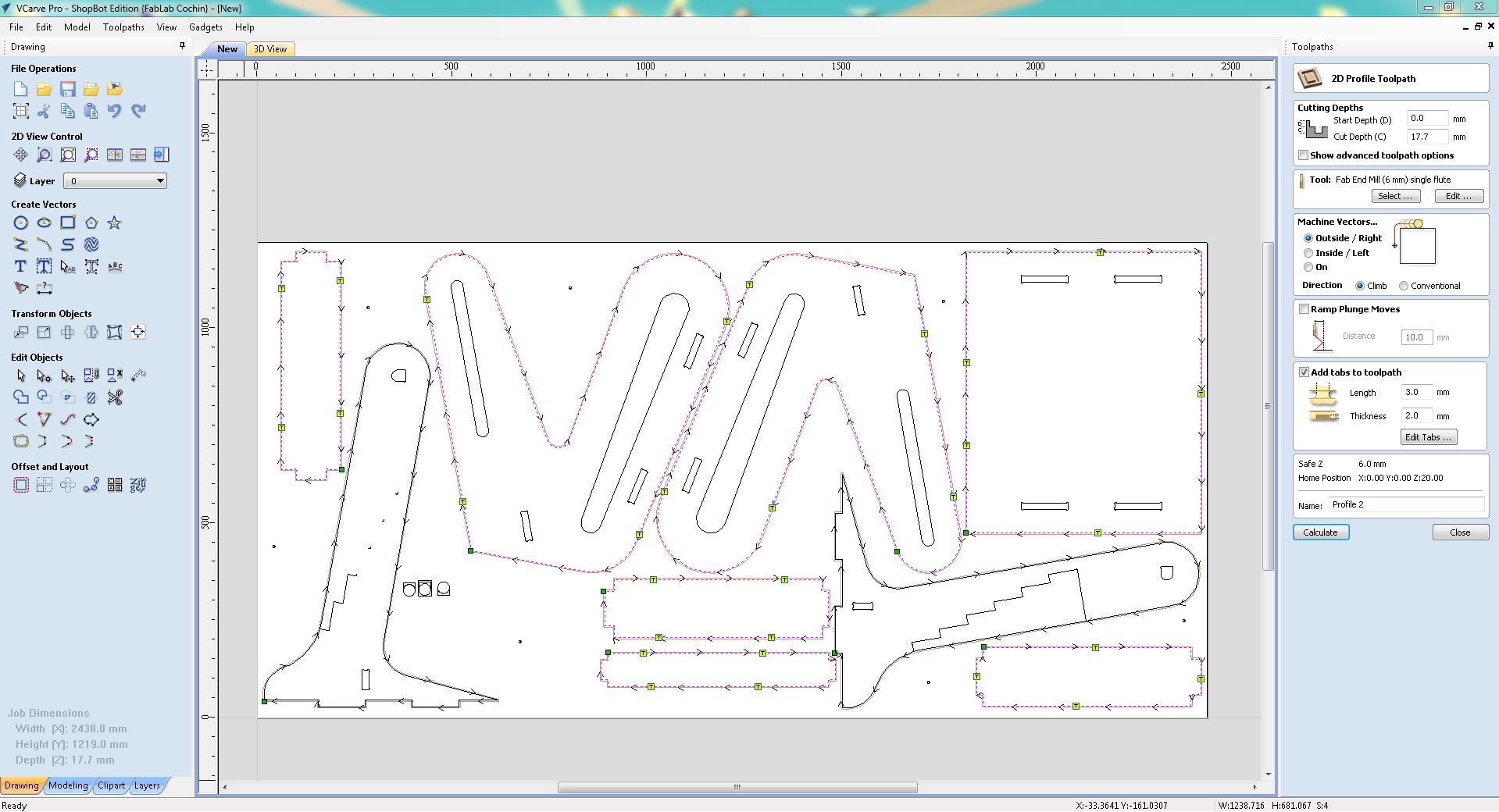
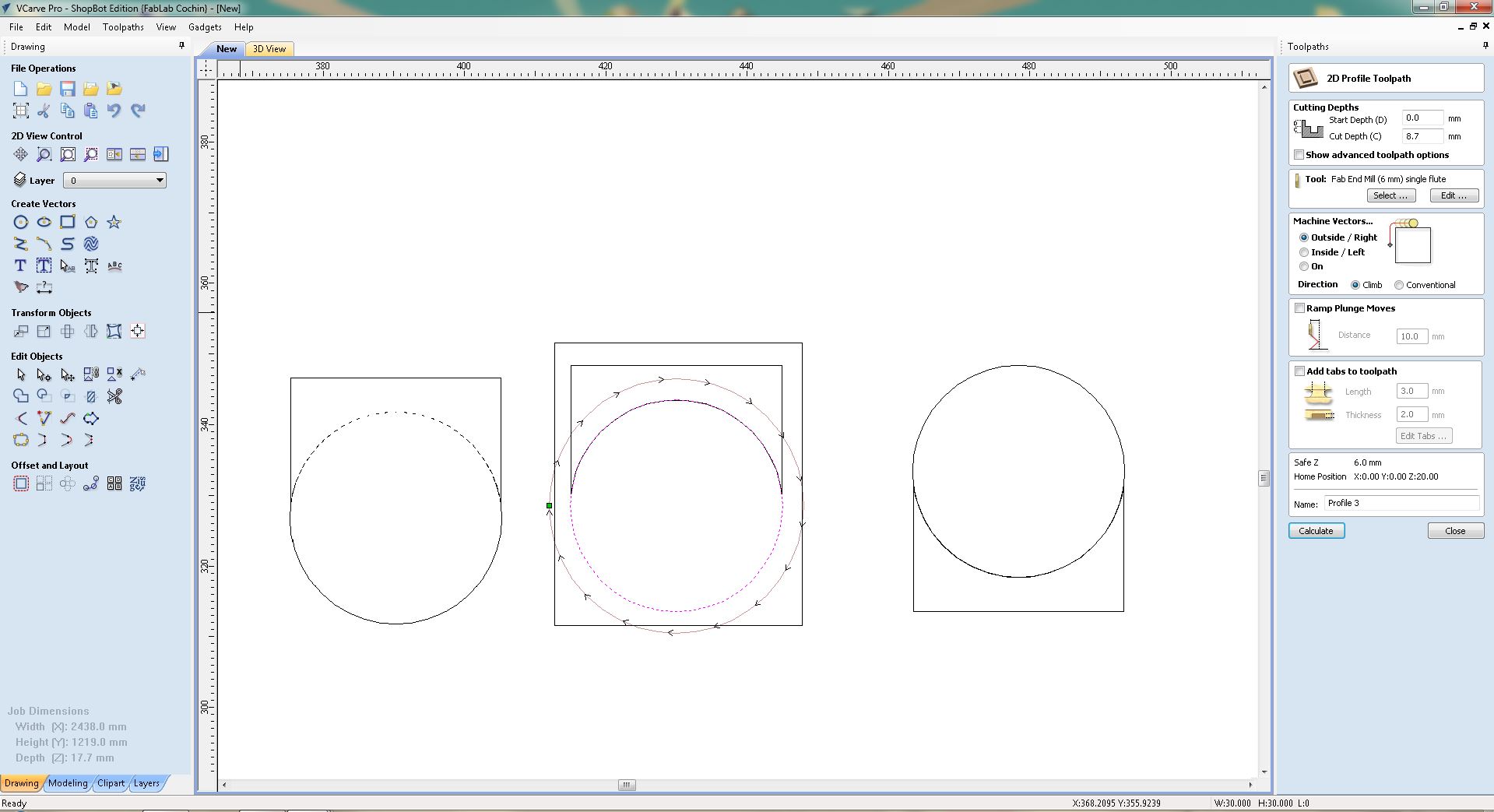
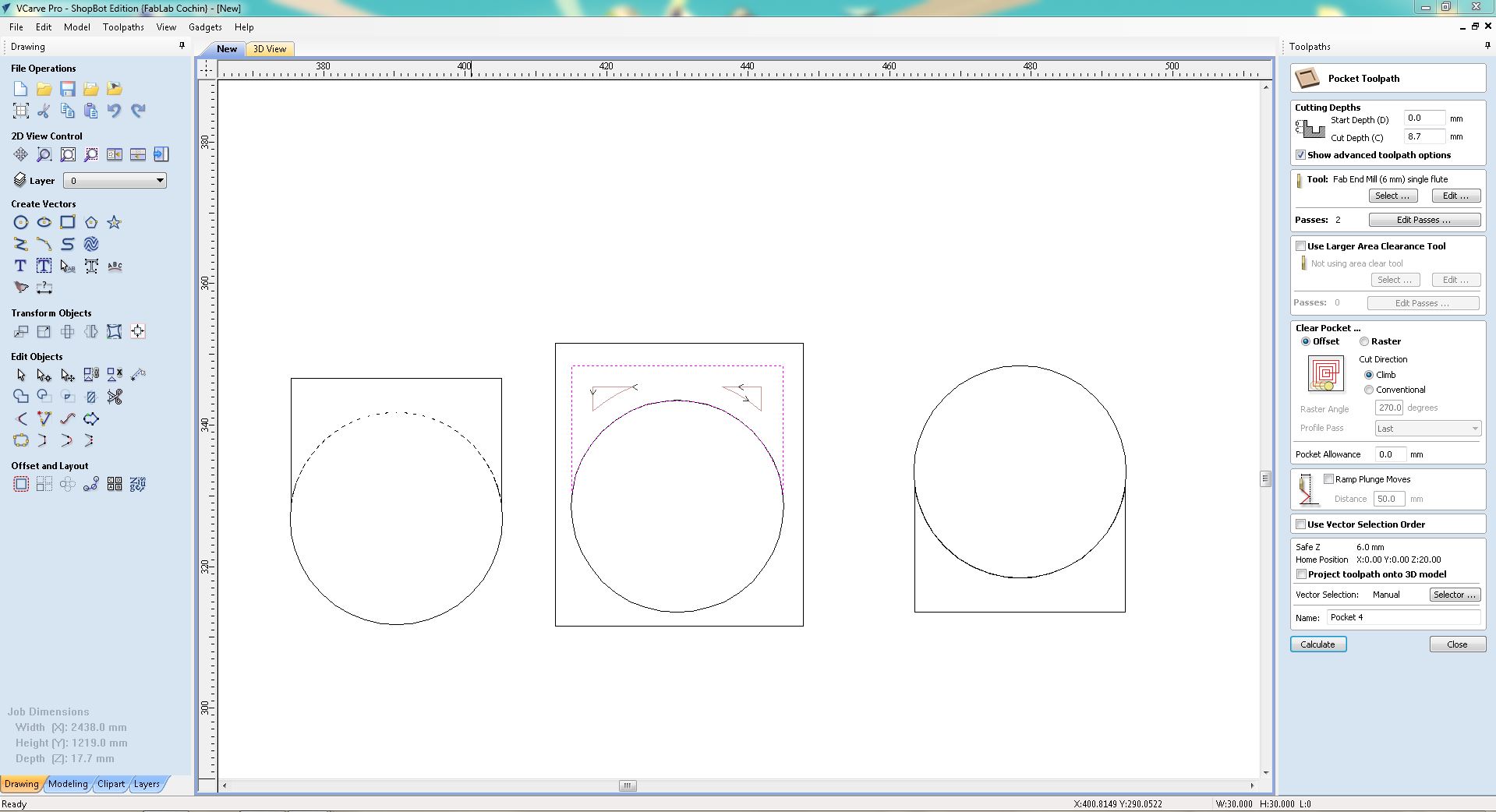
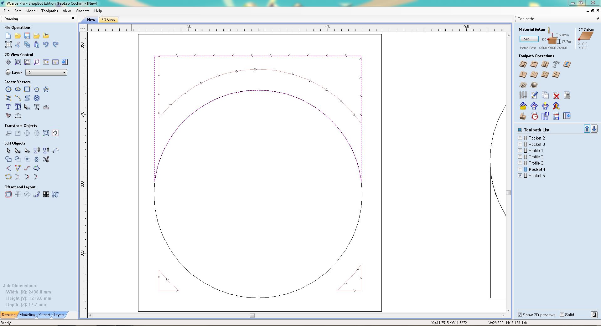
Once done, we verify all the operations in 3D view and export the drill operation and all the other operations as .sbp files
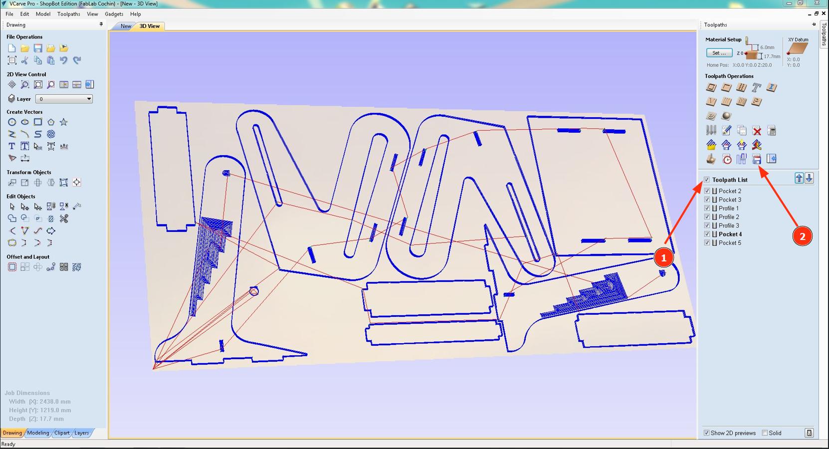
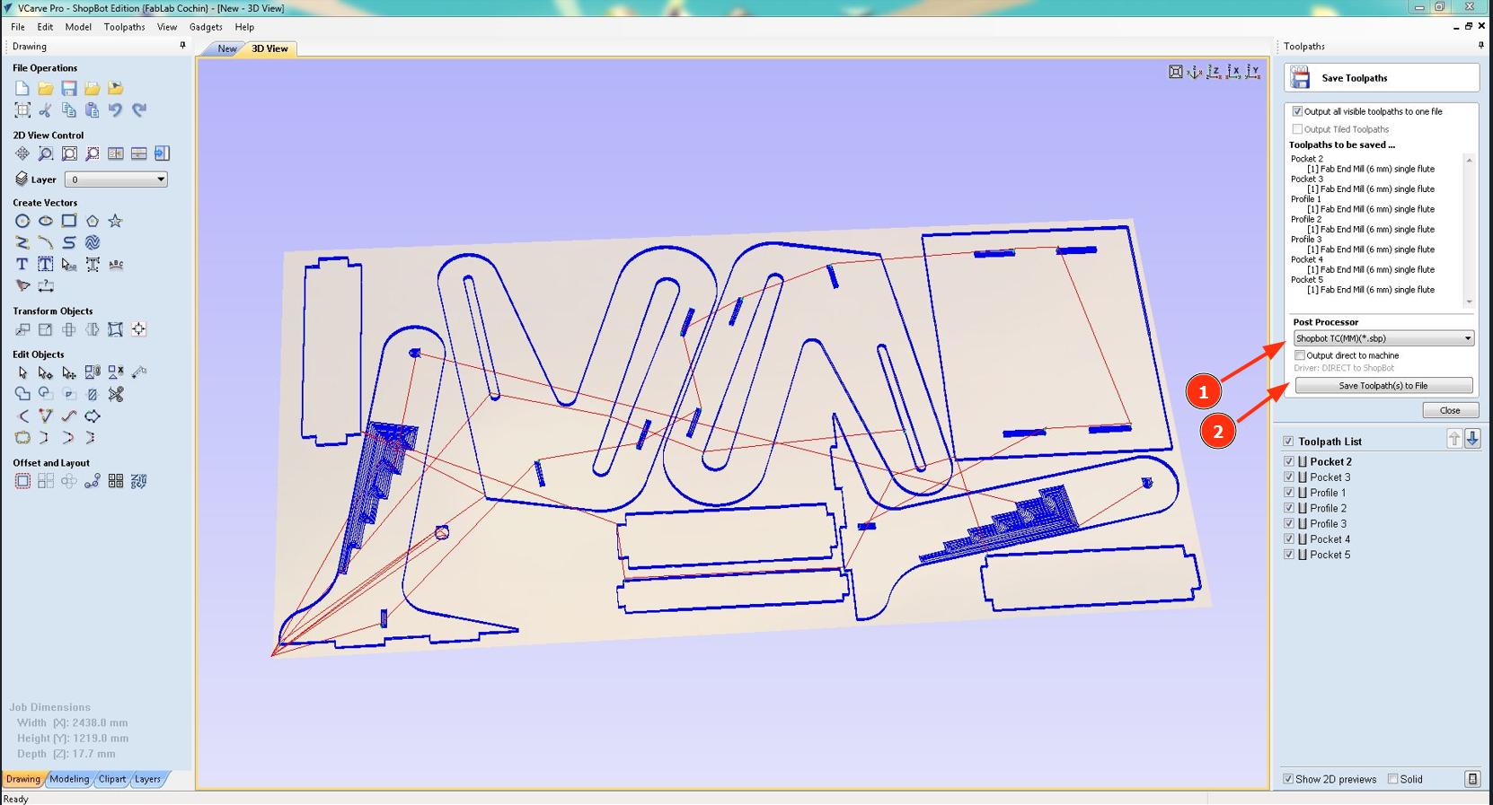
Setting Up
Now I load the workpiece onto the machine. Then I clamp the workpieces onto the bed with the help of clamps and screws at the edge of the bed (We had left a 20 mm frame width in Fusion)
Then I loaded the drill program into VCarve by usng the Cut Part option.
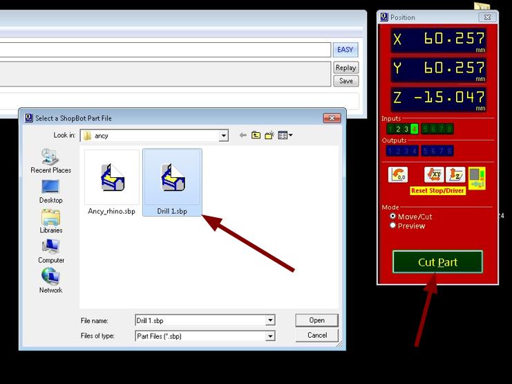
Then I clicked 'Start' and runed on the spindle by clicking 'Ok' in the dialogue box. Then we have to wait for a few seconds so that RPM of the spindle stabilises. Then I click 'Ok' and the machine starts routing the workpiece according to the design provided.
Then I drill screws into each of these holes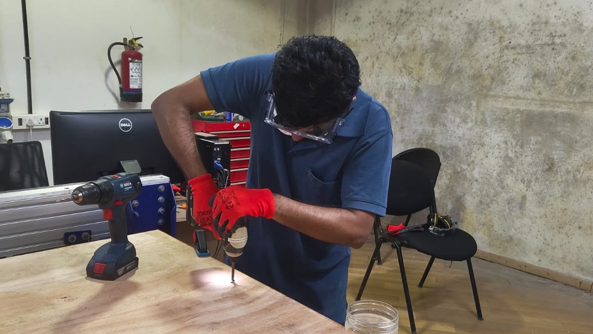
Then I moved the tool to one end of the machine and I took X and Y offset. For the Z offset we used a touchplate
Running the Toolpath
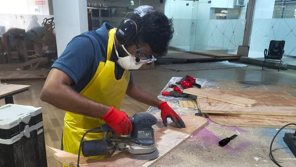
I follow the same steps that I used for drilling for cutting the design. Now I wait until the machine cuts all the pieces. It is important to wear all the required safety gear including gloves and safety goggles. Additionally, safety headphones are required since the machine will create a lot of noise while cutting
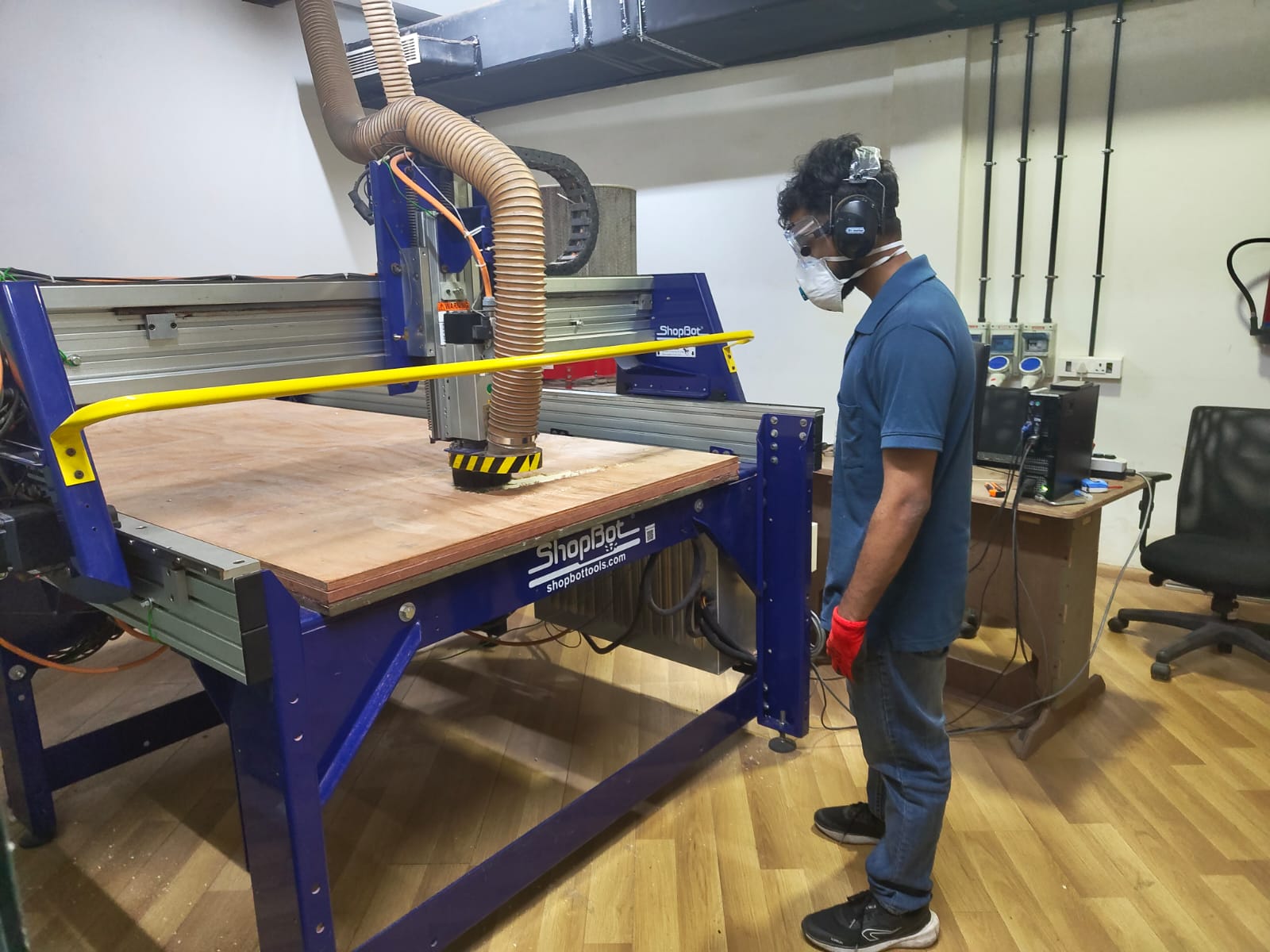
Post-processing
Once I cut all the pieces, the next step is to remove the cut pieces from the bed and perform some post processing.
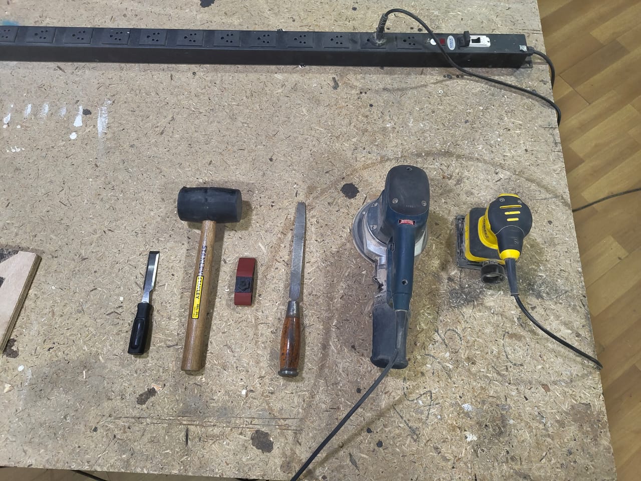
I use the chisel to remove bit of wood chips and tabs left behind, then I use the sanding machine to smooth out the surface and remove any burs at the edges. Then I use the file to sand the edges.
Assembling
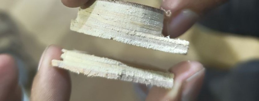
Since the pegs were so small, one of them snapped in half while machining. I then used glue to stick them
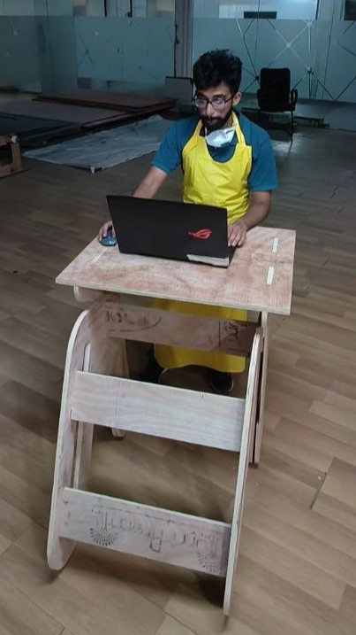
Then I need to assemble the pieces together using a Hammer. In places where I was not able to fit the plywood peices in the slots I made some chamfers using a chisel
Conclusion
This week I learnt to use CNC machining and CAM on the Shopbot to make simple furniture using plywood.