4. Embedded Programming
Objectives
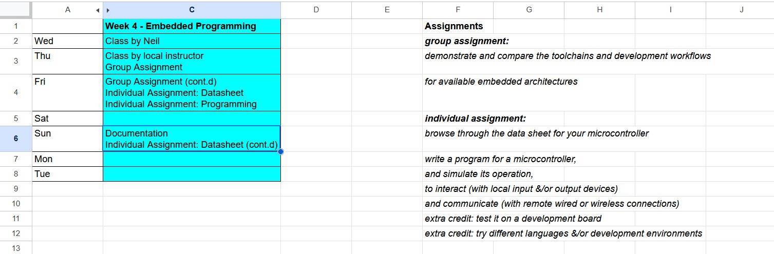
This week's assignment tasks are listed below:
- group assignment:
- demonstrate and compare the toolchains and development workflows for available embedded architectures
- individual assignment:
- browse through the data sheet for your microcontroller
- write a program for a microcontroller;
- and simulate its operation
- to interact (with local input &/or output devices)
- and communicate (with remote wired or wireless connections)
- extra credit: test it on a development board
- extra credit: try different languages &/or development environments
Timeline
Group Assignment
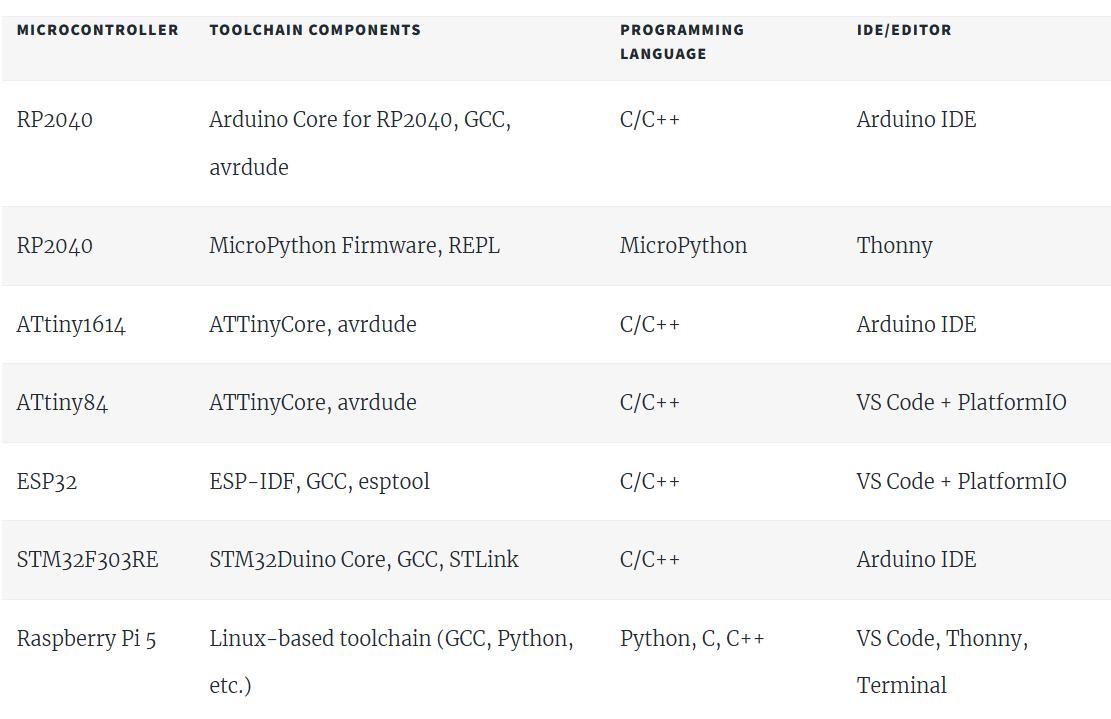
Comparing Toolchains and Development Workflows of Different Computer Architectures.
We learnt about different toolchains of different microcontrollers from different computer architectures. Along with that we compared our results to Rasberry Pi also, which is a full fledged computer rather than a microcontroller.
For more information, read our group assignment.
Individual Assignment
Browse through the Data Sheet for your Microcontroller
RP2040
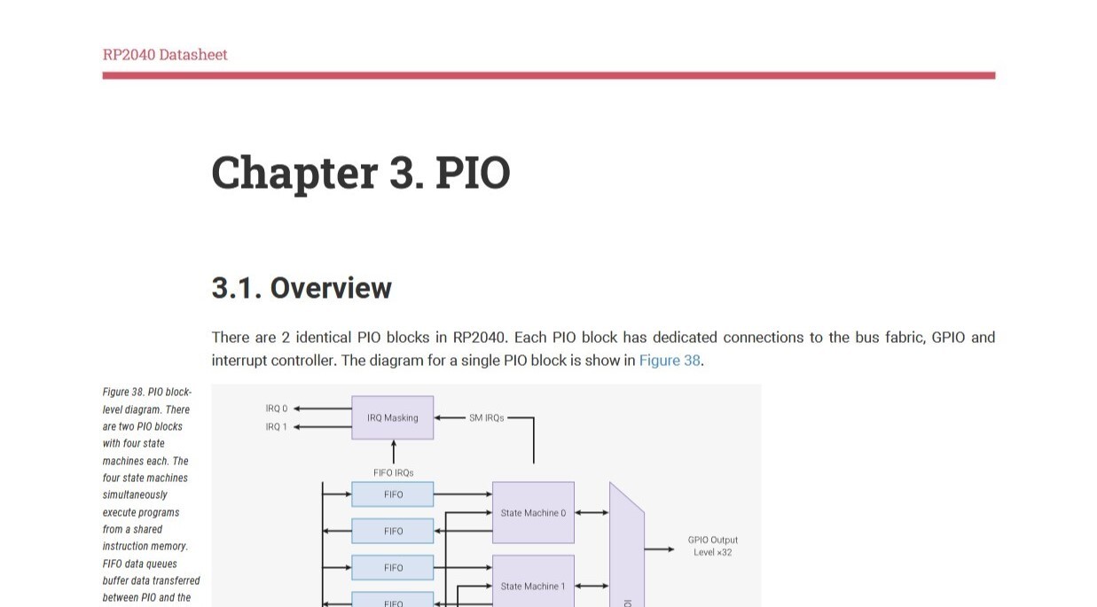
The official datasheet for the RP2040 has been linked here.

Name of the Chip: RP2040
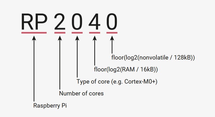
The chip is called RP2040. It is called so because
- RP: Made by Rasberry Pi Foundation
- 2: Has two processor cores Cortex M0+ processor cores. A core is an independent processor that is built into a CPU. Multiple cores mean that they can operate tasks independant of each other to avoid the heat vs performance issue.
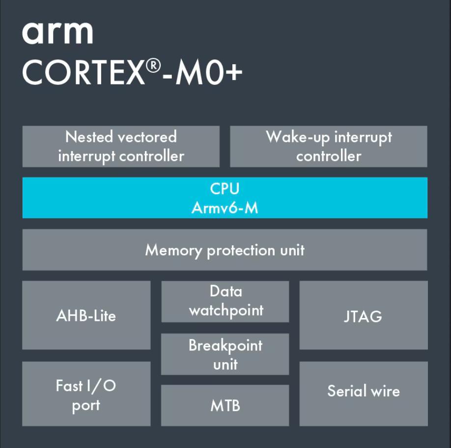
- 0: The cores are Cortex-M0+, which is based on the ARM CPU architecture, which is a family of RISC architectures.
-
4: The expression
floor(log2(RAM / 16KB)) = 4
because the chip has 264KB of RAM, and the floor function takes in a real numberXand outputs the nearest integer less than or equal toX. - 0: The number represents on-chip flash memory, which is memory that is stored in the chip even when the chip is powered off. Since the chip has no flash memory, it is represented with the number 0.
Speed: 133MHz
The dual cores can run upto 133 MHz. It has two phase-locked loops (PLLs) that provide a fixed 48MHz clock for USB or for Analog Digital Converter (ADC) , and a flexible system clock up to 133MHz for high power applications.
Memory: 264 kB SRAM & no onboard flash memory
The RP2040 has 264 kB of embedded Static Random Access Memory (SRAM; a type of volatile memory) for temporary memory storage and 0B for flash memory (permanent storage; a type of non-volatile memory)
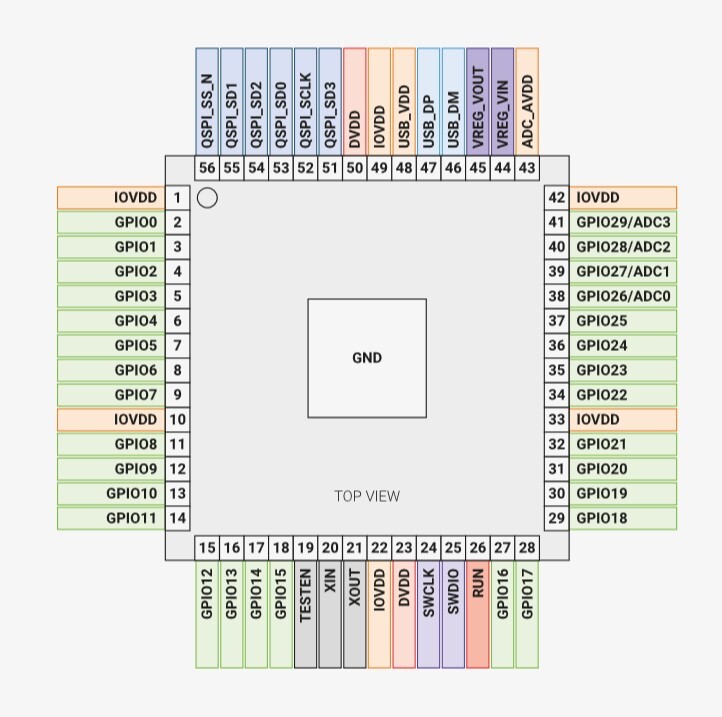
Pins: 36 GPIO Pins, out of which 30 are digital I/O Pins, which also include 4 Pins that can accept both digital and analogue input.
Among the GPIO pins, GPIO 0-25 accept accept digital inputs, whereas GPIO 26-29 can accept both analogue and digital signal input and output digital signals.
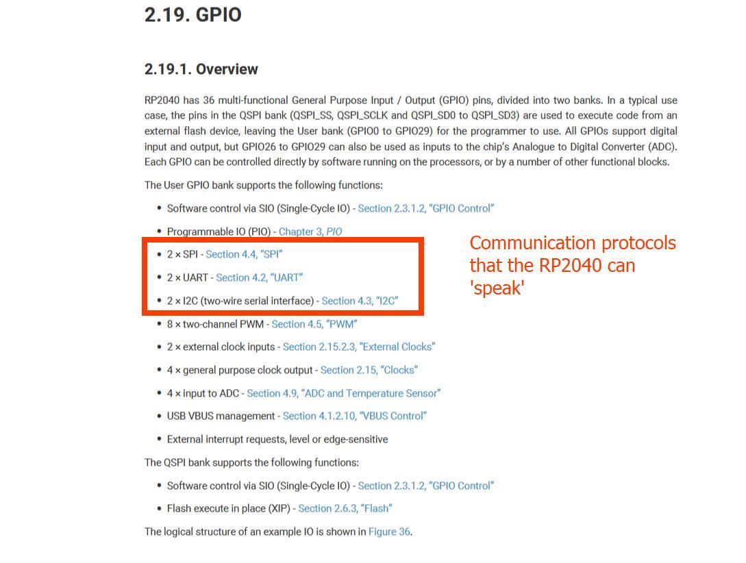
Communication protocols supported: UART, I2C, and SPI
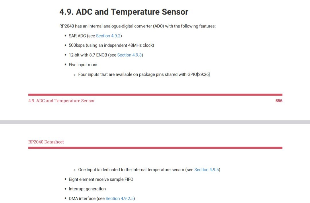
Analog to Digital Converter: The RP2040 has an internal ADC.
It has 5 inputs. 4 inputs are available on the pins shared with GPIO (GPIO 26-29), while one input is connected to an internal temperature sensor
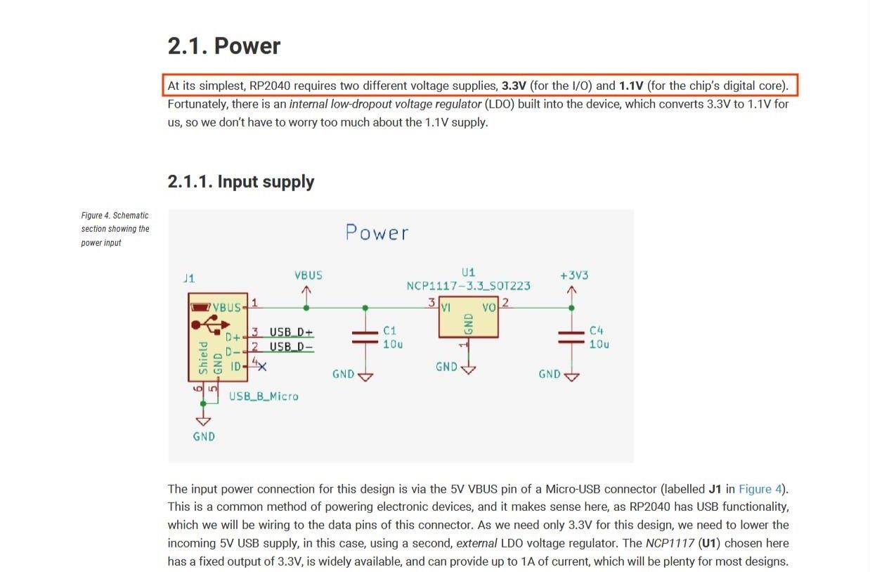
Operating and Logic Voltage: 1.8 to 3.3 V (preferrably 3.3 V)
Along with the previous datasheet, I refered another datasheet from Rasberry Pi called 'Hardware design with RP2040', which states that the RP240 requires 3.3V

Based on this Reddit post a logic voltage of x
means that the microcontroller will read a value equal to or close to x as 1 or digital HIGH and any value close to zero Volts as 0
or digital LOW. Hence the logic voltage of the RP2040 is also 3.3V
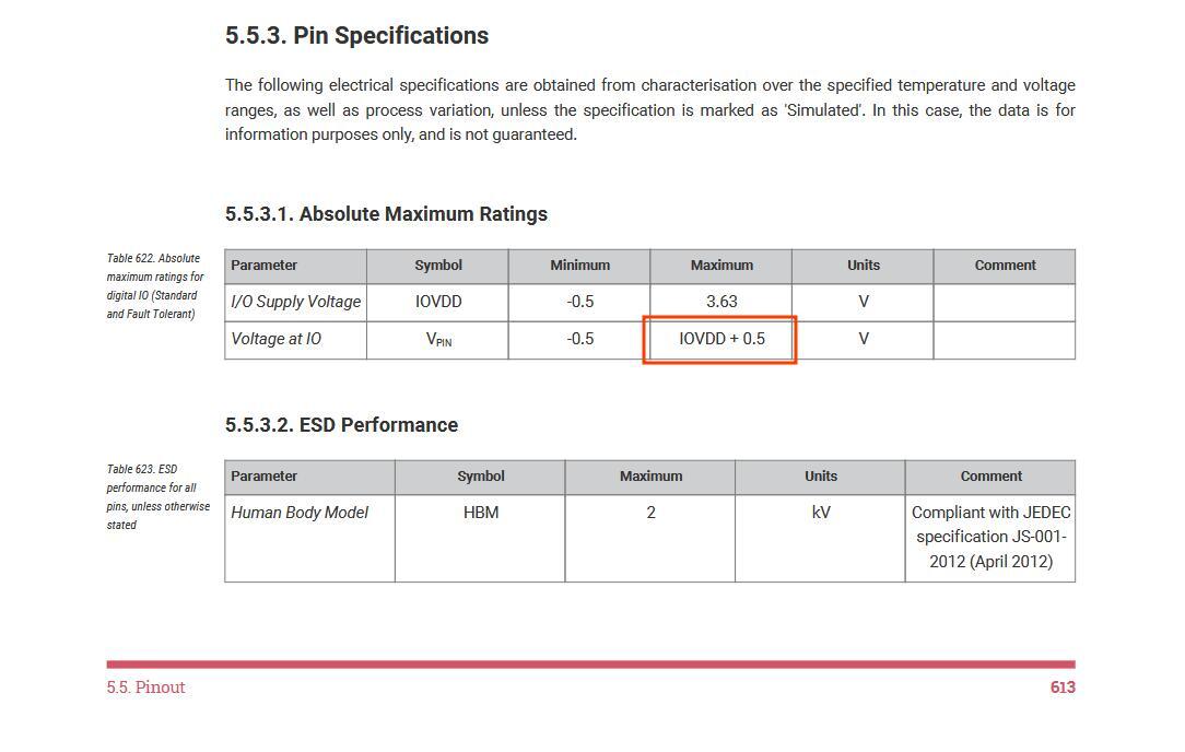
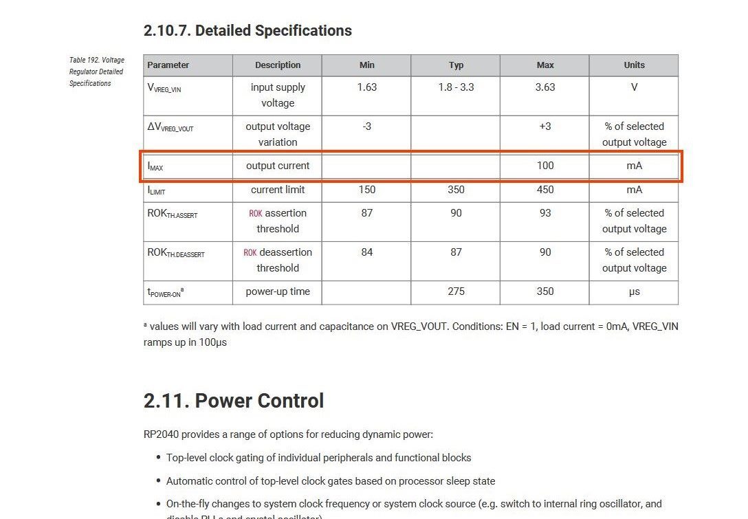
Maximum Tolerable Current and Voltage: 3.83V and 100 mA
STM32 Nucleo-64
Based on the databrief of the STM32 Nucleo-64 development board & the datasheet of the STM32C031C6 microcontroller.
- Language: Embedded C++
- Board: NUCLEO-C031C6
- Microcontroller: STM32C031C6T6
- Core: ARM Cortex M0+
- Speed: 48 MHz
- Flash:32 KB
- SRAM: 12 KB
- Operating voltage: 2-3.6V
- Pins: 48 pins
- Communication interfaces: I2C (PB6/PB7), USART (PA9/PA10), SPI
- Development support: SWD (SWCLK-PA13(Pin 35), SWDIO-PA14(Pin 36), Power-VSS/VDD(Pin 6/7), GND-VREF(Pin 5))
- ADC: 12 bit internal ADC
- Development toolchains: Arduino IDE with SWD programming tool (ST-LINK/V2)
ESP32 S3
Based on the datasheet for ESP32S3
- Language: Embedded C++
- Board: ESP32-S3 (e.g., ESP32-S3-DevKitC-1)
- Microcontroller: ESP32-S3
- Core: Dual-core Xtensa® LX7 32-bit (240 MHz max)
- Speed: Up to 240 MHz
- Flash: 512 KB internal + external SPI Flash (up to 8 MB supported)
- SRAM: 512 KB internal SRAM + up to 8 MB external PSRAM
- Operating voltage: 3.0–3.6V (typically 3.3V)
- Pins: 45 GPIOs (up to 34 usable depending on flash/PSRAM configuration)
- Communication interfaces:
- I2C (2 × I2C interfaces)
- UART (3 × UART interfaces)
- SPI (4 × SPI interfaces)
- I2S, USB 2.0 OTG, SDIO, CAN (TWAI®), RMT
- Development support: USB Serial/JTAG or SWD (JTAG: MTCK/MTDO/MTDI/MTMS)
- ADC: 2 × 12-bit SAR ADCs (up to 20 channels)
- Development toolchains: ESP-IDF, Arduino IDE, PlatformIO (via USB or UART bootloader, optional JTAG)
Writing a Program for your Microcontroller
Some Definitions
I have listed some definitions for some terms used in programming
- Function: A block of code that performs a specific task and reused at different parts of the code, eg:
sleepin Micropython - Class: A 'blueprint' for creating objects, eg:
Pinin Micropython - Object: A specific implementation of the class, with variables containing data specific to that object
- Module: A file containing multiple Python functions, classes, and variables. eg:
machine - Loop: A block of code that keeps being repeated over and over until a certain condition is met. In cases where no condition is added then you get an infinite loop. eg:
While True:,void loop()
Program 1: Controlling an LED using a Button using a Rasberry Pi Pico
- Language: Micropython
- Microcontroller: RP2040
- Board: Rasberry Pi Pico
- Environment: Wokwi (simulation)
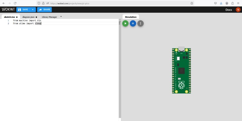
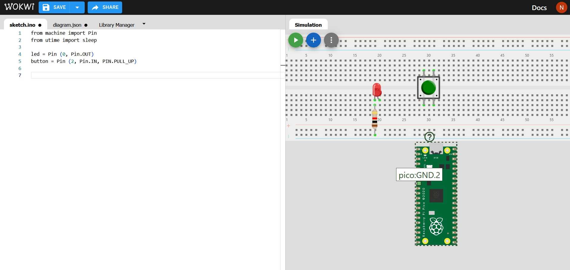
Once I learnt the basic syntax with the help of examples from our instructors, I wrote a simple piece of code written in Mycropython using a Rasberry Pico development board (includes RP2040 chip) to control the LED using a button, using an example Blink program
First we import the required modules. Because we only need to import specific objects, ie. 'Pin' class from 'machine' & 'sleep' function from 'time' we only import using the commmand: from x import y
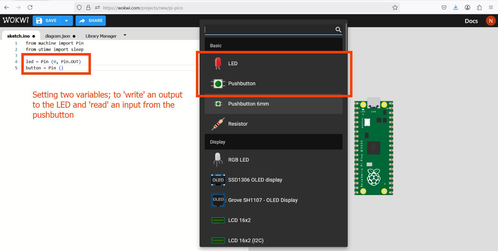
Then we name a variable led where we state that Pin 0 wil be an OUTPUT Pin, meaning an voltage will be sent to it, which will be used to light up the LED.
We also name a second variable named button which is connected to pin 2 on the Rasberry Pi Pico. We set it as an INPUT pin, meaning it will take voltage readings from the push button. Additionally, using the PIN.PULL_UP method, we set pin to a default 'HIGH' state until the button is pressed.
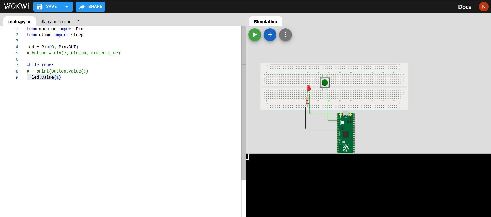
To make neat connections I used a breadboard, added the components to make an electrical circuit. The following image shows how they are connected internally
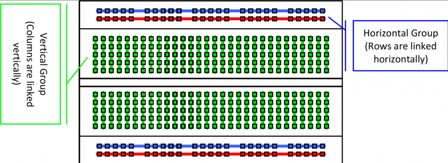
I have previously tinkered with simple circuits in the past so I knew how to connect simple devices like LEDs and switch buttons. Since an LED is a diode, it cannot be connected in any manner. The Anode (A) is the bent end that should be connected to the digital I/O pins and the Cathode (C) should be connected to the ground (GND) pin. Also, a 1K resistor should be connected in series with the LED to stop it from drawing too much current.
Once I have placed all the components, I then connect all the devices using wires. You can see which are the GND pins by hovering on top of the board.
I added a While True:statement to add a loop that goes on infinitely
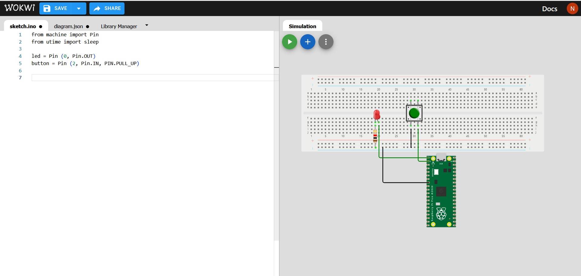
Make sure to check the file type! When testing the Micropython script will not work in a sketch.ino file. It should be a main.py file
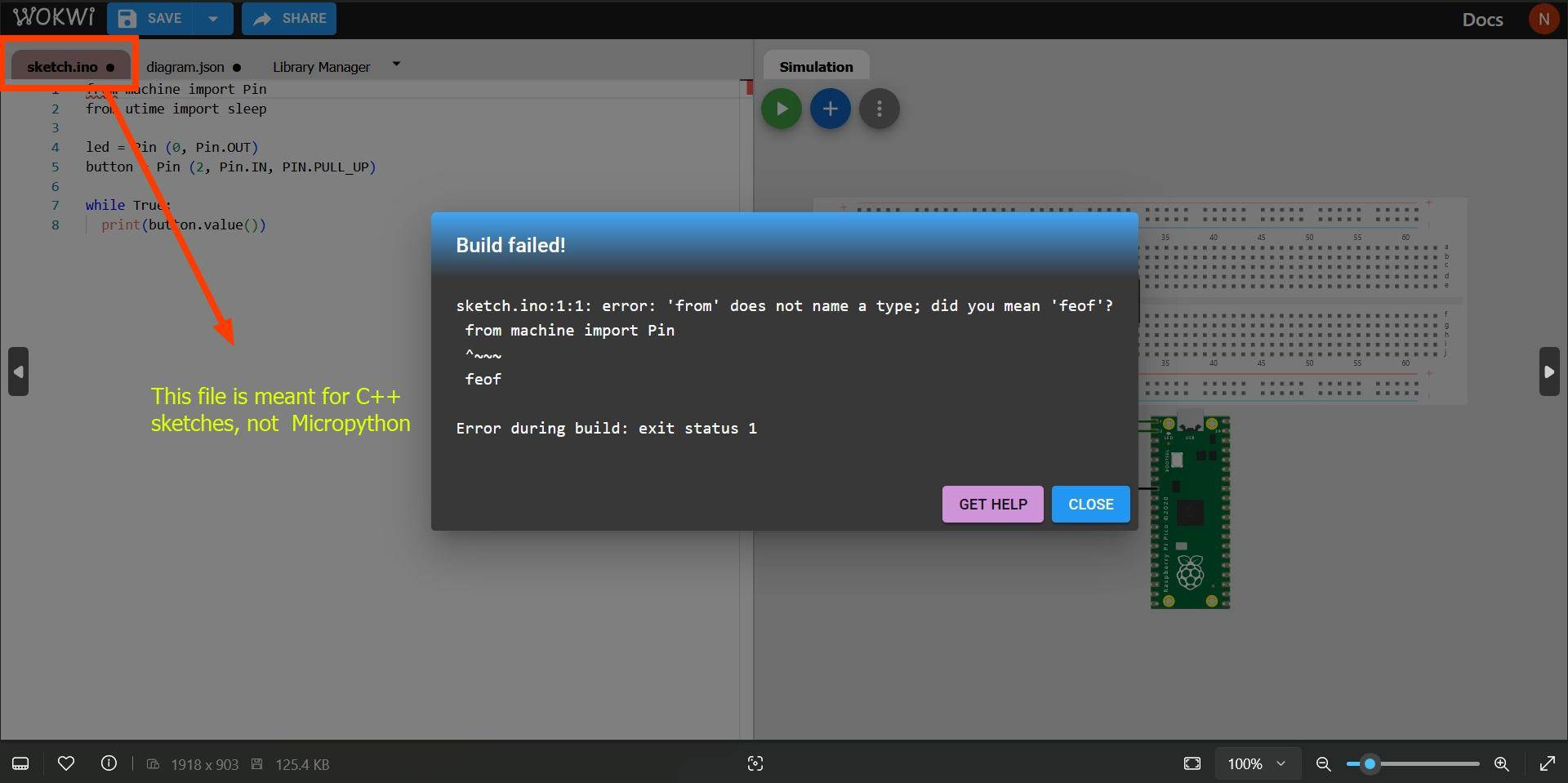
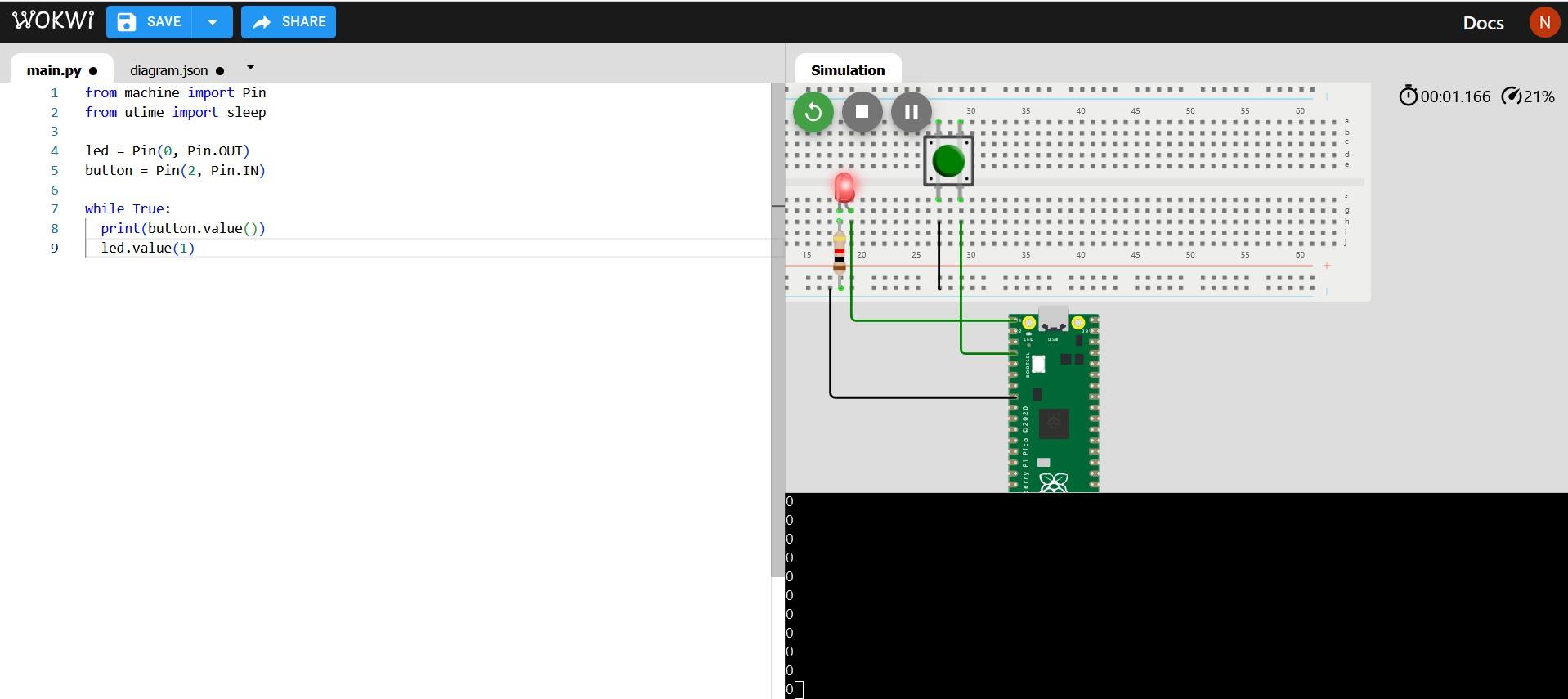
To test the button values, I added a Serial output using the command print(button.value()). But when running, nothing showed up on the console. I tried commenting different parts of the code to see if an LED lights up using the command led.value(1) but it did not work
To comment code, I use the shortcut Ctrl+/
In situations like this, I take a break and come back to the problem with a fresh mind.
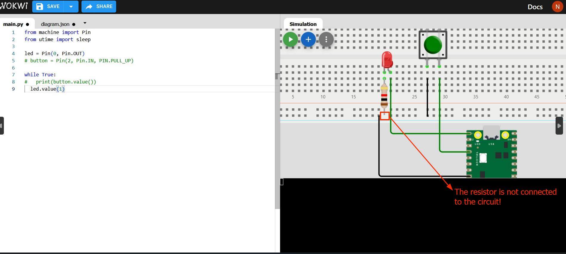
And it worked! I realized my error was that I did not connect my resistor to the circuit.Once I changed this, the code started working and the LED starting lighting up
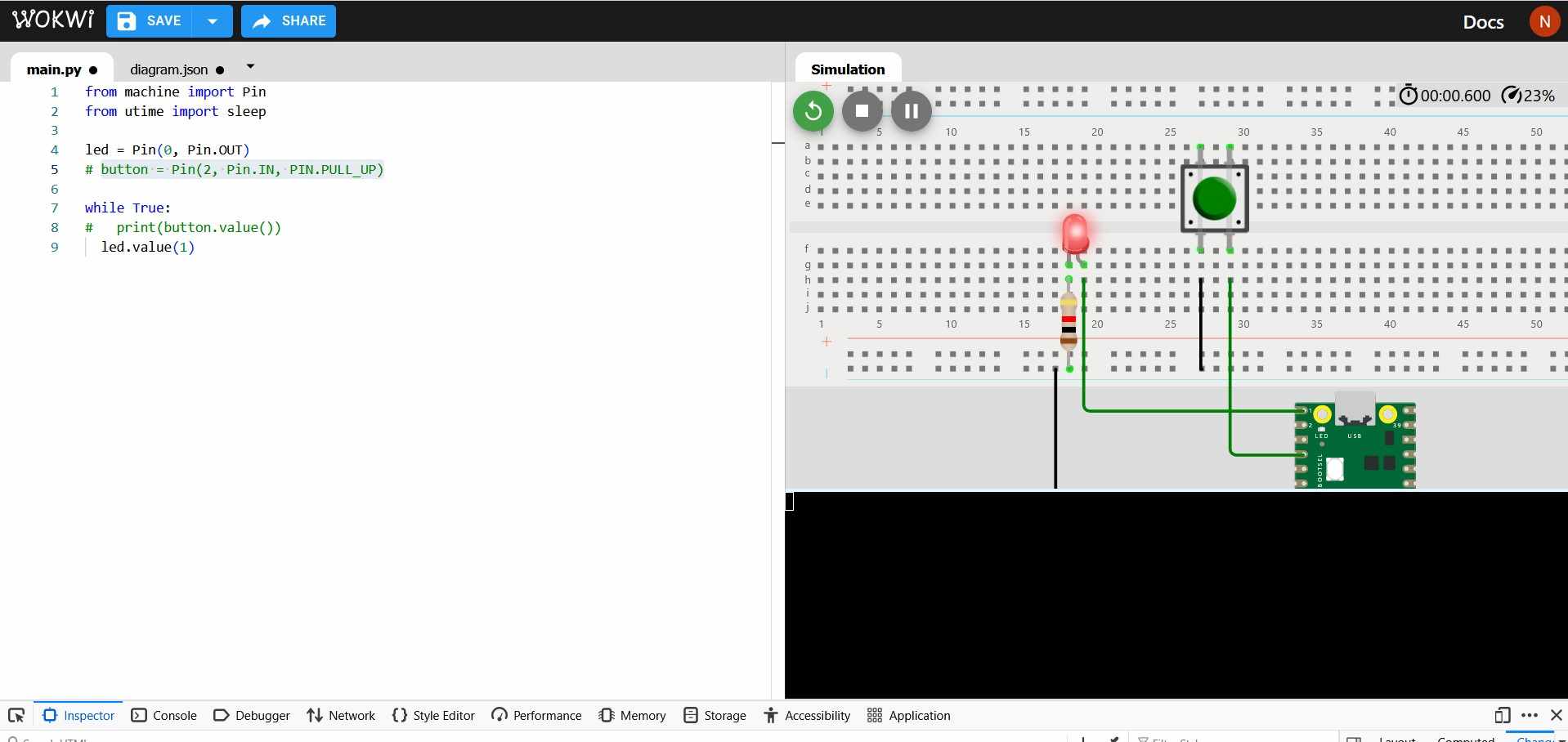
But when I uncommented all the code lines, the code again did not work.
I decided to use the commenting approach again to understand where the problem was, and found out it was a problem with the statement about declaring the variable button
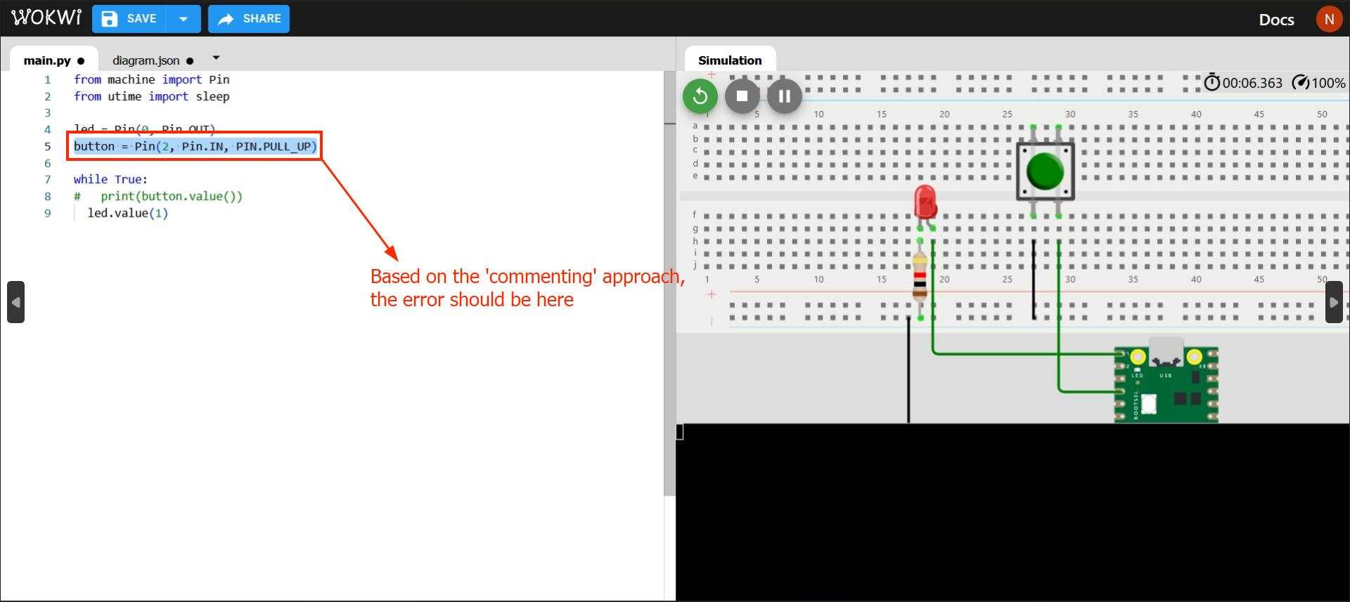
I knew it was a problem with the PIN.PULL_UP command since it was the code was running without it, even though you would then run into issues with sreading the correct button state due to the problem with floating values
I then realized that I used the wrong syntax PIN instead of Pin while writing the command Pin.PULL_UP.
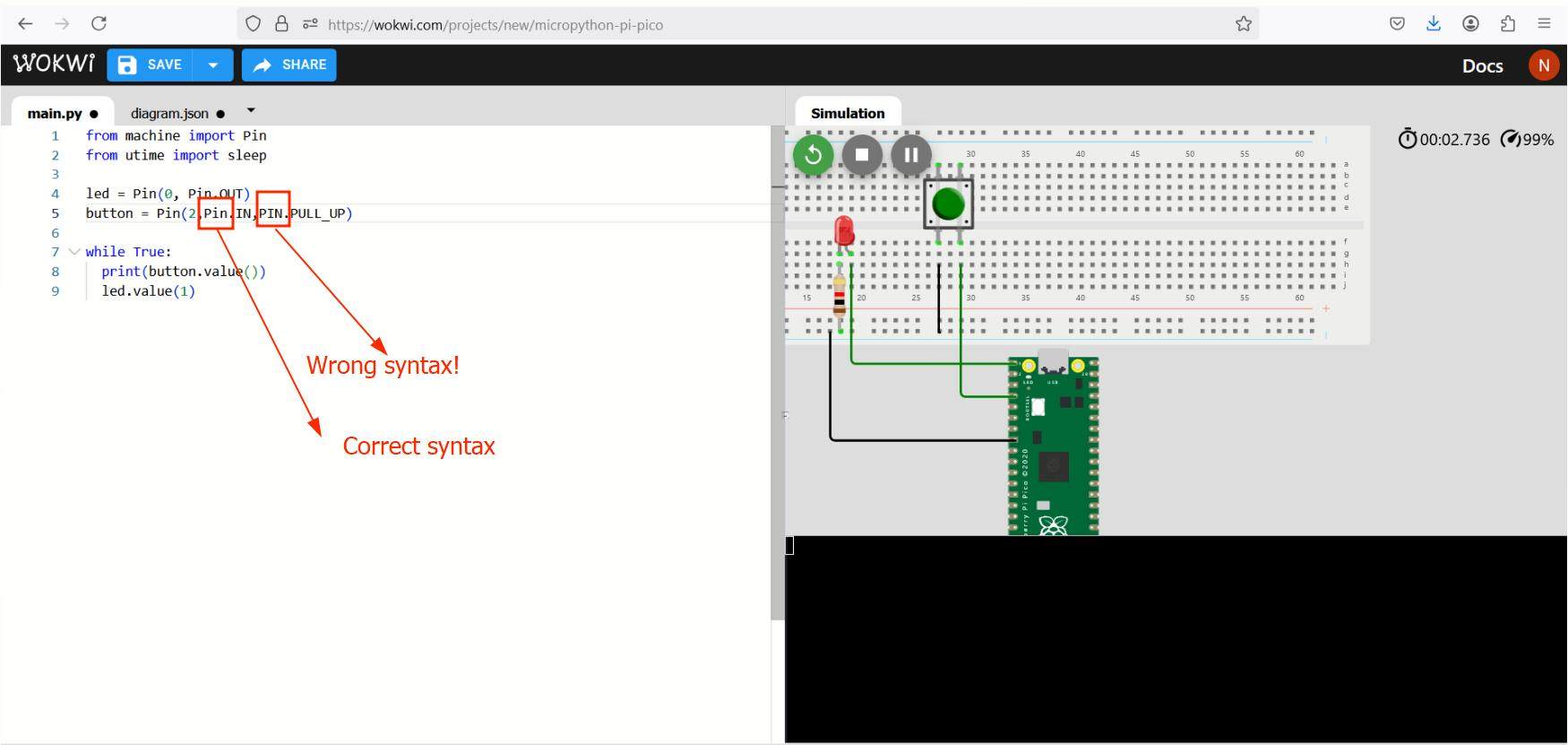
Once I corrected it, the code is now running
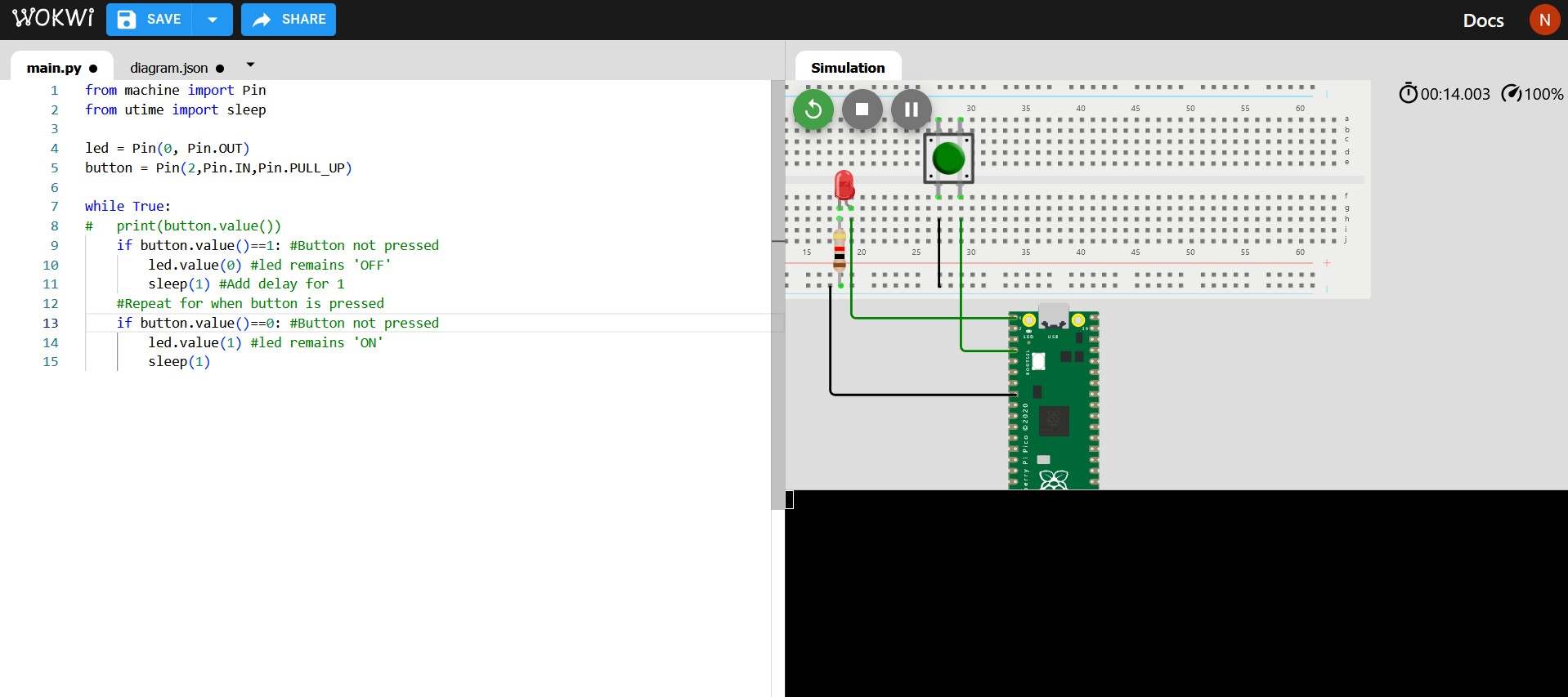
Inside the While Trueloop I added an if statement stating that if the button value is 0 (the 'ON' state) using the if button.value()==0. The == operator means to see if 'check if x = y'. If it satisfies that condition, it then goes inside the if code block and switches on the LED using the command led.value()=1.We then add a delay of 1 second using the sleep(1)command. We then repeat the same process for when the button is OFF
But the code did not work again
With the help of my instructor, the error was resolved when the indentation was corrected
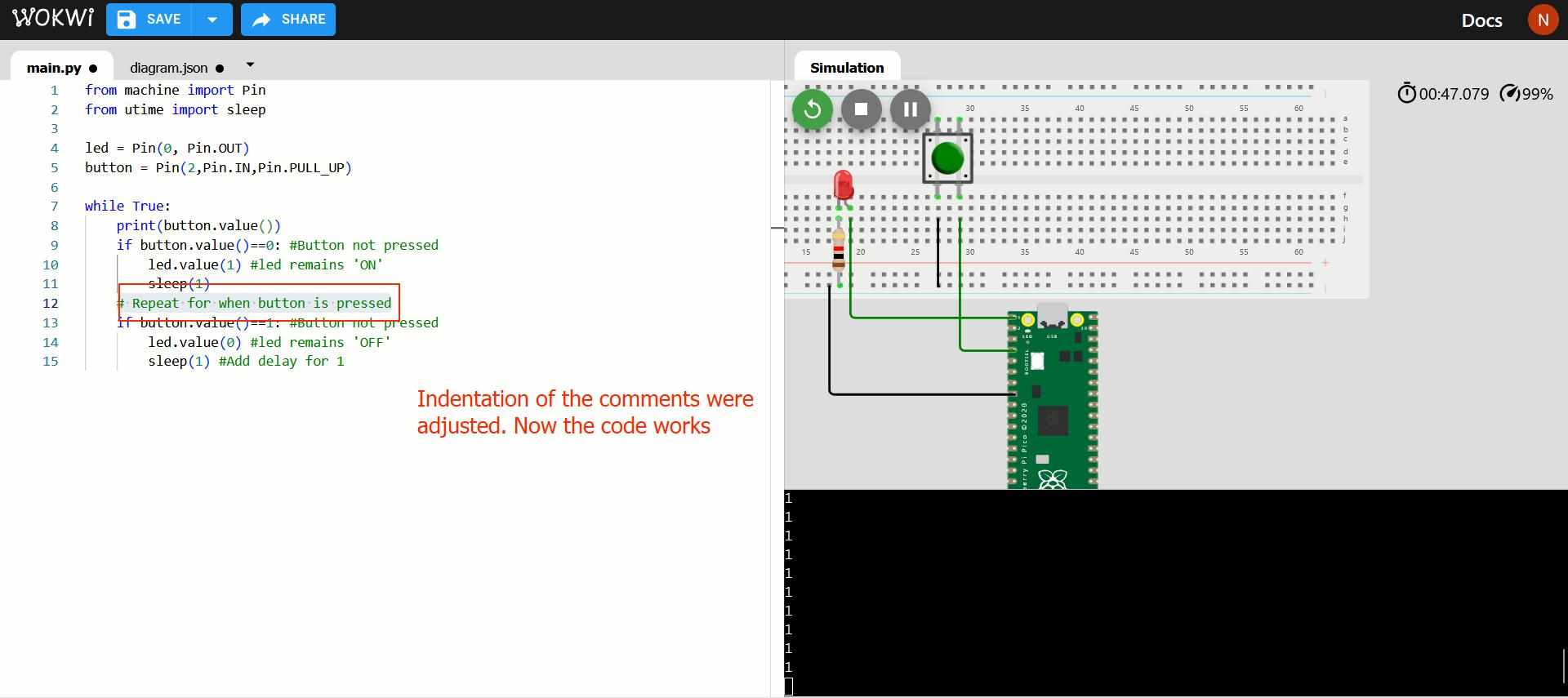 The code is now running.
I now added a Serial Output using the print command to state when the LED is on and when it is OFF and commented the print(button.value())
As long as the button is pressed, the LED will remain ON and a message confirming the same will be displayed in the terminal. When the button is not pressed,
the LED remains OFF which is also confirmed by another message in the terminal.
The following is the code I wrote. Comments have been added by adding '#' to enhance readability':
                                #importing required modules and objects
                                from machine import Pin
                                from utime import sleep

                                #defining variables
                                led = Pin(0, Pin.OUT)
                                button = Pin(2,Pin.IN,Pin.PULL_UP)

                                while True:  #creating an infinite loop

                                    # print(button.value()) #uncomment for debugging

                                    #If condition when button is not pressed
                                    if button.value()==0:
                                        led.value(1) #led remains 'ON'
                                        print ("LED is ON")
                                        sleep(1) #sleep for 1 second

                                    #If condition when button is pressed
                                    if button.value()==1: #Button not pressed
                                        led.value(0) #led remains 'OFF'
                                        print ("LED is OFF")
                                        sleep(1) #Add delay for 1
Program 2: LED Blink using a PIO in the Rasberry Pi Pico
- Language: Micropython
- Microcontroller: RP2040
- Board: Rasberry Pi Pico
- Environment: Wokwi (simulation)
A PIO (Programmable Input/Output) is a programmable piece of hardware that can be customized to perform high speed but non-complex programming tasks in the background independant of the cores, which means the main processor core is free to take on more tasks that take more computing power.
They are especially useful for communicating with serial devices with no hardware support, for pulse width modulation, etc. To know more check this web article that provides an overview of what a PIO is and its potential usefullness.
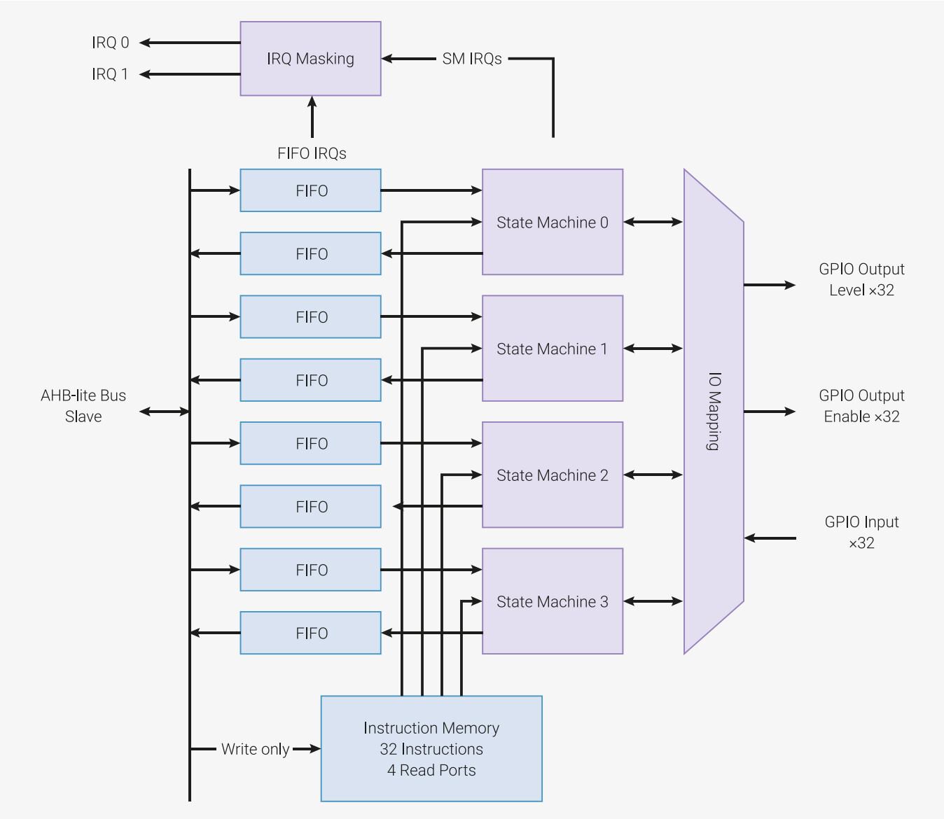
The RP2040 has two identical PIOs, each containing 4 state machines that share memory, ie. you can send 32 'words' or instructions to it a time.
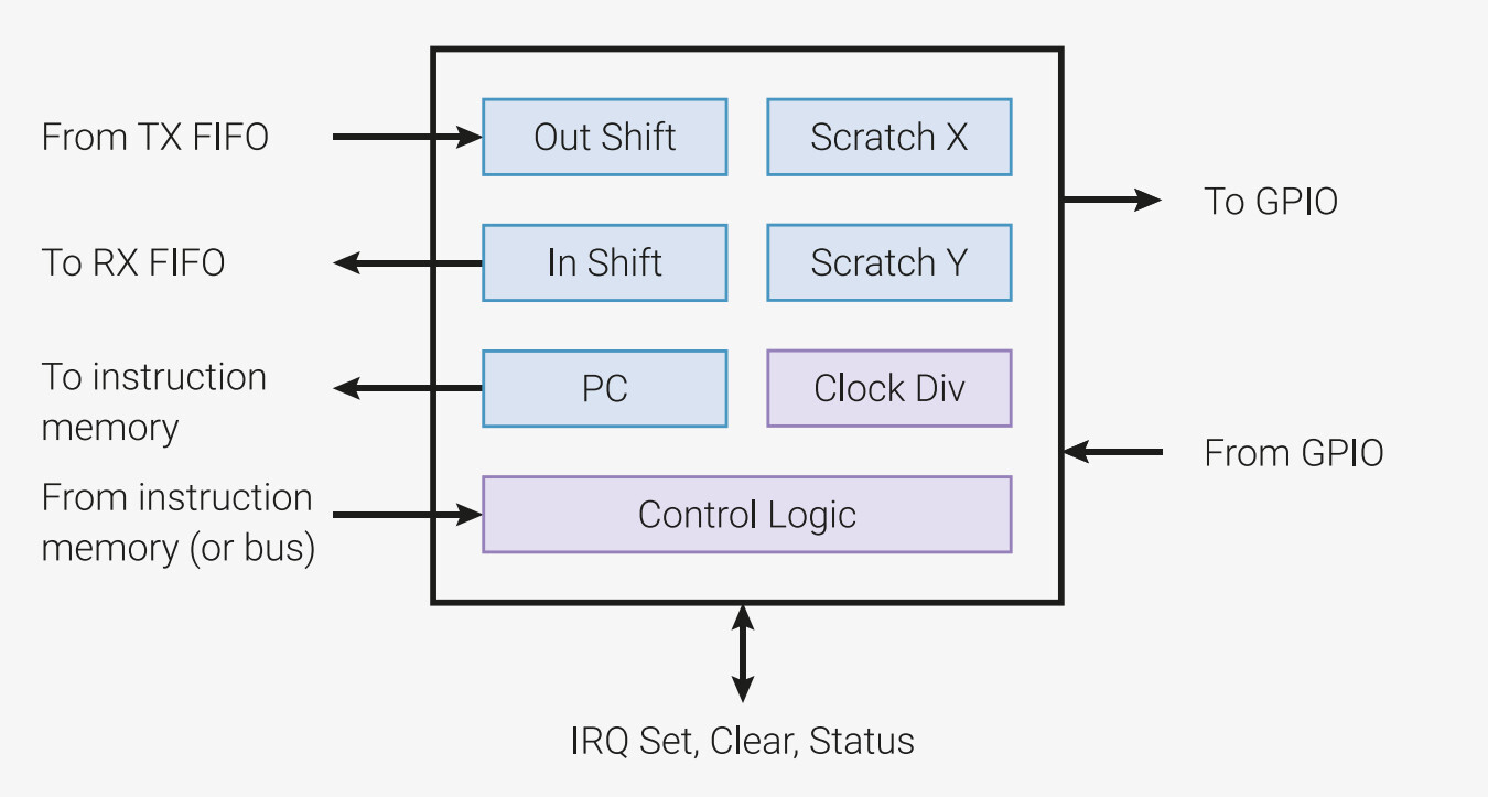
- Output Shift Register (OSR): Holds data before sending the data via FIFO or pins.
- Inputs shift register:Stores incoming data before sending it FIFO
- X & Y register: General-purpose registers. A single general purpose register (X only) may be limiting, in which case we usa an additional Y register.
State Machine: An automatic system that follows certain rules to transition between different states. They can work independantly without needing constant instructions from the main processor, so they use very little processing power. Also they run very fast, which is very useful in communicating to different hardware device. Each state corresponds to a specific instruction that is being executed.
Each state machine has four types of registers
FIFO: It stands for First In, First Out. It is a type of buffer(ie. temporary memory storage) that is capable of transfering data between the CPU and a state machine. Each state machine has a TX (Transmitter) FIFO (to sen) and an RX (receiver) FIFO to (to receive dazta)
IO Mapping: This refers to how the physical pins are assigned to the state machines Each state machines can control 32 of the RP2040 GPIO pins, but not all of them they are physically mapped to the Pico.
Instruction Memory: Since the PIO runs independantly from the CPU, it requires its own memory to store the program.The instruction memory refers to the memory that all 4 of the state machines can access. It can store 32 instructions, where each instruction is 16 bytes(2 bits)
Programming: Each instruction is written in one clock cycle, ie., 32 instructions can be sent in 32 clock cycle. This frequency can be adjusted to adjust the clock cycle, like I have done in my program.
I used the Digikey tutorial to program using the PIO, along with referring to the RP2040 Datasheet and Raspberry Pi Pico-series Python SDK documentation for reference.


I also used ChatGPT to simplify the meanings of many of the technical terms that were being used in the tutorial and documentation.
Prompt 1: What is a PIO in RP2040
PIO (Programmable Input/Output) in the RP2040 microcontroller is a specialized hardware feature that allows for the creation of custom digital interfaces using a mini processor inside the chip.
🧠 In Simple Terms:
It's like having tiny co-processors inside the RP2040 that can control pins very precisely — without using your main program's CPU.
🔧 What Can It Do?
- Control LEDs with very accurate timing
- Communicate with devices (like displays or sensors) in custom formats
- Implement custom communication protocols (like SPI, I2C, or others)
💡 Why It's Useful
Normally, timing-critical operations (like blinking an LED with exact delay) take up CPU time. PIO allows the CPU to perform other tasks while the PIO handles those operations independently.
🚀 Summary
PIO is a special programmable unit in the RP2040 that helps interact with the outside world (pins) with speed, accuracy, and flexibility.
Prompt 2: What are state machines
A state machine in the context of the RP2040's PIO is a small, independent engine that runs your PIO program — like a mini-processor inside the chip that follows instructions repeatedly and predictably.
🧠 In Basic Terms:
It's a little helper that can:
- Read or write to pins
- Follow a list of simple instructions
- Repeat actions in a loop
🔄 Example:
If you want an LED to blink on and off forever — you can load a tiny blinking program into a state machine. Then it will run independently without affecting the main Python program.
🚀 Why It's Useful
- Frees up the main processor (no need for sleep or timing logic)
- Provides precise timing control
- Can run multiple programs in parallel (you can have up to 8 state machines)
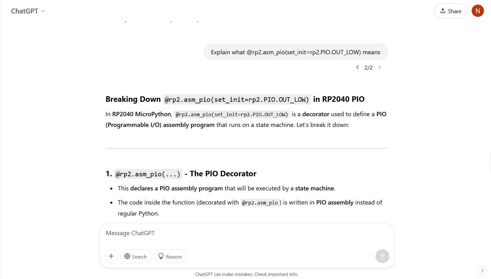
Prompt 3: Explain what @rp2.asm_pio(set_init=rp2.PIO.OUT_LOW) means
The decorator @rp2.asm_pio(set_init=rp2.PIO.OUT_LOW) is used in MicroPython to define a PIO (Programmable Input/Output) program for the RP2040 microcontroller.
🧩 Breakdown:
@rp2.asm_pio: This decorator indicates that the following function is a PIO assembly program.set_init=rp2.PIO.OUT_LOW: This parameter sets the initial state of the 'set' pins to a low logic level (0) when the state machine is initialized.
✅ Purpose:
This setup ensures that the specified GPIO pins controlled by the PIO program start in a known low state, which can be important for predictable behavior in hardware applications.
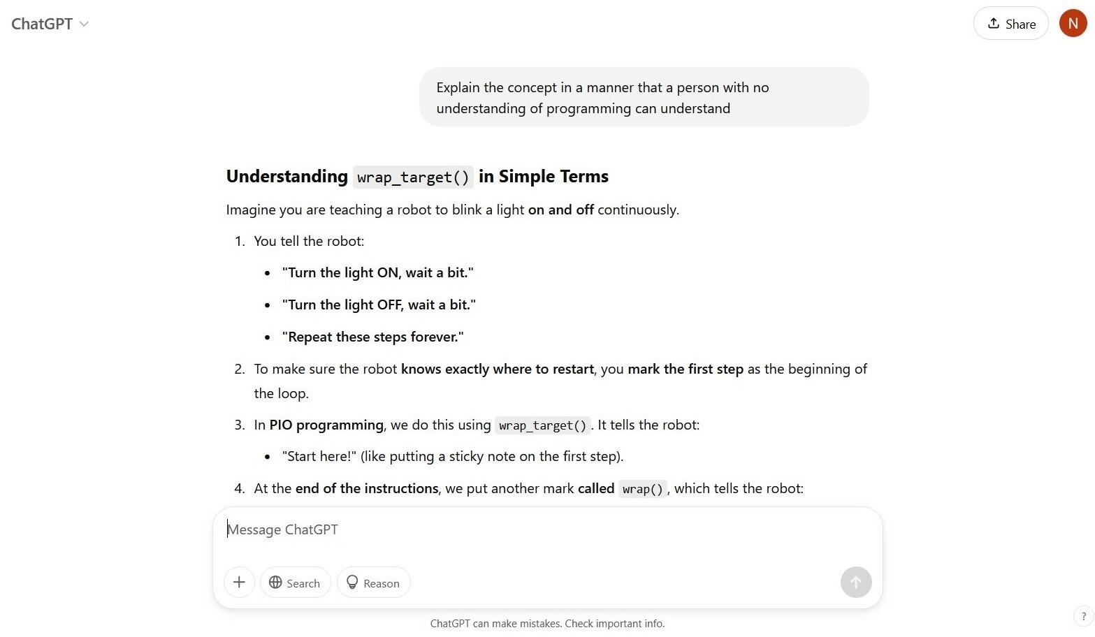
Prompt 4: Explain wrap_target
In PIO assembly for the RP2040, wrap_target and wrap are used to define a loop in your program.
🧩 Breakdown:
wrap_target: Marks the beginning of the loop.wrap: Marks the end of the loop. When the program counter reaches this point, it wraps back towrap_target.
✅ Purpose:
This mechanism allows the PIO program to execute a set of instructions repeatedly, which is essential for tasks like continuous data transmission or signal generation.
Prompt 5: Explain the concept in a manner that a person with no understanding of programming can understand
Imagine you have a helper who can perform a specific task repeatedly without you having to tell them each time. You give them a simple set of instructions, and they follow them over and over again.
In the RP2040 microcontroller, this helper is called a state machine. It's like a mini-worker inside the chip that can control things like lights or motors by following the instructions you provided.
This allows the main part of the microcontroller to focus on other tasks, while the state machine handles its job independently and efficiently.
Prompt 6: What do you mean by 32 instructions in state machines
In the RP2040's PIO (Programmable Input/Output) system, each PIO block has a shared instruction memory that can hold up to 32 instructions. These instructions are written in a simple assembly language specific to PIO.
Each of the four state machines within a PIO block can execute these instructions. However, the total number of unique instructions across all state machines in a PIO block cannot exceed 32.
This limitation encourages efficient programming and reuse of instructions among state machines when possible.
Prompt 7: Are 32 instructions 32 bits?
Each instruction in the RP2040's PIO system is 16 bits wide. The instruction memory can hold up to 32 such instructions.
Therefore, the total size of the instruction memory per PIO block is 32 instructions × 16 bits = 512 bits or 64 bytes.
This compact size is sufficient for many simple I/O tasks that PIO is designed to handle.
Prompt 8: What is a bit
A bit is the most basic unit of information in computing and digital communications. It can have a value of either 0 or 1.
Bits are the building blocks of all digital data, representing binary states such as on/off, true/false, or yes/no.
Prompt 9: What is a byte
A byte consists of 8 bits. It is a standard unit of data in computer systems and is used to represent a wide range of information, such as a single character in text.
For example, the letter 'A' is represented by the byte 01000001 in binary.
Prompt: What are these states in state machines in RP2040?
In the context of the RP2040 microcontroller, a state machine within the Programmable I/O (PIO) subsystem refers to a specialized hardware component designed to execute a sequence of instructions that control input/output operations with precise timing. These state machines are not "states" in the traditional sense of state diagrams but are autonomous processors that manage I/O tasks independently of the main CPU.
Each RP2040 contains two PIO blocks, and each block comprises four state machines, totaling eight per device. These state machines can be programmed with up to 32 instructions stored in a shared instruction memory. They operate independently, allowing for concurrent handling of multiple I/O protocols or tasks.
Key features of RP2040's PIO state machines include:
- Independent Execution: Each state machine can run its own program, enabling parallel processing of I/O operations.
- Shared Instruction Memory: The four state machines within a PIO block share a 32-instruction memory, allowing for efficient code reuse and compact program design.
- FIFO Buffers: Each state machine has transmit (TX) and receive (RX) FIFO buffers to facilitate data exchange with the main processor.
- Shift Registers: Input Shift Register (ISR) and Output Shift Register (OSR) are used for serial data handling, enabling bit-level manipulation.
- Scratch Registers: X and Y registers serve as general-purpose storage for temporary data or loop counters.
- GPIO Control: State machines can directly control General Purpose Input/Output (GPIO) pins, allowing for custom protocol implementation.
- Deterministic Timing: Operating independently from the main CPU ensures consistent timing, crucial for protocols requiring precise signal control.
By leveraging these state machines, developers can offload time-critical I/O tasks from the main processor, enabling efficient and reliable communication with various peripherals.
Prompt 1: What are instructions in the context of PIO?
In the RP2040's Programmable I/O (PIO) system, instructions are simple commands that control the behavior of state machines. Each instruction is 16 bits wide, and a PIO program can contain up to 32 such instructions. These instructions enable the state machines to perform tasks like reading from or writing to GPIO pins, moving data between registers, and controlling program flow.
The PIO instruction set includes commands such as IN, OUT, PUSH, PULL, MOV, IRQ, WAIT, JMP, and SET. Despite the limited number of instructions, they are powerful enough to implement complex I/O protocols and timing-sensitive operations.
Prompt 2: What is FIFO?
FIFO stands for "First-In, First-Out." In the context of the RP2040's PIO system, each state machine has two FIFOs: a transmit (TX) FIFO and a receive (RX) FIFO. These FIFOs are used to buffer data between the main processor and the PIO state machines.
Data written to the TX FIFO by the main processor can be read by the state machine using the pull instruction. Conversely, the state machine can write data to the RX FIFO using the push instruction, and the main processor can read this data. This mechanism allows for efficient and asynchronous data exchange between the CPU and the PIO.
Prompt 3: What is IO Mapping?
IO Mapping in the RP2040 refers to the association between PIO state machine instructions and specific GPIO pins. When configuring a state machine, you can specify base pins for various operations:
set_base: Base pin forsetinstructions.out_base: Base pin foroutinstructions.in_base: Base pin forininstructions.sideset_base: Base pin for side-set operations.
By setting these base pins, you define which GPIOs the state machine will control or monitor. This mapping is crucial for ensuring that the PIO program interacts with the correct physical pins on the microcontroller.
Prompt 4: What is the instruction memory and what are its key features?
The RP2040's PIO system includes an instruction memory that stores the programs executed by the state machines. Each PIO block has a shared instruction memory capable of holding up to 32 instructions, with each instruction being 16 bits wide.
Key features of the instruction memory include:
- Shared among all four state machines within a PIO block.
- Allows for efficient use of memory by sharing common instructions.
- Supports a limited yet powerful set of instructions tailored for I/O operations.
- Facilitates precise timing and control over GPIO interactions.
This design enables the RP2040 to handle complex I/O tasks with minimal CPU intervention.
Prompt 5: Explain the different registers in a state machine
Each PIO state machine in the RP2040 has several registers that facilitate its operation:
- Input Shift Register (ISR): Temporarily holds data shifted in from GPIO pins using the
ininstruction. - Output Shift Register (OSR): Holds data to be shifted out to GPIO pins using the
outinstruction. - X and Y Scratch Registers: General-purpose registers used for temporary storage and loop counters.
- Program Counter (PC): Keeps track of the current instruction being executed.
These registers work together to enable the state machine to perform complex I/O operations with precise timing and minimal CPU involvement.
Prompt 6: Why is a separate X or Y register required?
The X and Y registers in the RP2040's PIO state machines serve as general-purpose scratch registers. They are essential for implementing loops, counters, and conditional operations within PIO programs.
For example, you can use the jmp x-- instruction to create a loop that executes a specific number of times. By initializing the X register with a value and decrementing it with each iteration, the loop continues until X reaches zero. This mechanism allows for precise control over the number of repetitions in timing-critical applications.
Prompt 7: Explain this set(pins,10) [31]
The instruction set(pins, 10) [31] in a PIO program performs the following actions:
set(pins, 10): Sets the output pins to the binary value1010. This means that the corresponding GPIO pins will be set high or low according to this pattern.[31]: Introduces a delay of 31 cycles after executing the instruction. This delay ensures that the output state is maintained for a specific duration.
This instruction is useful for generating precise timing signals, such as square waves or custom communication protocols, by controlling the duration of high and low states on the output pins.
Prompt 8: How does 10 turn LED low?
In the context of the instruction set(pins, 10), the value 10 is a binary representation (1010) that sets specific GPIO pins high or low. Each bit corresponds to a pin, with 1 indicating high and 0 indicating low.
If the LED is connected to a pin corresponding to a 0 in this pattern, that pin will be set low, turning the LED off. Conversely, a 1 would set the pin high, potentially turning the LED on, depending on the circuit configuration.
Therefore, the value 10 sets certain pins low, which can result in turning off LEDs connected to those pins.
Prompt 1: Explain sm = rp2.StateMachine(0, blink, freq=2000, set_base=machine.Pin(25))
This line of code initializes a Programmable I/O (PIO) state machine on the Raspberry Pi Pico using MicroPython:
sm = rp2.StateMachine(0, blink, freq=2000, set_base=machine.Pin(25)):0: Specifies that state machine 0 is being used.blink: The PIO program to be executed by the state machine.freq=2000: Sets the execution frequency of the state machine to 2000 Hz.set_base=machine.Pin(25): Assigns GPIO pin 25 as the base pin for thesetinstructions in the PIO program.
This configuration allows the state machine to control GPIO pin 25 based on the instructions defined in the blink PIO program.
Prompt 2: Is StateMachine 0 being used here?
Yes, in the line sm = rp2.StateMachine(0, blink, freq=2000, set_base=machine.Pin(25)), state machine 0 is being utilized. The first argument 0 passed to rp2.StateMachine specifies that state machine number 0 is to be used. The RP2040 microcontroller has multiple state machines, and this line selects the first one for the blink program.
Prompt 3: Explain sm.active(1)
The line sm.active(1) activates the state machine that was previously configured. Here's what it does:
sm: Refers to the state machine instance created earlier..active(1): Starts the execution of the PIO program associated with the state machine. Passing1as an argument sets the state machine to active mode.
Once activated, the state machine begins executing its PIO program independently of the main CPU, allowing for precise and efficient control of GPIO operations.
This is the github documentation that describes how each insruction is programmed.
In Wokwi simulation
This is the code for the same
                                #importing required modules and objects
                                import rp2
                                from machine import Pin
                                import utime

                                #setting up PIO with a decorator @rp2.asm_pio(...) to initialize the Pin state to LOW
                                @rp2.asm_pio(set_init=(rp2.PIO.OUT_LOW))

                                #creating a function 'blink'
                                def blink ():
                                    wrap_target() #creates a start point for when the program loops
                                    set(pins,1) [31] #turn predefined pin to HIGH, ie. LED turns ON
                                    nop() [31] #no-operation instruction; do nothing for 31 cycles
                                    nop() [31]
                                    nop() [31]
                                    nop() [31]
                                    #160 cycles

                                    set (pins,0) [31] #turn predefined pin to LOW, ie. LED turns OFF
                                    nop() [31]
                                    nop() [31]
                                    nop() [31]
                                    nop() [31]
                                    wrap() #go back to start point (wrap_target) and start again

                                #configure state machine 0 to run PIO program named blink at a frequency of 2000 times per second
                                sm = rp2.StateMachine(0,blink,freq=2000,set_base=machine.Pin(25))

                                while True:
                                    print("State machine starting...") #print statement in console
                                    sm.active(1) # start state machine
                                    utime.sleep(1) #delay of 1 second
                                    print("State machine stopping...")  #print statement in console
                                    sm.active(0) # stop state machine
                                    utime.sleep(1)
Program 3: Find the I2C address of the OLED Display
In Output Devices Week I was able to play with Wokwi a bit more, so I have added my work here as well.
The first step to programming on the OLED is using to find the I2C Address of our device, the SSD1306 OLED in our case. For this I am going to adapt the code from this tutorial to do so. To understand more about each line of code, I use the help of ChatGPT
Prompt 1: Explain each line of code as if I am a beginner to programming.
Original Code:
    #include <Wire.h>

    void setup()
    {
    Serial.begin (115200);
    while (!Serial)
    {
    }

    Serial.println ();
    Serial.println ("I2C scanner. Scanning ...");
    byte count = 0;
    pinMode(13,OUTPUT);
    digitalWrite(13,HIGH);
    Wire.begin();
    for (byte i = 1; i < 120; i++)
    {
        Wire.beginTransmission (i);
        if (Wire.endTransmission () == 0)
        {
        Serial.print ("Found address: ");
        Serial.print (i, DEC);
        Serial.print (" (0x");
        Serial.print (i, HEX);
        Serial.println (")");
        count++;
        delay (1);
        }
    }
    Serial.println ("Done.");
    Serial.print ("Found ");
    Serial.print (count, DEC);
    Serial.println (" device(s).");
    }

    void loop() {}
This is an I2C scanner program written for an Arduino. It scans for devices connected to the I2C (Inter-Integrated Circuit) bus and prints their addresses to the serial monitor.
1. Including the Required Library
#include <Wire.h>
Includes the Wire library to enable I2C communication.
2. Setup Function
void setup()
The setup() function runs once at the start.
3. Initializing Serial Communication
Serial.begin(115200);
Starts serial communication at 115200 baud rate.
while (!Serial) {}
Waits for the Serial Monitor to open (useful for some boards).
4. Starting the Scan
Serial.println("I2C scanner. Scanning ...");
Prints a message indicating that the I2C scan is starting.
byte count = 0;
Initializes a variable to count detected I2C devices.
5. Configuring an LED Indicator
pinMode(13, OUTPUT);
                    digitalWrite(13, HIGH);
Turns on the built-in LED on pin 13.
6. Initializing I2C Communication
Wire.begin();
Starts the I2C communication.
7. Scanning for I2C Devices
for (byte i = 1; i < 120; i++)
Loops through all possible I2C addresses (1 to 119).
Wire.beginTransmission(i);
Attempts to start communication with the device at address i.
if (Wire.endTransmission() == 0)
Checks if the device acknowledges communication.
Serial.print("Found address: ");
Prints the detected I2C device address.
delay(1);
Adds a 1-millisecond delay to avoid overloading the I2C bus.
8. Completing the Scan
Serial.println("Done.");
Indicates that the scan is complete.
9. Loop Function
void loop() {}
The loop() function is empty since the scan is done only once.
10. Usage
- Upload the code to an Arduino board.
- Open the Serial Monitor (set baud rate to 115200).
- See detected I2C addresses of connected devices.
11. Why is this useful?
It helps find the I2C addresses of unknown devices, which is useful for working with sensors, displays, or motor controllers.
Prompt: Why should the variable be byte?
The variable byte is used in this Arduino I2C scanner program for efficiency and to match the expected data type for I2C addresses. Here’s why:
1. Memory Efficiency
- A
bytein Arduino is an 8-bit unsigned integer (0-255). - I2C addresses range from 0 to 127, which fits within a
byte. - Using a
byteinstead of anint(which is 16-bit) saves memory.
2. Matching I2C Address Format
- The function
Wire.beginTransmission(i)expects an 8-bit address. - Since
byteis 8-bit, it avoids unnecessary type conversions.
3. Faster Execution
- On 8-bit microcontrollers (e.g., ATmega328P in Arduino Uno),
byteoperations are faster. - Using an
int(16-bit) would require extra processing, slightly slowing execution.
Alternative:
If working with 10-bit I2C addressing, uint16_t (16-bit unsigned integer) would be a better choice.
Conclusion: Using byte in this case is memory-efficient, type-appropriate, and optimized for performance. 🚀
Prompt: What is an unsigned integer?
An unsigned integer is a type of integer that only stores non-negative values (0 and positive numbers). Unlike signed integers, which can be positive or negative, unsigned integers do not have a sign.
1. No Negative Numbers
- Signed integers store both negative and positive numbers (e.g., -10, 0, 25).
- Unsigned integers only store positive numbers and zero (e.g., 0, 1, 255).
2. Increased Positive Range
- Since no bits are used for the sign, unsigned integers can store larger positive values in the same memory space.
- Example (for an 8-bit integer):
- Signed 8-bit integer: -128 to 127
- Unsigned 8-bit integer: 0 to 255
3. Common Use Cases
- When negative numbers aren’t needed, using unsigned integers saves memory and extends the range.
- Examples:
- I2C addresses (0-127)
- Sensor readings (e.g., distance in millimeters)
- Loop counters (if always positive)
4. Example in Arduino
                    byte value = 200;  // 'byte' is an 8-bit unsigned integer (0-255)
                    unsigned int largeValue = 50000;  // 16-bit unsigned integer (0-65535)
If you try to store -5 in an unsigned integer, it will wrap around to a large positive number due to underflow.
Let me know if you need more details! 🚀
Now that I have some understanding of what the code means, I will rewrite it for my purposes using ESP32S3 microcontroller in Wokwi simulator.
- Since the RGB LED is driven by GPIO 38, I will use set that pin as an output in
void setup() - Since the default pins for ESP32-S3 I2C communication are
GPIO 8 (SDA)&GPIO 9 (SCL), I will be connecting my OLED screen here
I was hoping to be able to write this code without looking to promote learning the logic behind it, but I had to refer back to the source with every line.
Now to sort some errors I made while coding. Debugging seems to be the most important part of coding, because while trying to fox your code, you tend to learn the best about what each line of code does and the pros and cons of different code logic. Even if you dont truly understand it while writing it, you tend to understand much more while debugging.
This is a video of the working. As you can see the I2C address of the SSD1306 module is 0x3C, which can be confirmed by Wokwi's reference documentation
    #include <Wire.h>

    #define RGB 38
    #define SDA 8
    #define SCL 9

    void setup(){
        Serial.begin(115200);
        // while(!Serial){}
        Serial.println("I2C Scanner scanning...");
        byte count=0;
        pinMode(RGB,OUTPUT);
        digitalWrite(RGB,HIGH);
        Wire.begin();

        for (byte i=1; i<120; i++){
        Wire.beginTransmission(i);
        // Serial.println (Wire.endTransmission());
        if (Wire.endTransmission()==0){
            // Serial.println (Wire.endTransmission());
            Serial.print ("Found Address: ");
            Serial.print(i, DEC);
            Serial.print(" (0x");
            Serial.print(i, HEX);
            Serial.println(")");
            count++;
            delay(1);
        }
        }
        Serial.print("Done. ");
        Serial.print("Found ");
        Serial.print(count, DEC);
        Serial.print(" device(s)");
    }

    void loop(){}
Program 4: Add text to your display
I will be following the code examples seen here for reference and to get familiar with programming the OLED display.
To understand the some parts of the code I used the help of ChatGPT and confirmed with one of the examples from Adafruit_SDD1306 library
Adafruit_SSD1306 display(Height, Width, &Wire, -1);
Prompt 1 : Explain this code to me:
Adafruit_SSD1306 display(Height, Width, &Wire, -1);
This line of code initializes an Adafruit SSD1306 OLED display object using the Adafruit_SSD1306 library.
Adafruit_SSD1306 display(Height, Width, &Wire, -1);Explanation of Parameters:
- Height → The height (in pixels) of the OLED display (e.g.,
32or64). - Width → The width (in pixels) of the OLED display (e.g.,
128). - &Wire → A reference to the I2C communication interface.
Wireis the default I2C object for communication. - -1 → The reset pin number.
- If
-1, the display does not have a dedicated reset pin, and a software reset is used. - Otherwise, you should specify the GPIO pin number connected to the display’s reset pin.
- If
Example Initialization:
For a 128x64 OLED display using I2C:
Adafruit_SSD1306 display(128, 64, &Wire, -1);For a 128x32 OLED display using I2C:
Adafruit_SSD1306 display(128, 32, &Wire, -1);Prompt 2 : Explain this code to me
if(!display.begin(SSD1306_SWITCHCAPVCC, 0x3C)) { // Address 0x3D for 128x64
                            Serial.println(F("SSD1306 allocation failed"));
                            for(;;);
                        }
Understanding the Code
This block of code initializes an SSD1306 OLED display and checks whether the initialization was successful.
Breaking It Down
1️⃣ display.begin(SSD1306_SWITCHCAPVCC, 0x3C)
- Initializes the OLED display.
- Parameters:
SSD1306_SWITCHCAPVCC→ Uses an internal charge pump for power.0x3C→ I2C address of the display (some models use0x3D).
2️⃣ if (!display.begin(...))
- The
!(logical NOT) operator negates the result ofdisplay.begin(). - If the initialization fails,
display.begin()returnsfalse, making!false → true. - This triggers the error-handling block.
3️⃣ Serial.println(F("SSD1306 allocation failed"));
- Prints an error message to the Serial Monitor if initialization fails.
F("...")stores the string in Flash memory (PROGMEM) to save RAM.
4️⃣ for(;;); → Infinite Loop (Halt Execution)
for(;;);is an infinite loop that prevents further code execution.- If the display fails, the program stays in this loop to prevent further errors.
What Happens in Different Scenarios?
| OLED Initialization | display.begin() Returns |
if(!display.begin(...)) Evaluates To |
Outcome |
|---|---|---|---|
| Successful | true |
false |
Code continues normally |
| Failed | false |
true |
Error message printed, program halts |
        #include <Wire.h>
        #include <Adafruit_GFX.h>
        #include <Adafruit_SSD1306.h>

        #define Height 128
        #define Width 64

        Adafruit_SSD1306 display(Height,Width,&Wire,-1);

        void setup(){
            Serial.begin(115200);

            if (!display.begin(SSD1306_SWITCHCAPVCC, 0x3C)){
            Serial.println ("I2C initialisation failed");
            for(;;);
            }
            delay(200);

            display.clearDisplay();
            display.setTextSize(1);
            display.setTextColor(WHITE);
            display.setCursor(0,0);
            display.println("Hello world!");
            display.display();
        }

        void loop(){
        }
Program 5: Display a Facial Expression in the OLED Display
To make life a bit easier, I was going to try to use the FluxGarage RoboEyes library, which is based on the Adafruit GFX Library, so it should work with ESP32 as well. However, it won't be possible to simulate on Wokwi, since only paying customers can add custom libraries that are not yet made available for free in the library manager.
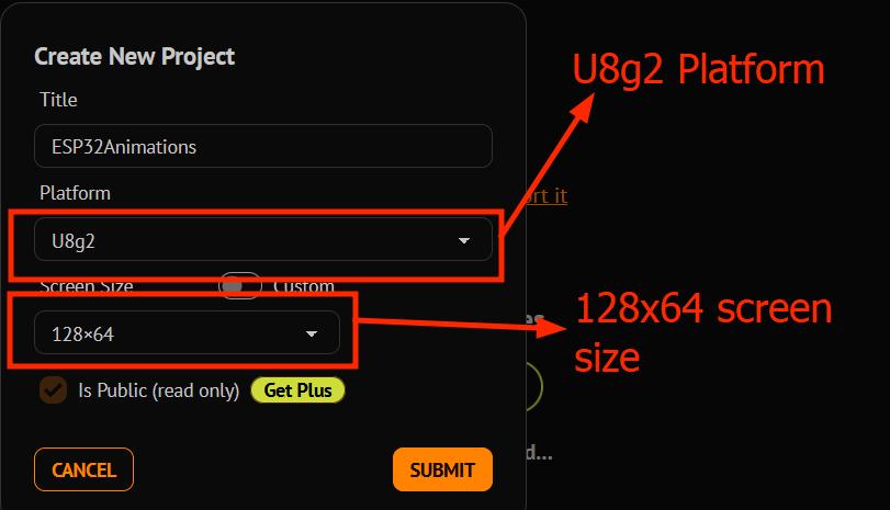
So instead I am going to use this tutorial that uses the U8g2 library, which is supported by Wokwi simulator
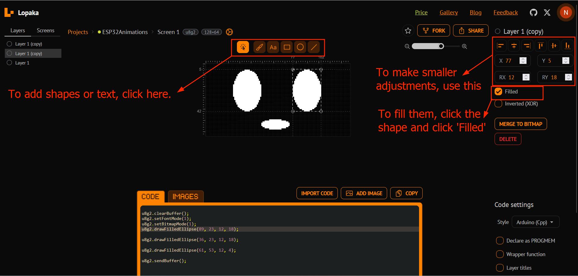
Following the tutorial I went to Lopaka.app, selected the U8g2 library, and created a new project
This is a youtube video that shows the basic overview of using the Lopaka app
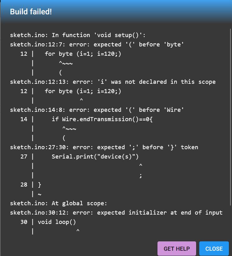
Whenever I face errors, I use ChatGPT to understand what the error message actually means and what I have to do to solve it
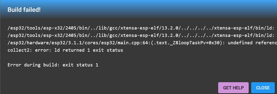
Prompt 1: Please explain this error in Wokwi
                                    /esp32/tools/esp-x32/2405/bin/../lib/gcc/xtensa-esp-elf/13.2.0/../../../../xtensa-esp-elf/bin/ld:
                                    /core/core.a(main.cpp.o):(.literal._Z8loopTaskPv+0xc): undefined reference to `_Z4loopv'

                                    /esp32/tools/esp-x32/2405/bin/../lib/gcc/xtensa-esp-elf/13.2.0/../../../../xtensa-esp-elf/bin/ld:
                                    /core/core.a(main.cpp.o): in function `_Z8loopTaskPv':

                                    /esp32/hardware/esp32/3.1.1/cores/esp32/main.cpp:64:(.text._Z8loopTaskPv+0x30): undefined reference to `_Z4loopv'

                                    collect2: error: ld returned 1 exit status

                                    Error during build: exit status 1
This error in Wokwi is a linker error, meaning the compiler successfully compiled your code, but the linker failed to resolve a reference to the function _Z4loopv. Let's break it down:
Understanding the Error
- The error mentions an "undefined reference to `_Z4loopv`".
_Z4loopvis the mangled name of the functionloop()in C++.- This means the linker couldn't find an implementation of the
loop()function.
The error originates from main.cpp in the ESP32 core, specifically from loopTaskPv, which is the FreeRTOS task responsible for running the loop() function.
Possible Causes & Fixes
1. Missing loop() Function
The Arduino framework requires both setup() and loop() functions. If loop() is missing, the linker will fail.
Fix: Add the missing loop() function in your sketch.
                        void setup() {
                            Serial.begin(115200);
                            Serial.println("Setup complete.");
                        }

                        void loop() {
                            Serial.println("Loop running...");
                            delay(1000);
                        }
2. Incorrect Function Signature
Even if you define loop(), the function signature must be:
                        void loop() {
                            // Your code here
                        }
If you accidentally define it incorrectly (e.g., int loop() or void loop(int)), the linker won't recognize it.
Fix: Ensure loop() has the correct signature.
3. Corrupt or Incomplete Wokwi Project
Sometimes, Wokwi might not properly load all required files.
Fix: Try the following:
- Refresh Wokwi (
Ctrl+Shift+R). - Create a new ESP32 project in Wokwi and copy your code.
- Ensure you are using the correct ESP32 board in Wokwi.
4. Custom main() Instead of Arduino Framework
If you're writing custom ESP32 code (not using the Arduino framework), you must provide your own loop() or redefine the main execution.
Fix: Either:
- Stick to the standard
setup()andloop(). - If you're using
main(), you need to handle the main execution loop yourself.
Conclusion
This error happens because the ESP32 Arduino core expects a loop() function, and it’s missing. The simplest fix is to define a valid loop() function in your code. If the problem persists, try resetting Wokwi or using a fresh ESP32 project.
Let me know if you need more help! 🚀
Prompt 2: Explain this error message to me: "sketch.ino:4:16: error: expected identifier before numeric constant"
This error occurs because SCLpin is being used incorrectly in the code.
Issue:
- The macro definition
#define SCLpin 6is conflicting with existing identifiers. - In C++, predefined macros or function names cannot be redefined as constants.
Fix:
Use uppercase naming conventions to avoid conflicts:
#define SCL_PIN 6
#define SDA_PIN 5Prompt 3: Explain this error message: "undefined reference to `_Z4loopv'"
This error occurs when the compiler cannot find the definition of the loop() function.
Possible Causes:
- The
loop()function is missing. - The function name is misspelled.
- There is a missing function prototype or implementation.
Fix:
Ensure that loop() is defined in the sketch:
void loop() {
                            // Your code here
}Prompt 4: Code is compiling but Display is not showing anything
If the display is not showing anything, the issue could be due to incorrect wiring, incorrect I2C address, or missing initialization.
Debugging Steps:
- Check the I2C pins: ESP32 default I2C pins are SDA: GPIO 21, SCL: GPIO 22.
- Run an I2C scanner to find the display address:
#include <Wire.h>

                        void setup() {
                            Serial.begin(115200);
                            Wire.begin(21, 22);
                            Serial.println("Scanning I2C devices...");
                            for (byte address = 1; address < 127; address++) {
                                Wire.beginTransmission(address);
                                if (Wire.endTransmission() == 0) {
                                    Serial.print("I2C device found at 0x");
                                    Serial.println(address, HEX);
                                }
                                delay(10);
                            }
                        }

                        void loop() {}
Fix:
- Verify power connections: VCC → 3.3V or 5V, GND → GND.
- Use correct I2C address in the initialization.
                            #include <U8g2lib.h>
                            #include <Wire.h>

                            // #define SCL_PIN 6
                            // #define SDA_PIN 5
                            // U8G2_SSD1306_128X64_NONAME_F_HW_I2C(rotation, [reset [, clock, data]]) [full framebuffer, size = 1024 bytes]

                            U8G2_SSD1306_128X64_NONAME_F_HW_I2C u8g2(U8G2_R0, /*SCL_PIN, SDA_PIN,*/ U8X8_PIN_NONE);

                            void setup(){
                                Serial.begin(9600);
                                if (!u8g2.begin()){
                                Serial.println("Display not initialized");
                                for(;;);
                                }
                                delay(1000);
                                Serial.println("Display initialized");
                            }

                            void eye_open(){
                                u8g2.clearBuffer();
                                u8g2.setFontMode(1);
                                u8g2.setBitmapMode(1);
                                u8g2.drawFilledEllipse(36, 23, 12, 18);
                                u8g2.drawFilledEllipse(89, 23, 12, 18);
                                u8g2.drawFilledEllipse(61, 53, 12, 4);
                                u8g2.sendBuffer();
                            }

                            void loop(){
                                eye_open();
                            }
Program 6: Testing on a development board
I tested some of my previous code in a development board called Seeed Xiao RP2040
Try different languages &/or development environments
I used ATtiny 1614 and Arduino IDE and UPDI tool chain to make an LED blink.
This is the code I used for the same:
                            #define LED 10 #defining pin in a variable

                            void setup(){
                            pinMode(LED,OUTPUT); #setting up LED as an output pin
                            }

                            void loop(){
                            digitalWrite(LED,HIGH); #LED turns ON
                            delay(1000); #delay of 1 second
                            digitalWrite(LED,LOW); #LED turns OFF
                            delay(1000);
                            }
More information can be found in the group assignment.
Program 7: Using the STM32 microcontroller
This time I wanted to do something more relevant to my final project. Since I was already familiar programming in C++ with the Arduino IDE and based on a suggestion by my instructor Sibin, I chose to simulate a program in the NUCLEO-C031C6
When I was facing some difficulty finding all required information, my instructor told me to use STM32CUbeMX software, which is a graphical tool normally used to configure STM32 microntrollers and microprocessors.
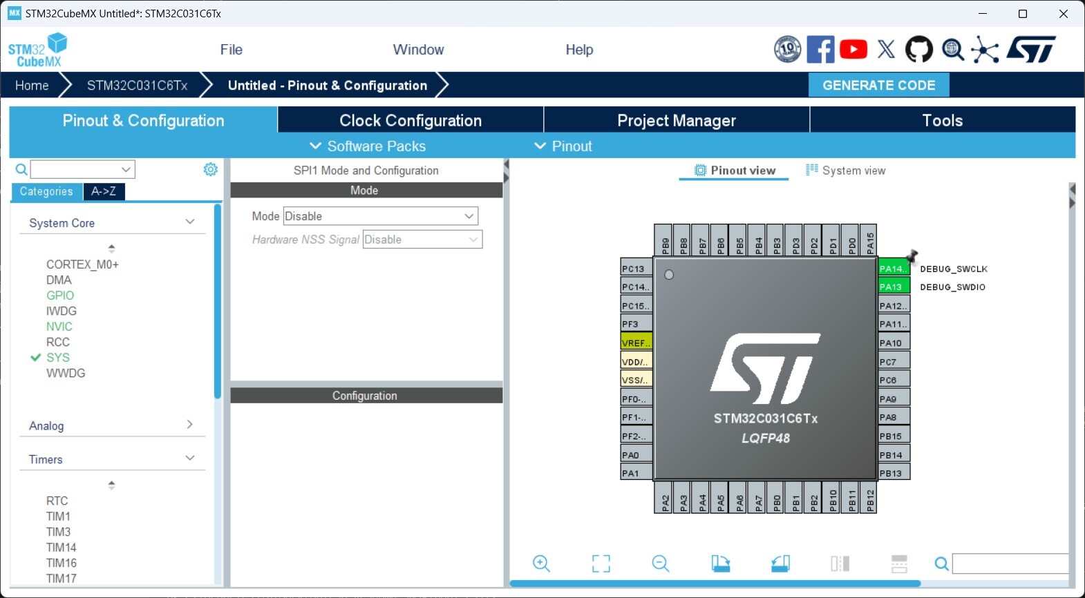
I used it here to find other information that I was not able to get easily from the datasheet, for eg: the pins for SWD debugging.
Conclusion
This week I learnt the following:
- learnt about computer architectures and their differences
- learnt about different toolchains for different microchips and programming languages
- learnt to program in Micropython and Arduino C++ in an RP2040 microchip & an ATTiny1614
Mistakes, Solutions & Tips
Tips: To find out which PORT is being connected to your board, you can use the Device Manager > COM and Ports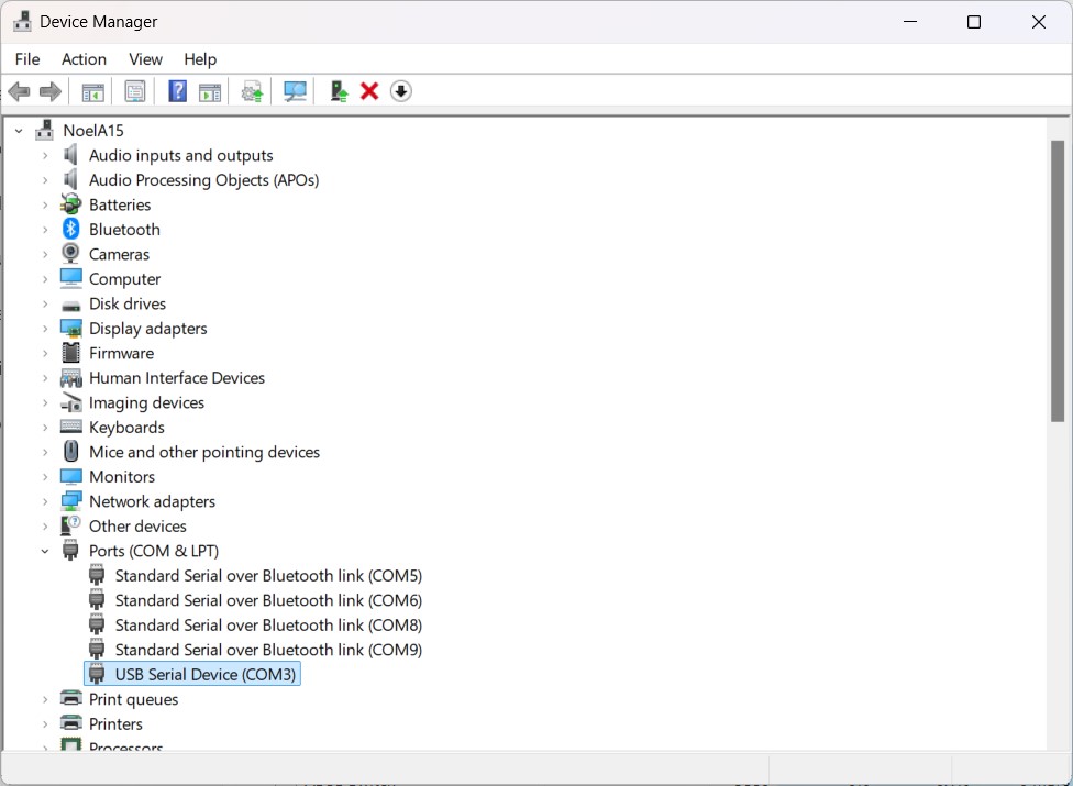
References
- Week 4 Group Assignment: Comparing Toolchains and Development Workflows of Different Computer Architectures.
- Offical datasheet for RP2040 by Rasberry Pi
- Abouts CPU Cores
- About the ARM Cortex-M0+ processor
- Wikipedia article on the ARM architecture family
- Wikipedia article explaining the
floorfunction - Wikipedia article explaining flash memory.
- "Raspberry Pi Pico Getting Started Tutorial with MicroPython" Tutorial by Yusro explaining the significance of each of the digits in the name of the chip RP2040
- Phased-locked loop by Wikipedia
- What is Analog to Digital Converter & Its Working by elprocus.com
- An article on Static Random Access Memory by Unacademy
- The Ultimate Guide to QFN Package by anysilicon.com
- Hardware design with RP2040
- What is the logic level voltage of the Arduino microcontroller? by a Reddit user
- 'Getting Started with Seeed Studio XIAO RP2040' by Seeed Studio
- 'What is PIO?' by Rasberry Pi
- RP2040 Datasheet
- Raspberry Pi Pico-series Python SDK
- Github documentation for the rp2 module, used to program the PIO in RP2040