12. Group Assignment
This week's brief:
Group assignment:
GROUP ASSIGNMENT
You can view our group assignment here!
INDIVIDUAL ASSIGNMENT
Brainstorming and Project planning
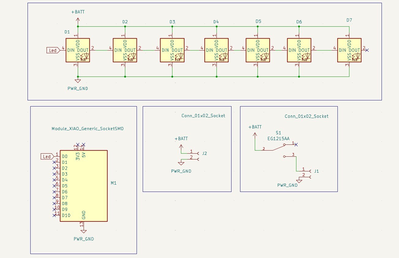
System Design
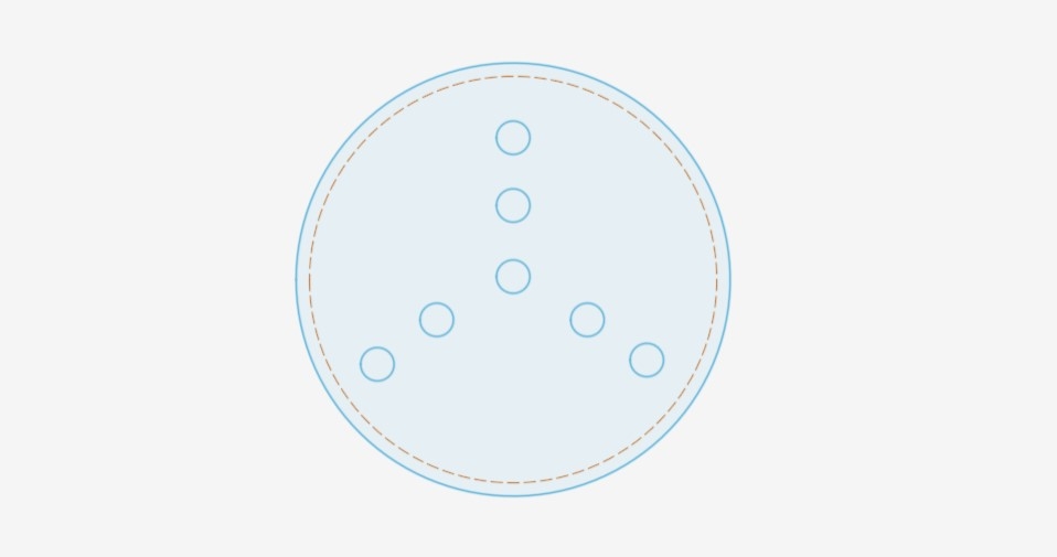
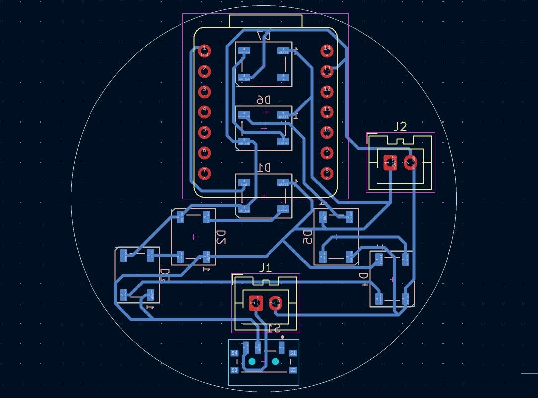
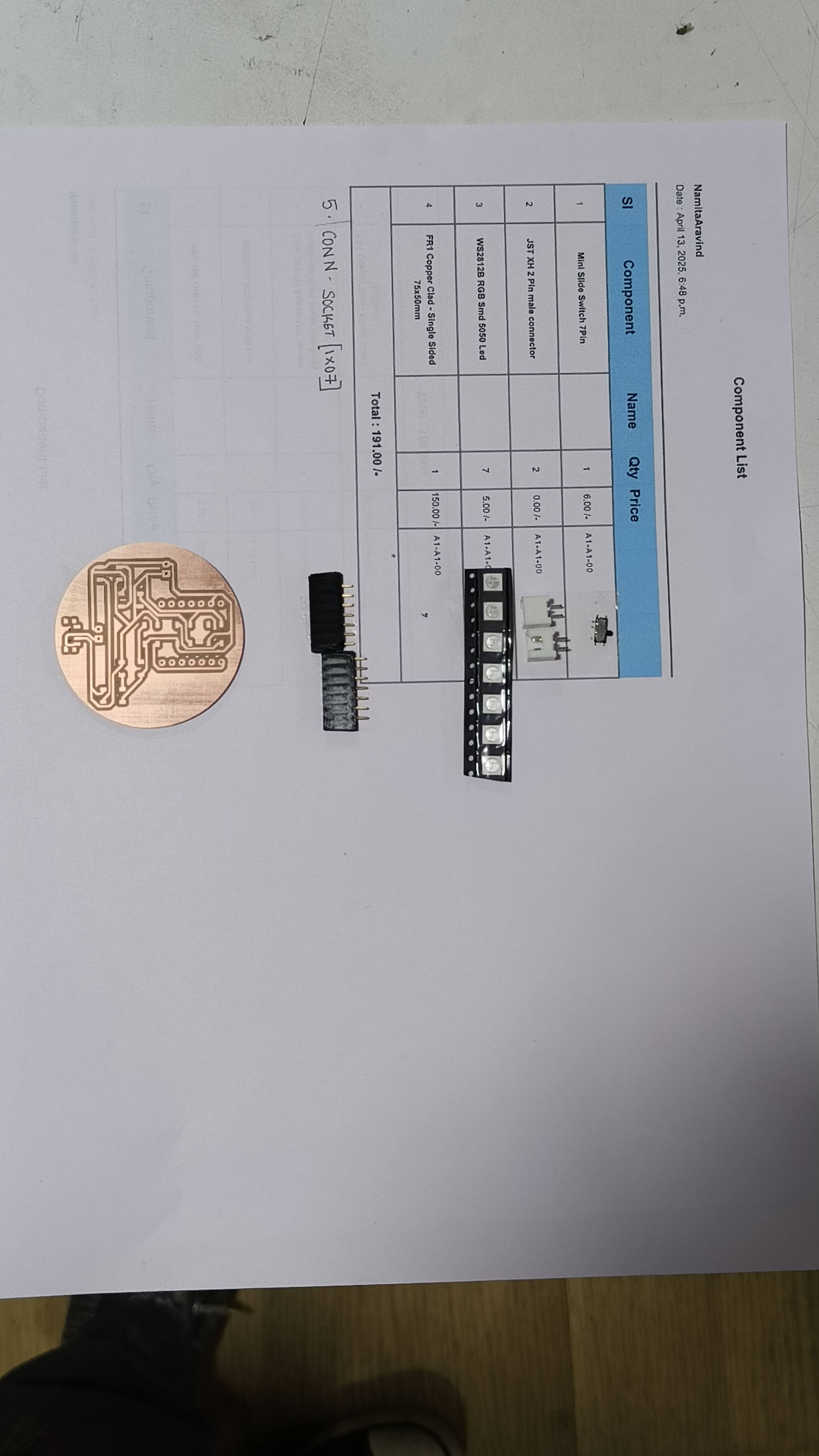
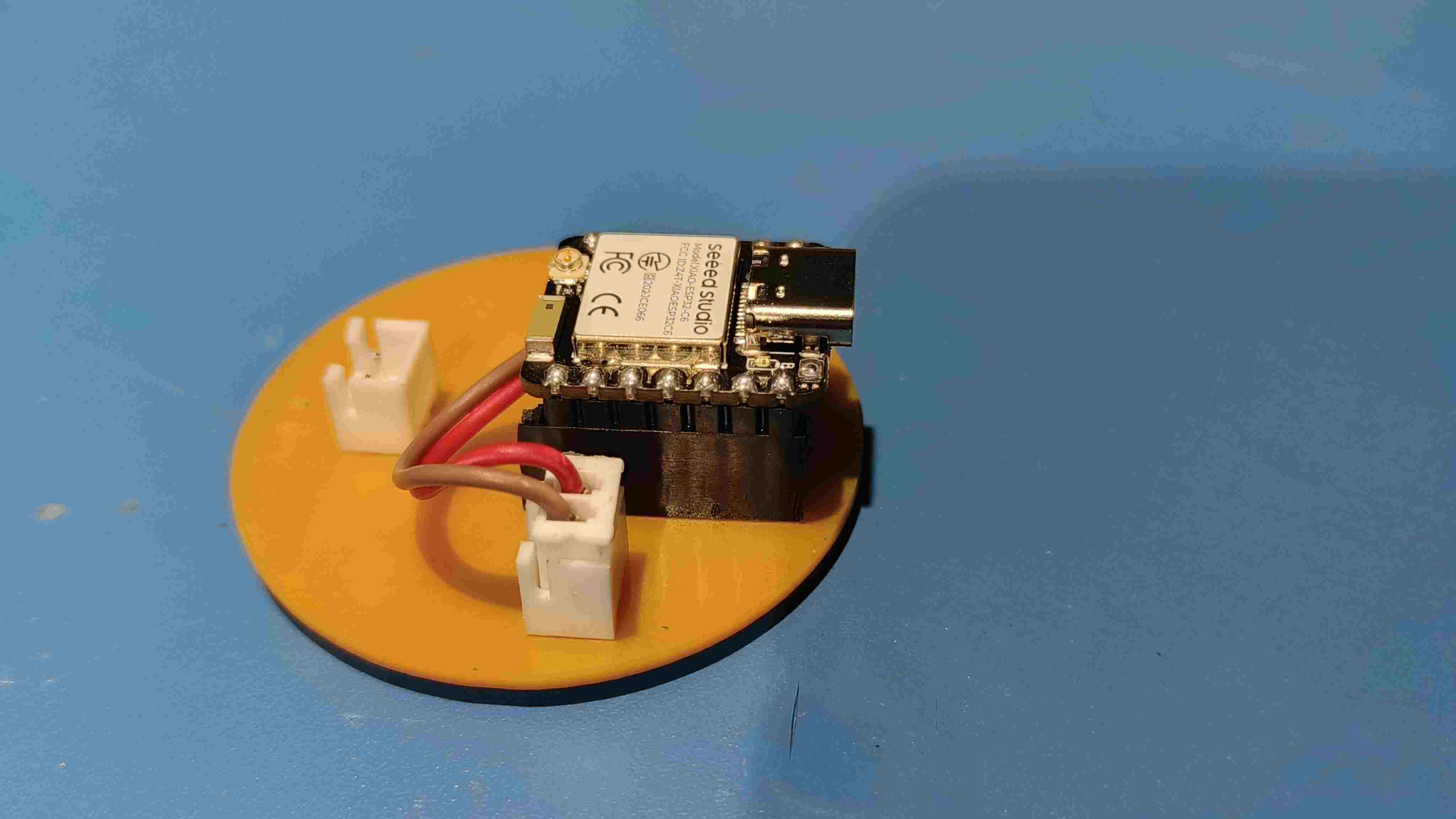
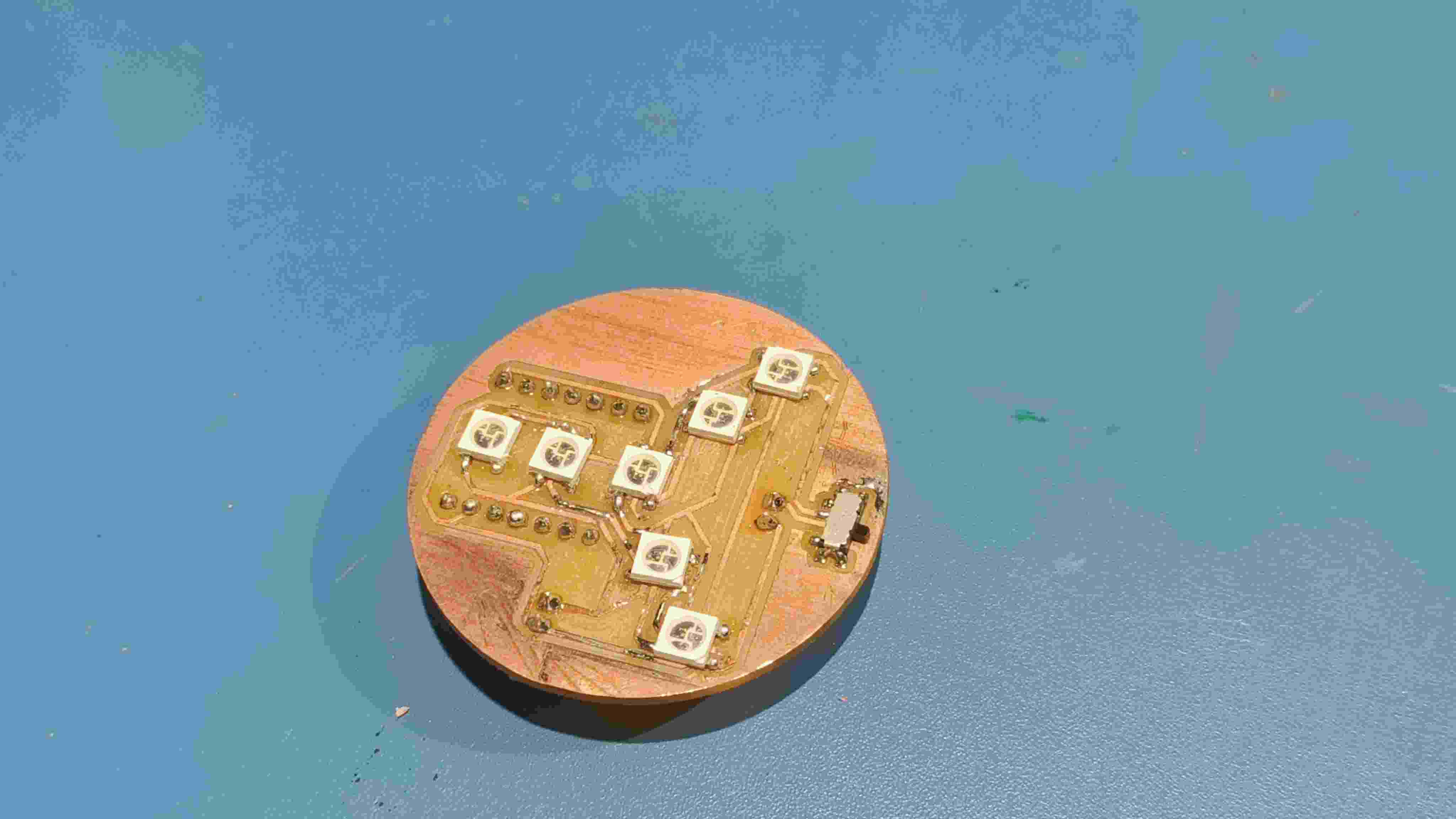
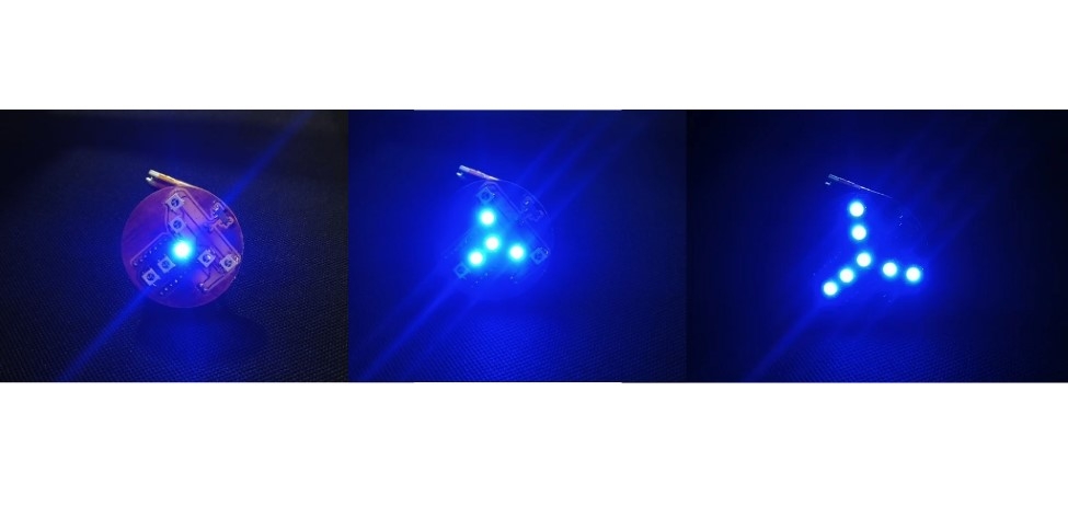
Making the PCB and mount of the LEDs
therefore 7 neopixels consumes : 7 x 60m A = 420mA
to find the battery consumption:
battery consumption =current x time it is left on
i.e. 420mA x 2 Hrs = 840mA
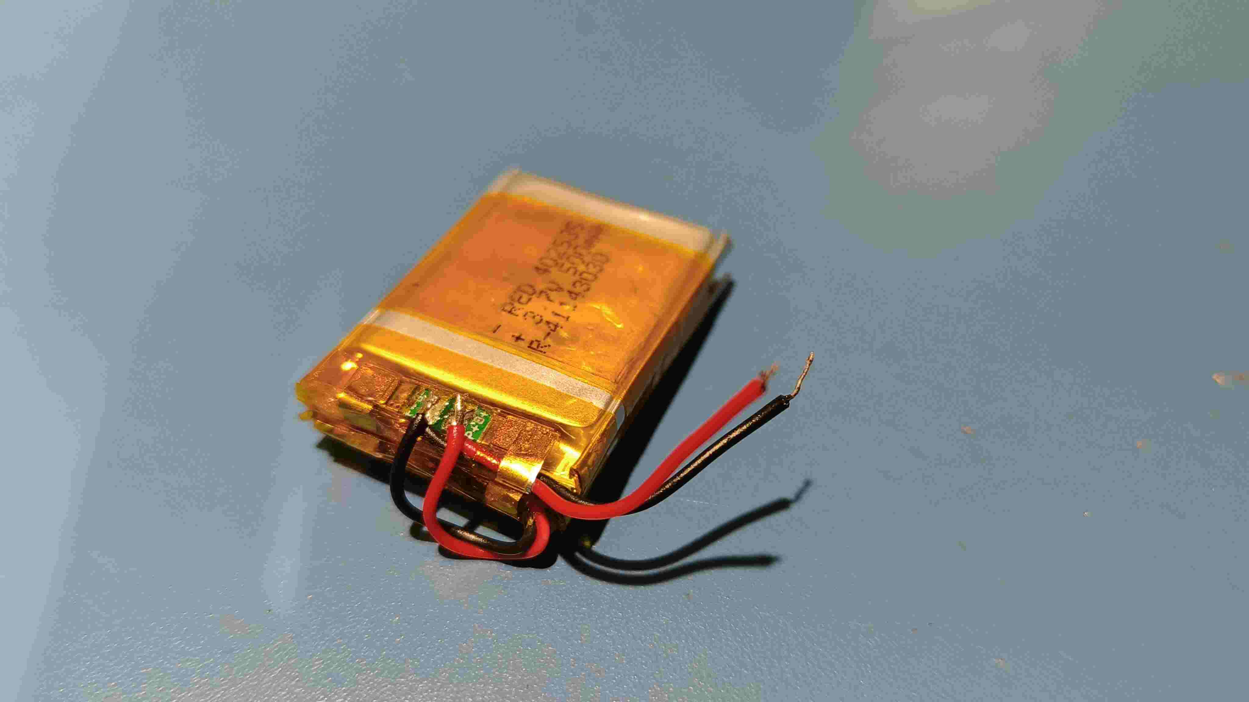
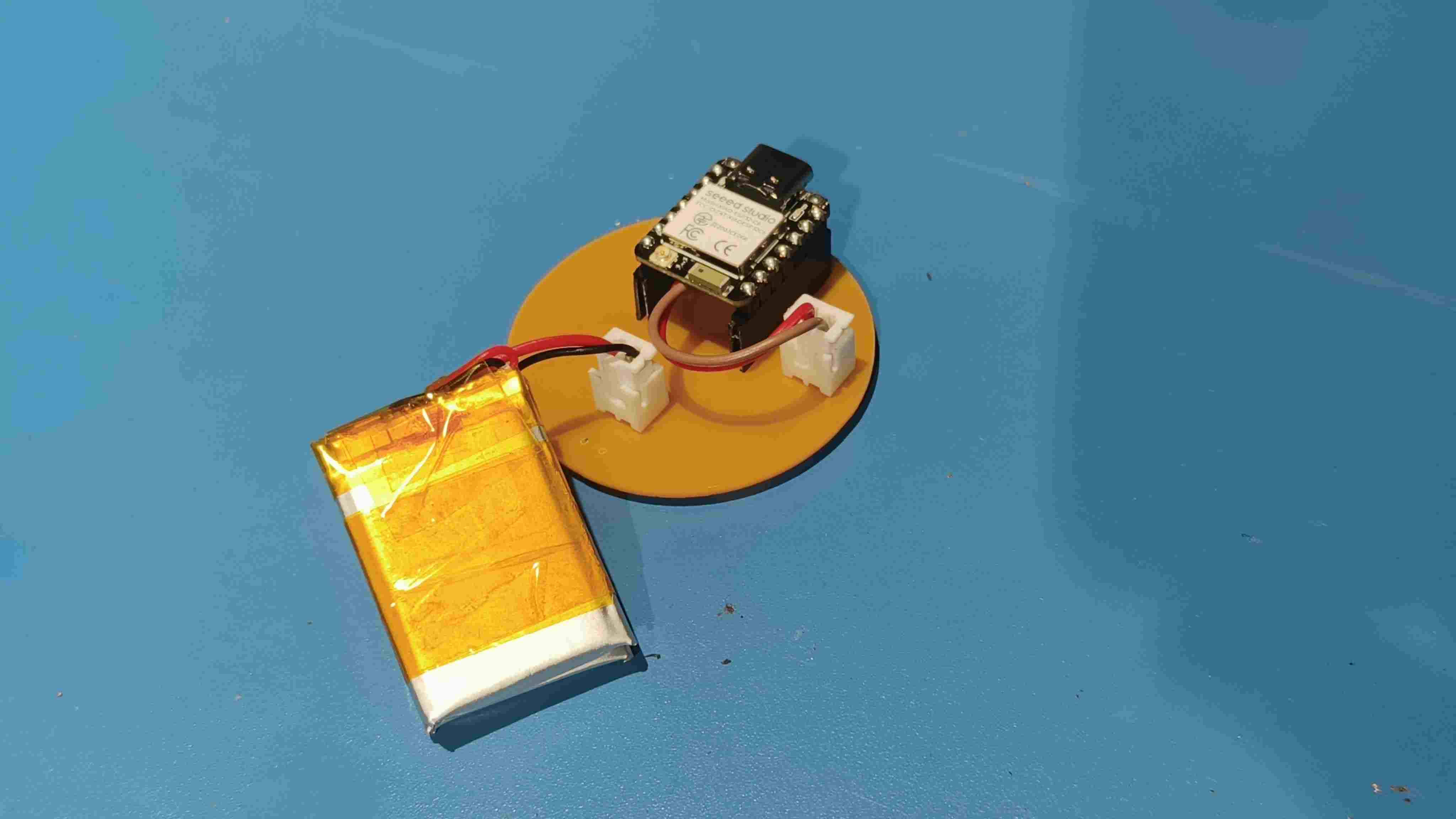
For the Battery
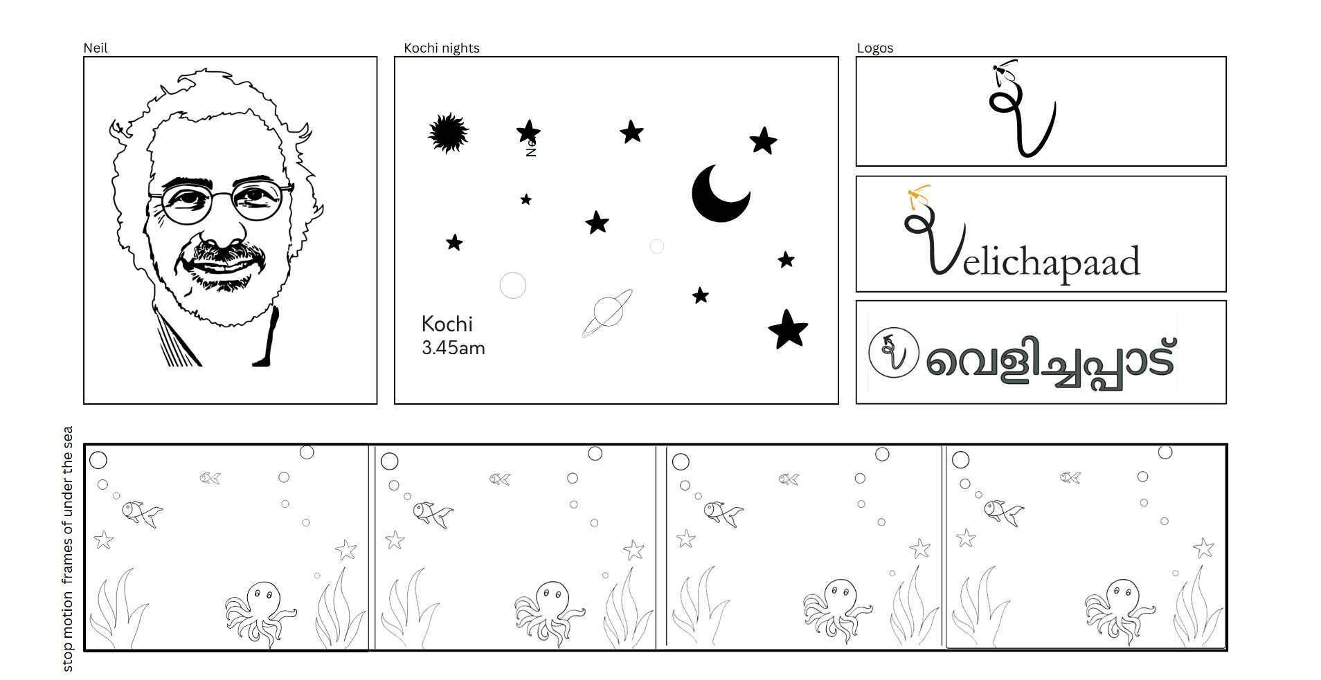
Branding and Logo

Presentation Slide
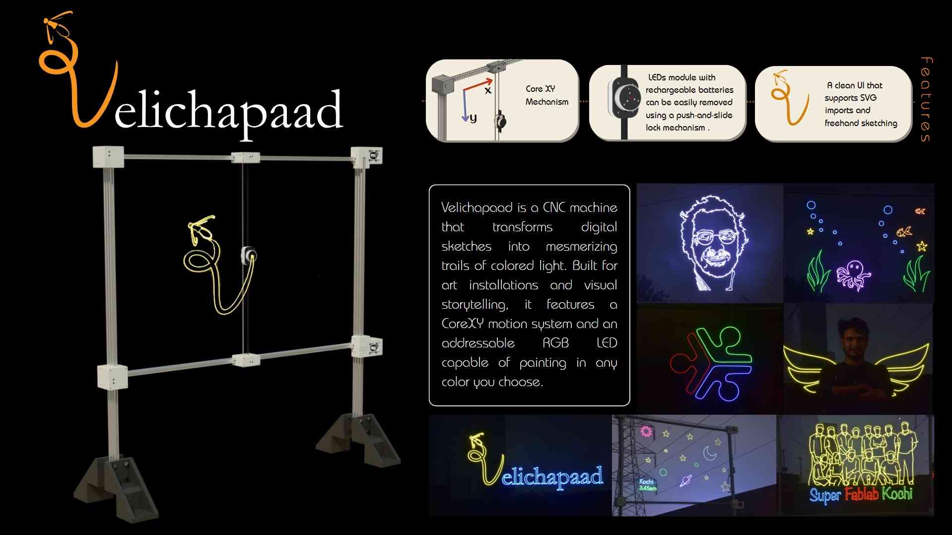
Graphics for Light Painting