7.COMPUTER CONTROLLED MACHINING
This week we learned how to use software and computer-controlled machinery to automate manufacturing processes
Group assignment:
Complete the lab's safety training
Test runout, alignment, fixturing, speeds, feeds, materials and toolpaths for your machine
Individual assignment:
To use an EDA tool to design a development board that uses parts from the inventory to interact.
GROUP ASSIGNMENT
You can view our group assignment here!
INDIVIDUAL ASSIGNMENT
Make something big!
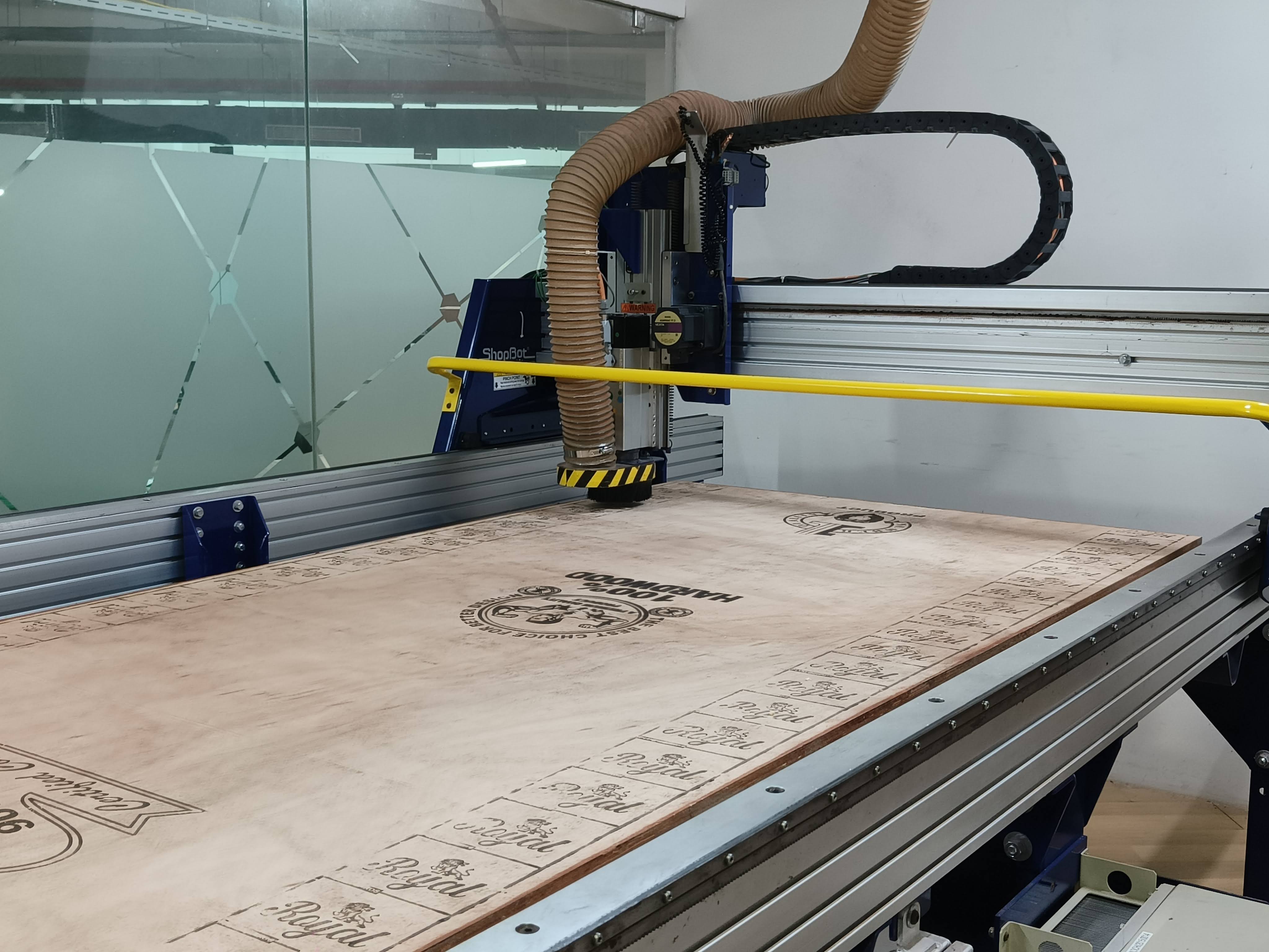
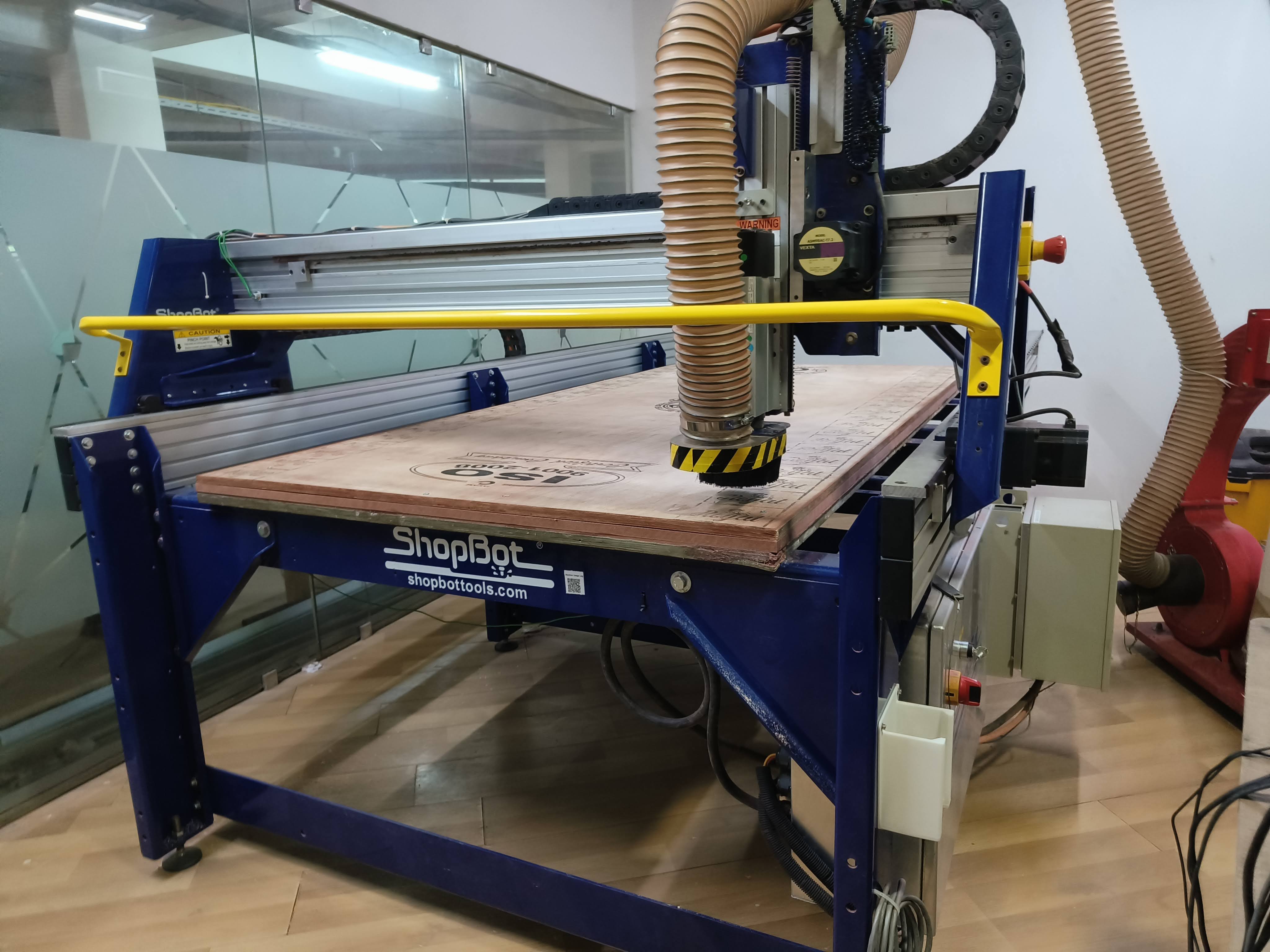
We were instructed to use Shopbot as our choice of machine and 8x4 plywood(18mm/12mm) as the material on which we
will make the product
![]()
Design
It took me a long while to figure out what to make. I have had prior experience in woodworking but that was
mostly
manual work. Using a CA machine to work on a project was new to me and it was quite challenging.
There were some limitations to what designs we could make from the machine such as time taken to create a piece
and
the dimensional constraints. Initially i was planning to make something with a lot of curved surfaces but
i did not go ahead with that since the risk of the furniture breaking were quite high.
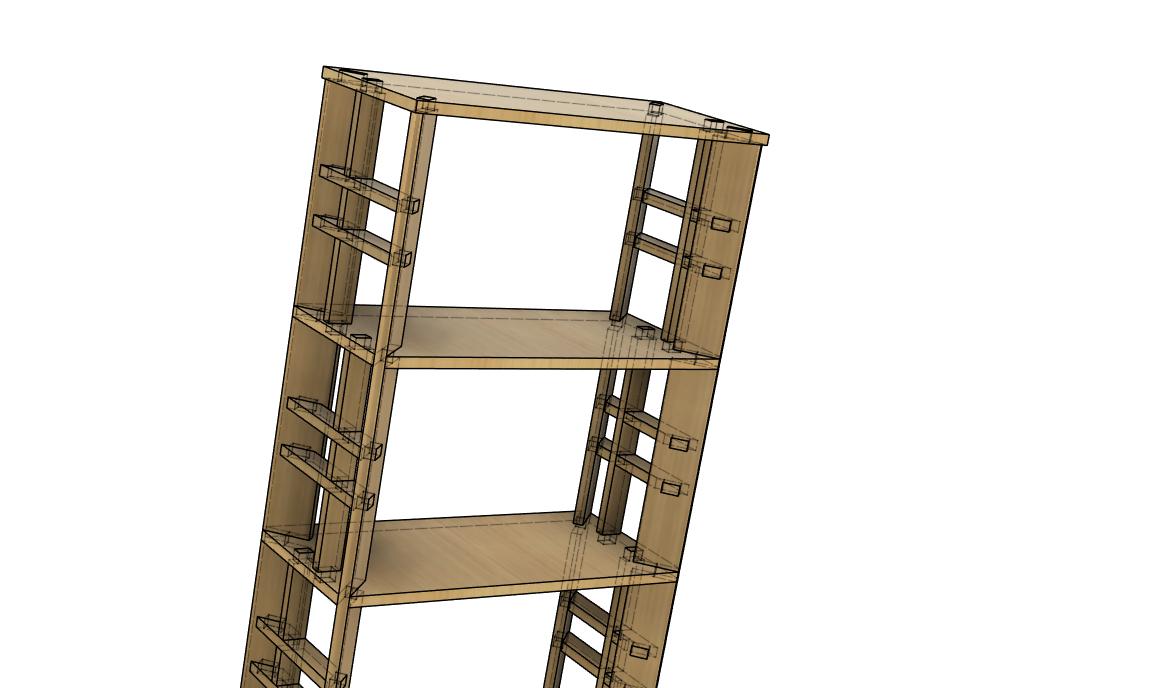
I wasn't as satisfied at first with the kind of design i was going for but was content as i went on to make more
customizations to the design. I went on to design a bookshelf as i wanted one to store my books, knickknacks and
display
music albums. I wanted the shelf to have some interlocking parts that would fit together like a puzzle.
I also wanted the shelves to be open rather than just making a box.
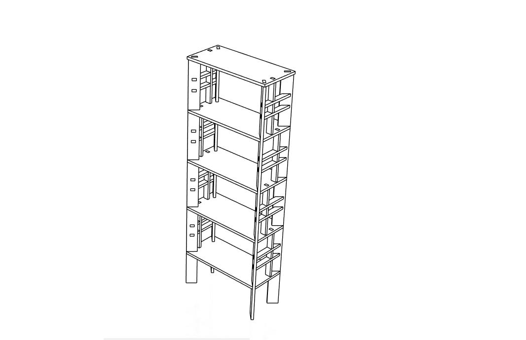
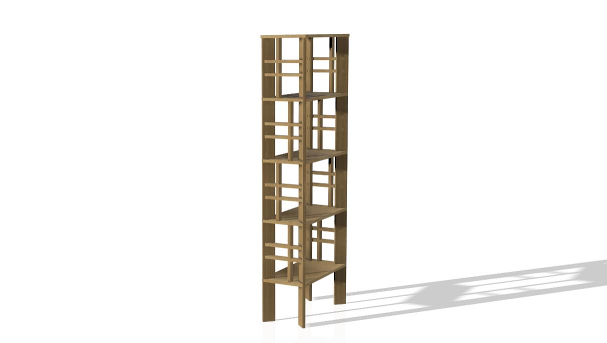
3DModel
This was the most frustrating and challenging part in the entire process for me. I had to make the entire shelf
as a
parametric design. Even though the design was simple enough adding constraints and variables took me a tedious
amount of
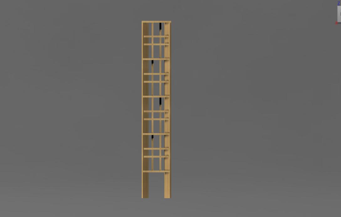
time to figure out. This was the first time i was trying to make the the entire furniture using parameters.
Adding to that my shelf contained a lot of parts that were made to enhance the locking and the looks.
As this is to be cut by the machine there wasn't any room for random errors. There were many many many changes
that were
gone through over and over again which made me feel defeated almost. Each time the model almost came together
there was
one small component causing a headache that would require me to completely dismantle the model and build it again.
Thankfully, my peers and instructors were extremely helpful and guided me through every roadblock. There are still
some issues that im trying to resolve where some of the parameters are not working properly. But as i am on
limited time
i had to move on after making an acceptable model where the thickness can be controlled which is the main
requirement
for cutting on the machine.
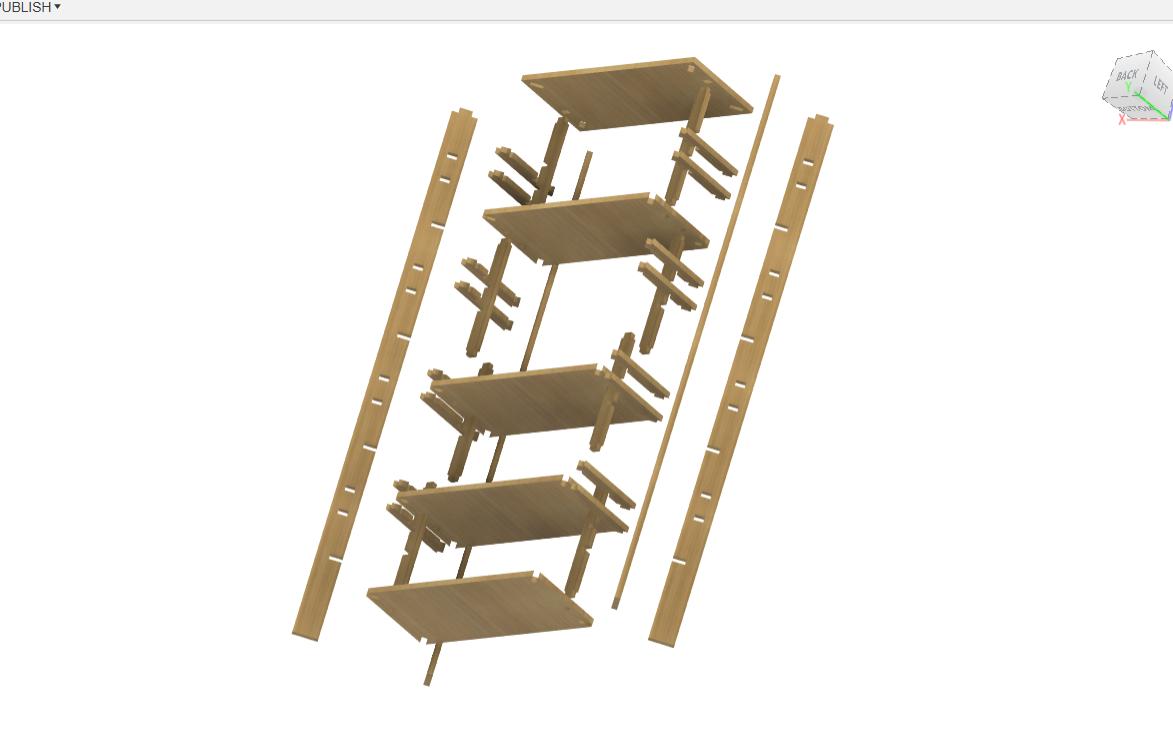
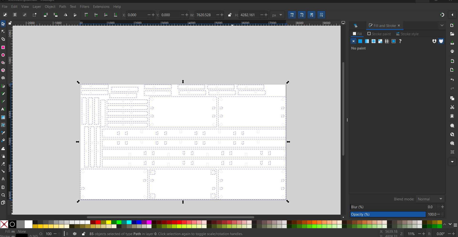
Cardboard Mockup
We were instructed to make a scaled down mockup of the design on cardboard to check the proportions and see
how the fit will look like. Using the "arrange" function in Fusion360 to place all the components spread out on
a plane. Then we project the components on a sketch plane which we will be required to export as a dxf file.
Open this dxf file on inkscape . To scale down the model we need to find the ratio of the features .
We know the the width to be 18 and height was 1521, we need it to change to 3 width and using ratio calculator
the height came to me 15853 . Resize the the sketch and turn the stroke colour to red ,to denote the cutline.
Save the sketch as a svg file.
 Now open the job control app and import the svg file we just created. snap the
laser pointer to snap to the sketch. Check the database and see if all the values are correct.
Place the cardboard on the print bed and align the origin point. After setting up everything start the process.
Now open the job control app and import the svg file we just created. snap the
laser pointer to snap to the sketch. Check the database and see if all the values are correct.
Place the cardboard on the print bed and align the origin point. After setting up everything start the process.
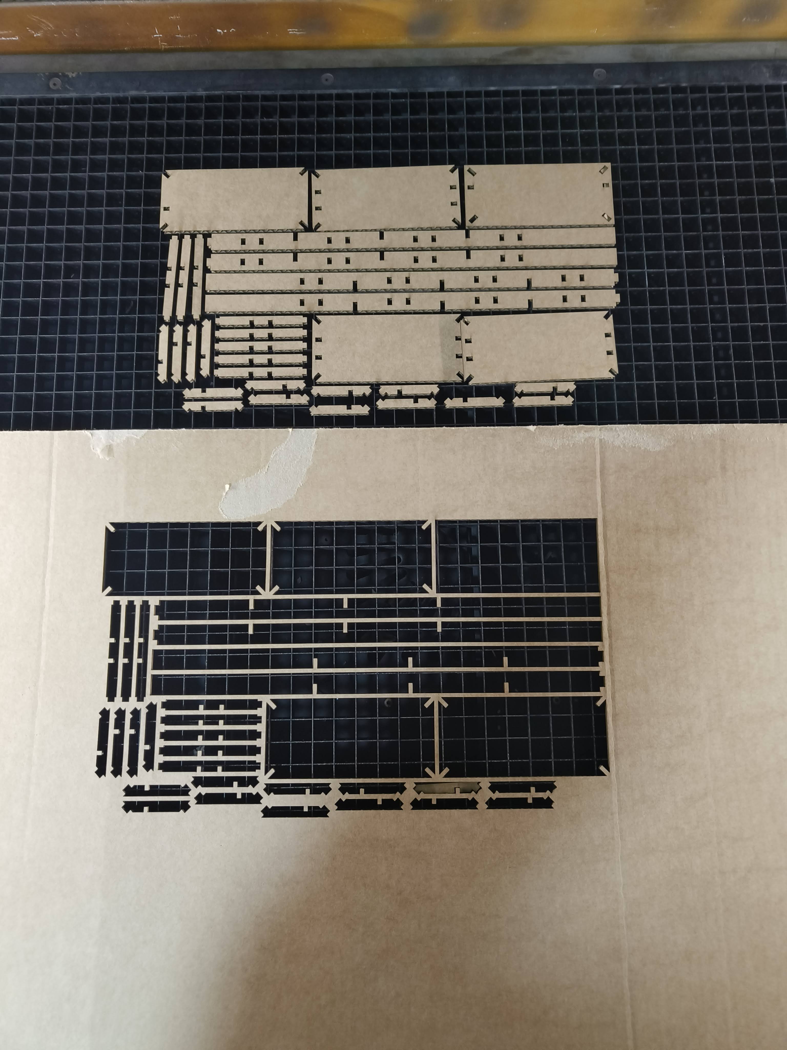
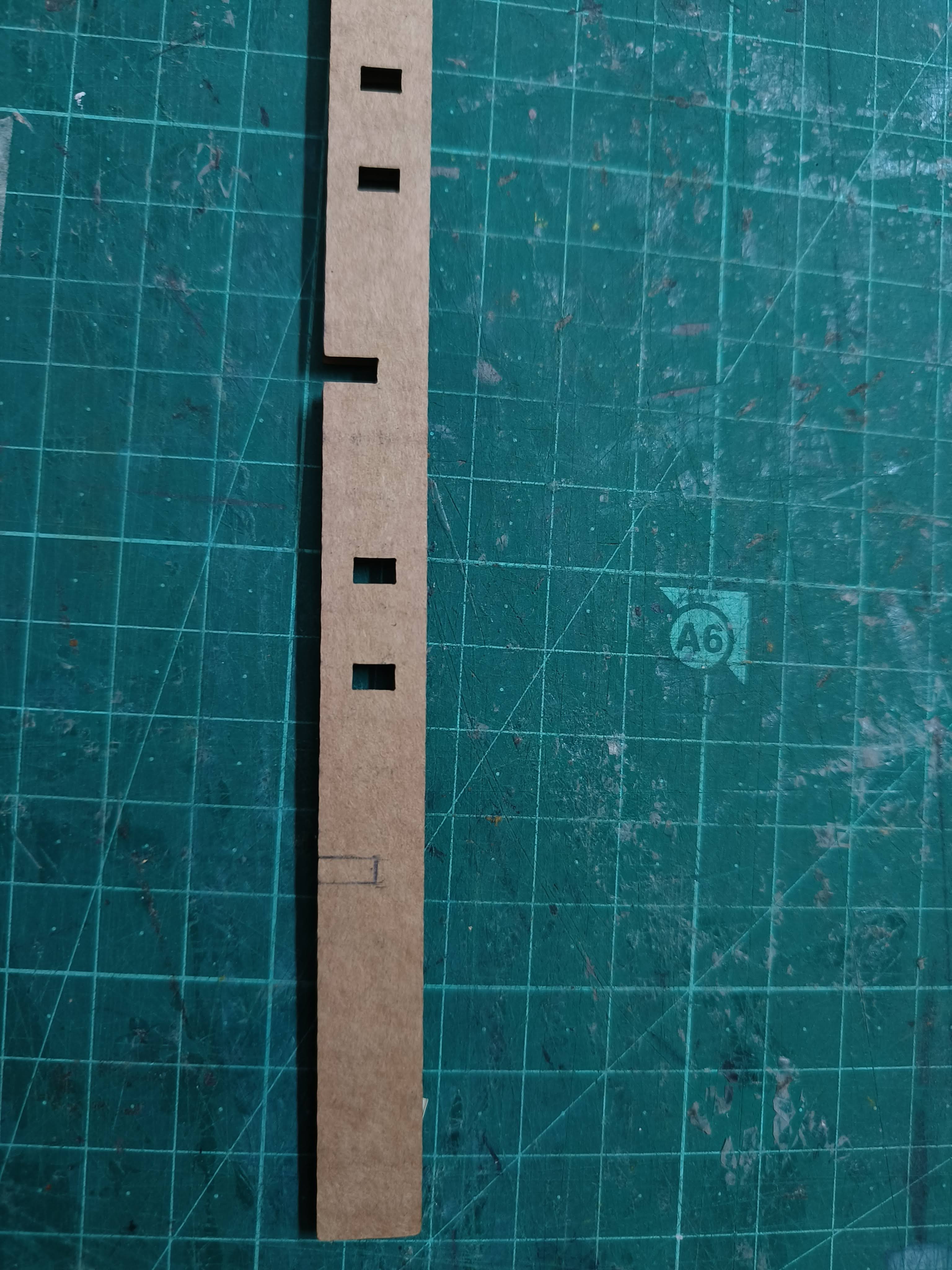
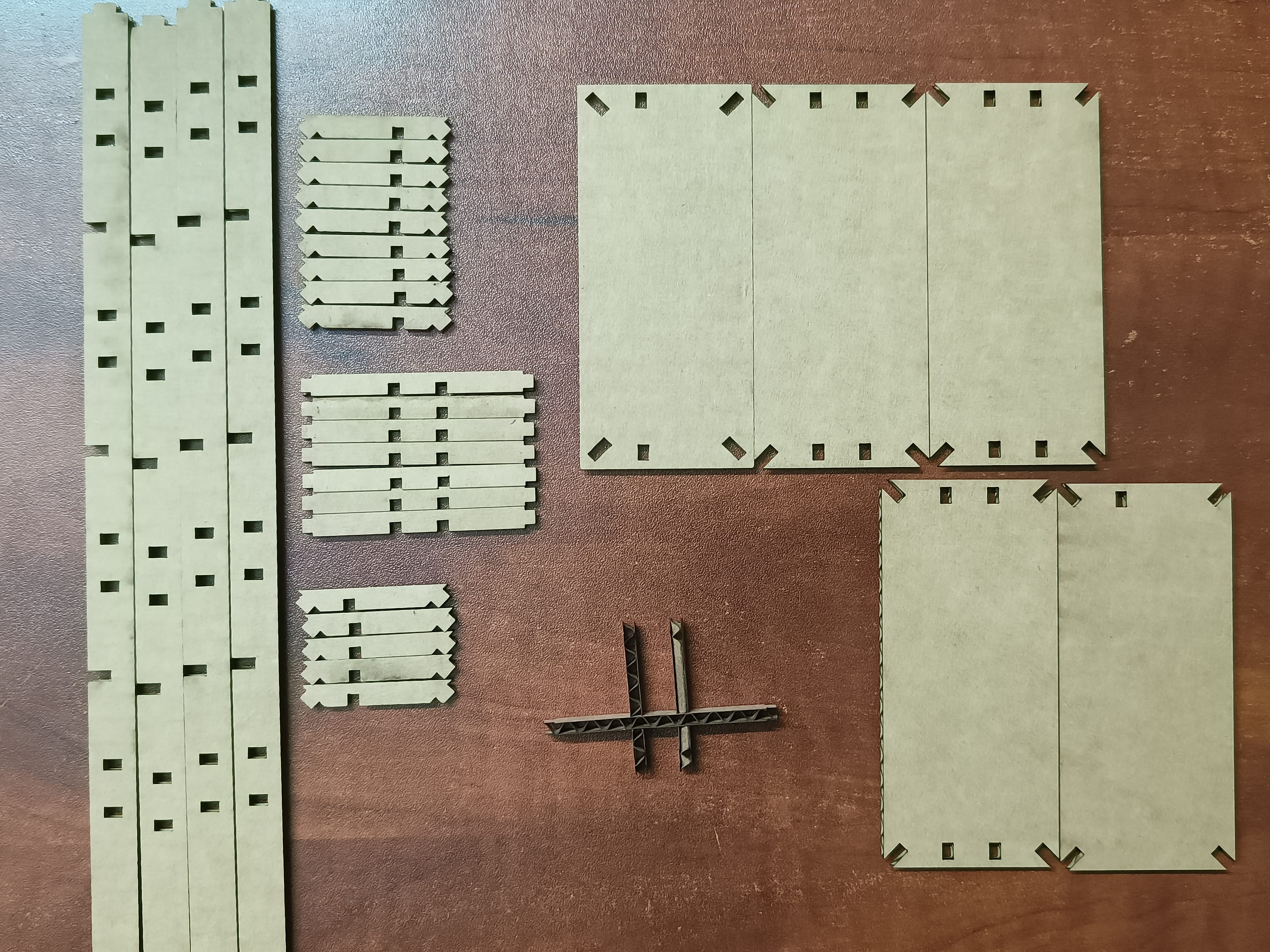 Once the cut is done i started to sort and assemble the pieces. Some pieces of the cardboard bent a
little because of the orientation they were cut in. Also i noticed that some slots were missing on the pieces so
i went back to the model and checked, There seemed to be some parts that were uncut, which i resolved
immediately.
For the time being and since it was only a minor mistake i cut the slots using a exacto and measuring the
distances
properly.
Once the cut is done i started to sort and assemble the pieces. Some pieces of the cardboard bent a
little because of the orientation they were cut in. Also i noticed that some slots were missing on the pieces so
i went back to the model and checked, There seemed to be some parts that were uncut, which i resolved
immediately.
For the time being and since it was only a minor mistake i cut the slots using a exacto and measuring the
distances
properly.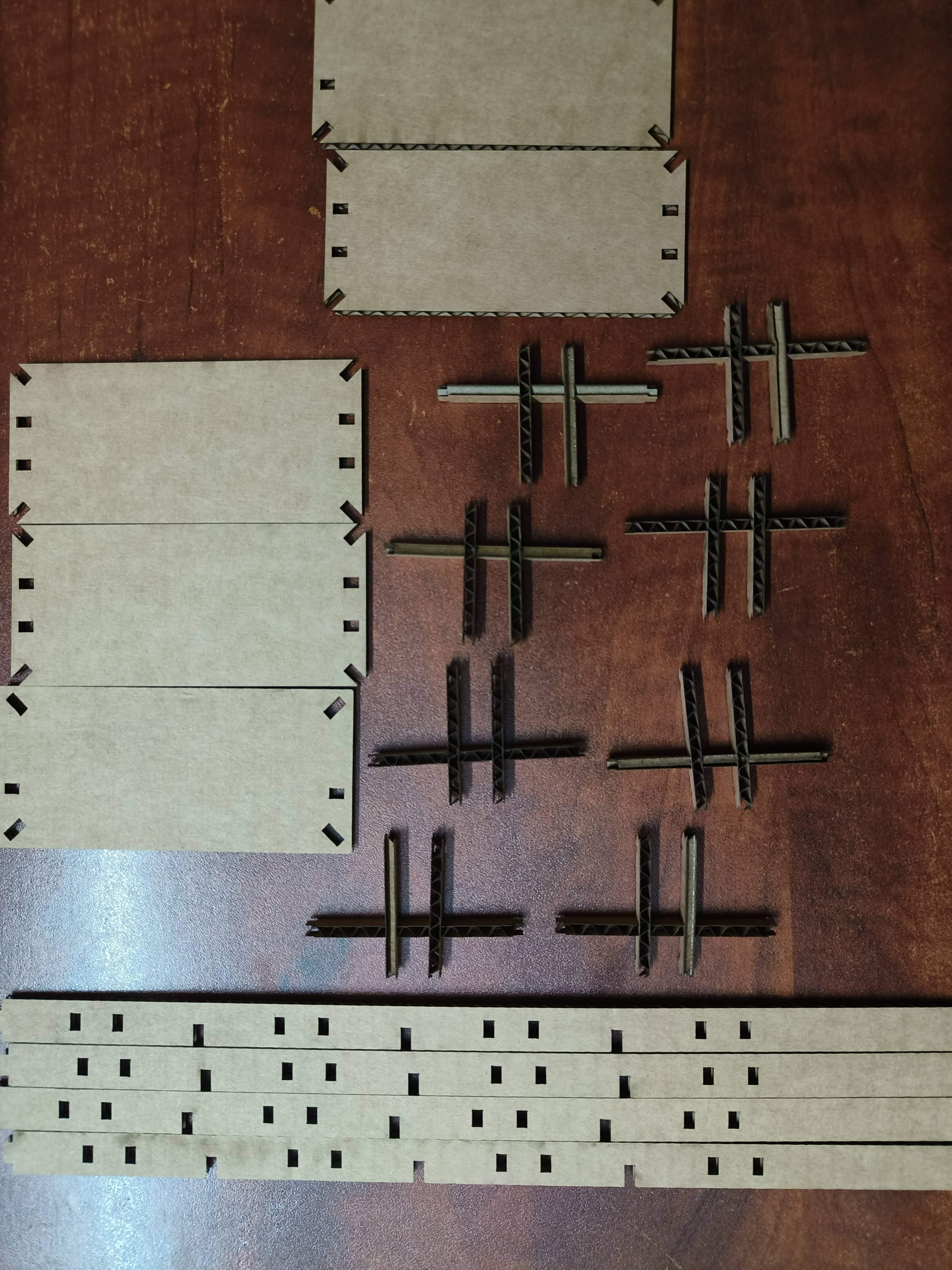
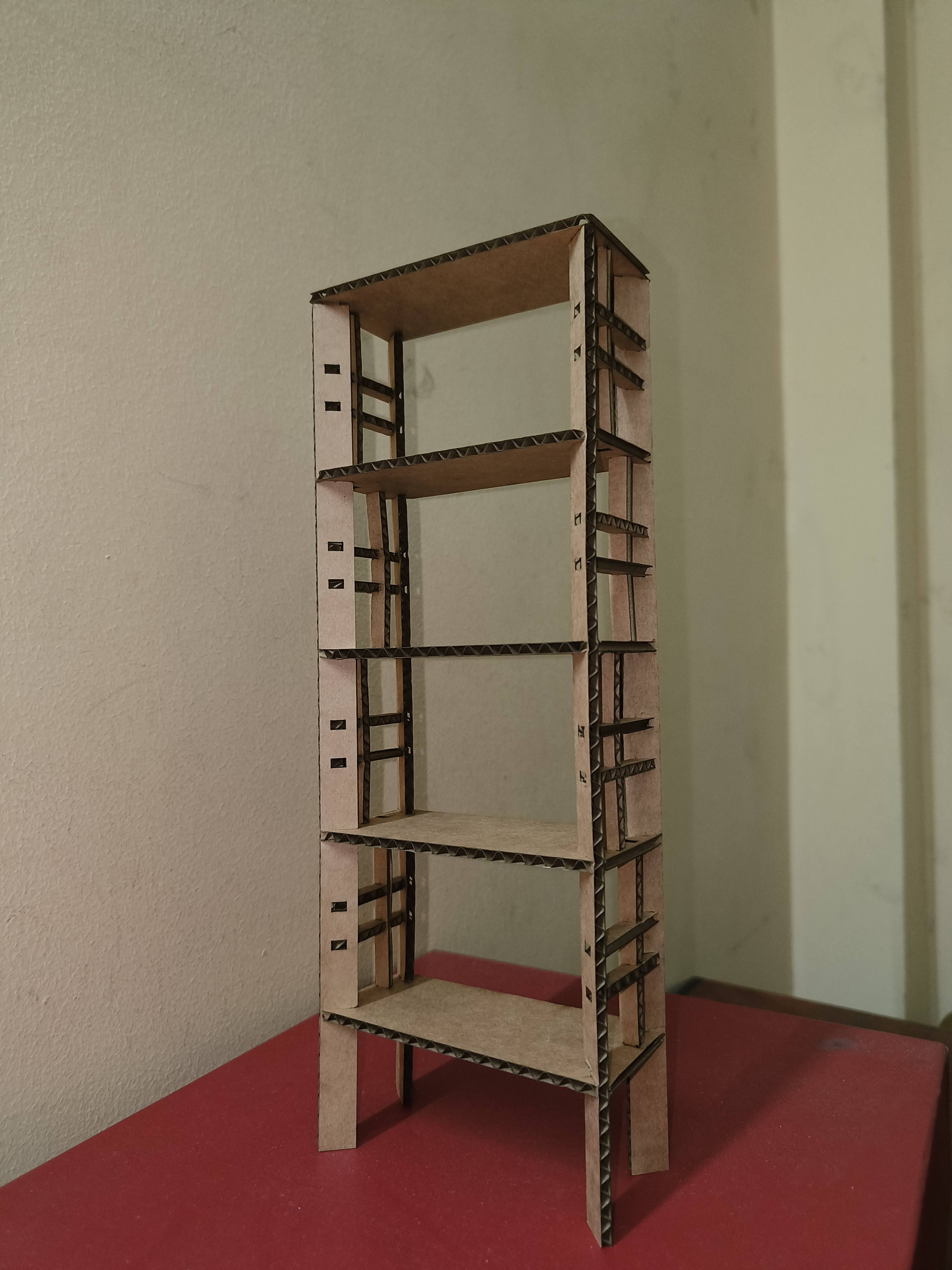
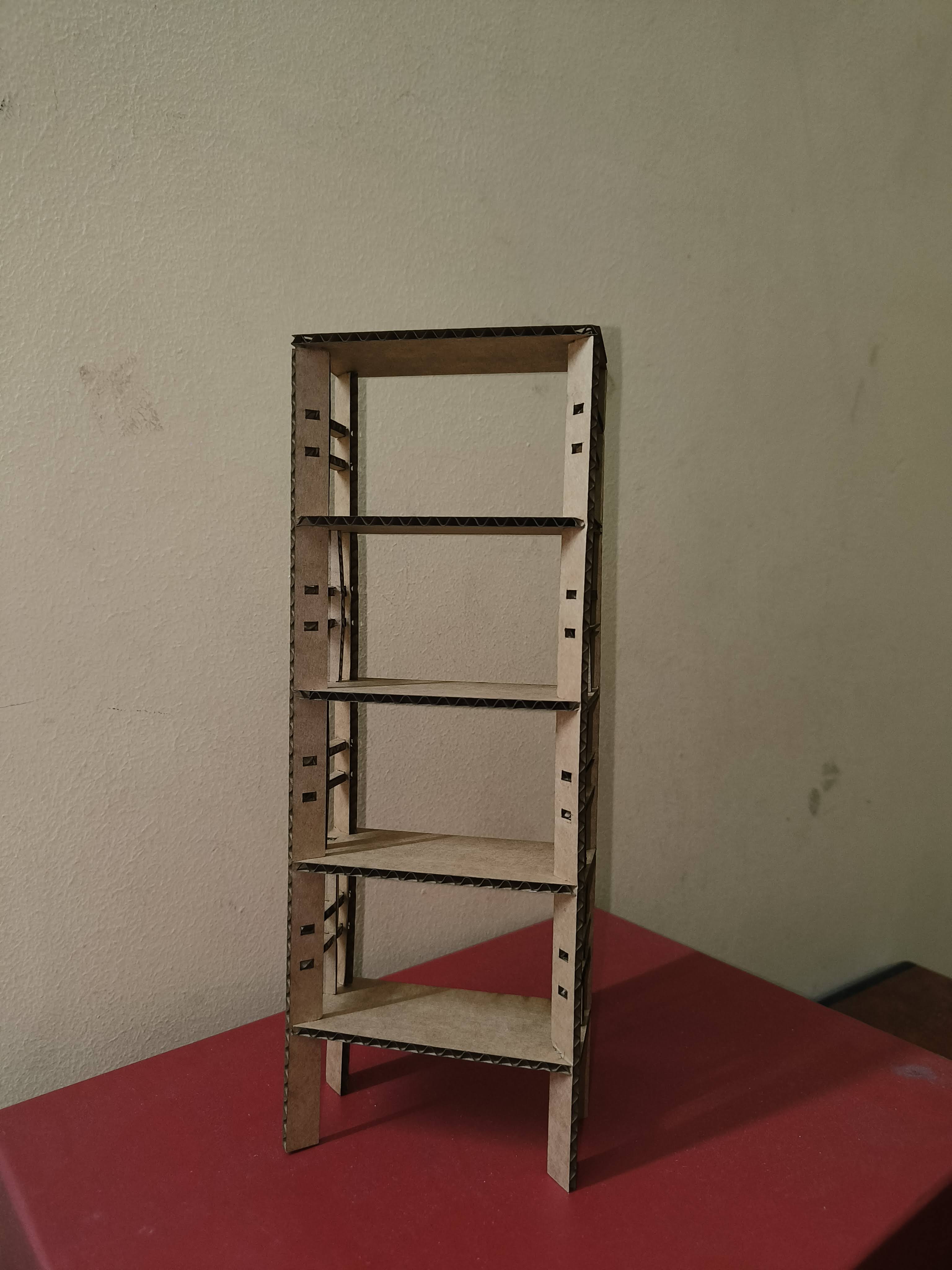
I was quite satisfied with the fit and held up better than i thought while modelling.
I also was able to figure out how to assemble the parts efficiently as well.
Preparing the Job
Before taking the plywood to the machine ,we need to check the thickness of the piece as it will affect the
overall
dimensions of the furniture. I measred the thickness of the plywood with a vernier calliper and found out that the
average thickness of the piece i was given was 17.2mm.
As i had made the model with a thickness of 18mm i had to change the scale of the model.
I also had to take into account the offset value from the machine that turned out to be 0.2mm ,
which we concluded in the group assignment. The dimensions were changed accordingly.
Once this was done we proceeded to start the machine operations.
CAM
Using VCarve
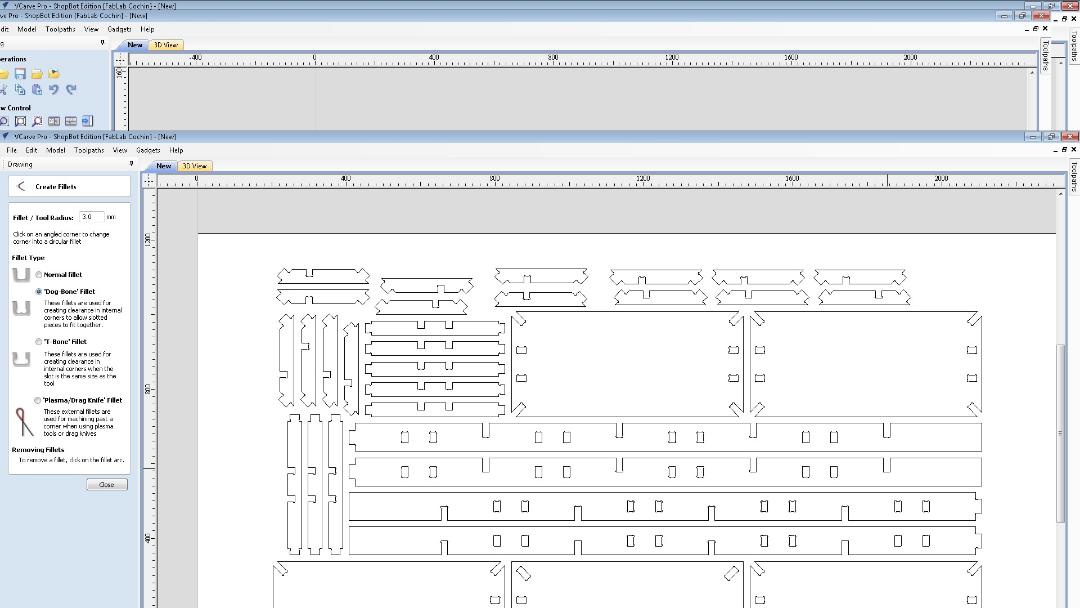
We need to define the toolpaths, add dogbones and tabs to the drawing so that the machine can cut them
accordingly.
VCarve provides a powerful but intuitive software solution for creating and cutting parts on a CNC router.
The following steps were followed to make the cutting parts.
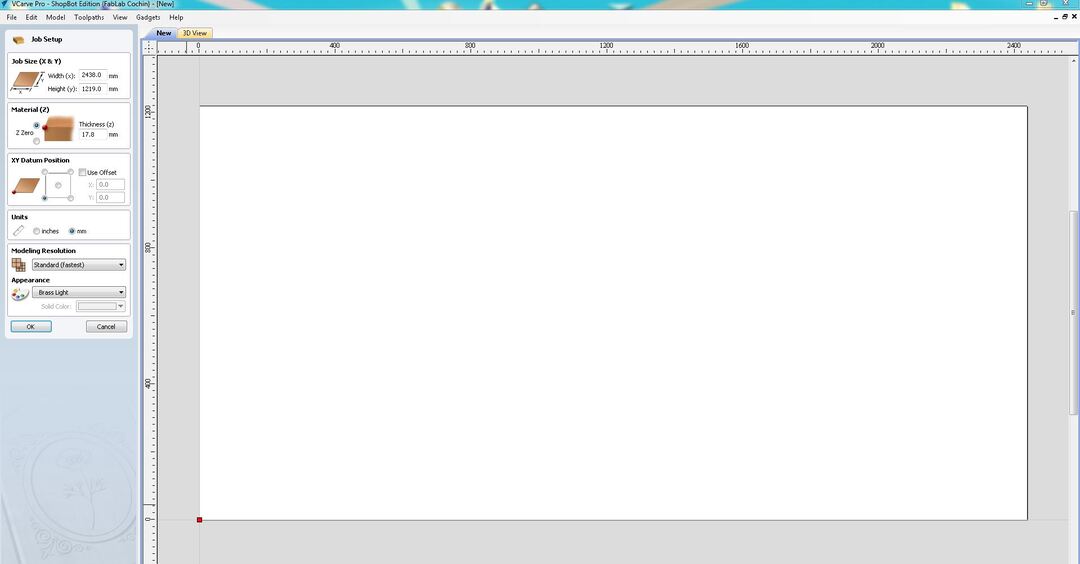
Go to 'Create a new file' to make a new file . Set the stock size(X,Y,and Z) of the workpiece keeping the unit
in mm.
 Next we import the .dxf file.To do so go to File>> Import >> Import Vectors.
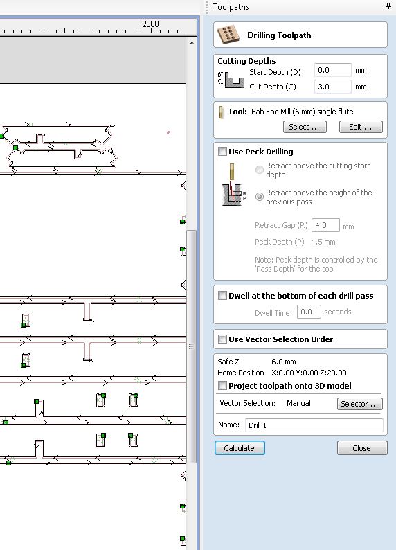
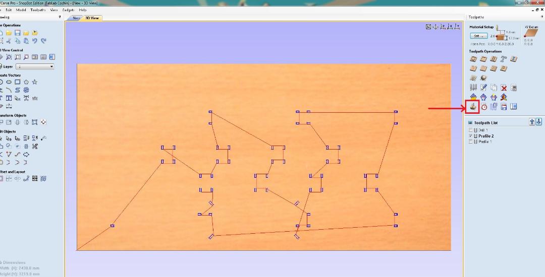
Reference point for drilling: We are supposed to drill the work piece on to the sacrificial layer so that it
stays in place. If we blindly drill holes in random areas of the the job there is a chance that the screw may
coincide with the toolpath. To avoid this from happening we run a drill path to mark refrence points for
screwing the piece down. Create a few circles and place them on the edges where the paths dont meet.
Next we import the .dxf file.To do so go to File>> Import >> Import Vectors.
Reference point for drilling: We are supposed to drill the work piece on to the sacrificial layer so that it
stays in place. If we blindly drill holes in random areas of the the job there is a chance that the screw may
coincide with the toolpath. To avoid this from happening we run a drill path to mark refrence points for
screwing the piece down. Create a few circles and place them on the edges where the paths dont meet.
To do this we select the drill toolpth and set the drill points where there is a gap between the pieces.
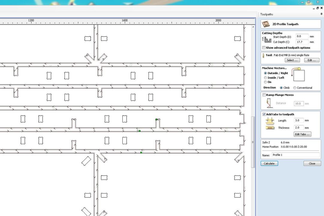
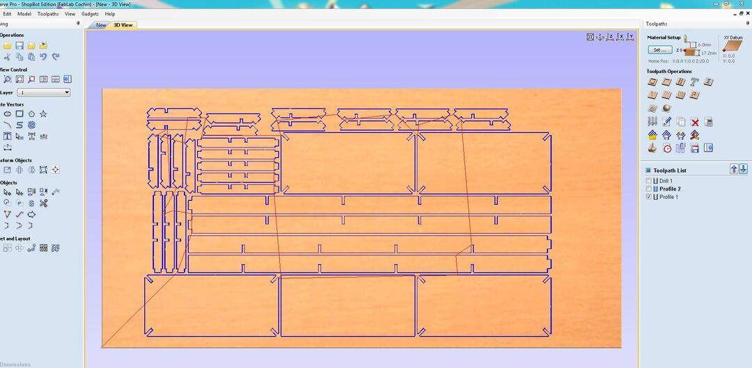
 Next we define the toolpath for the inside features of the pieces. I chose 2d profile toolpath and then set
the
Cutting depths, Tool, Passes and Cut direction. Then Click on Calculate to generate the tool path.
Next we define the toolpath for the inside features of the pieces. I chose 2d profile toolpath and then set
the
Cutting depths, Tool, Passes and Cut direction. Then Click on Calculate to generate the tool path.
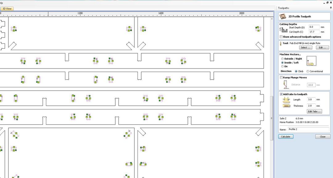 Now we set the toolpaths for the outer features. Set the Cut depths, Tool, Compensation left or right and
Create tabs . Again click calculate to generate the path.
Now we set the toolpaths for the outer features. Set the Cut depths, Tool, Compensation left or right and
Create tabs . Again click calculate to generate the path.
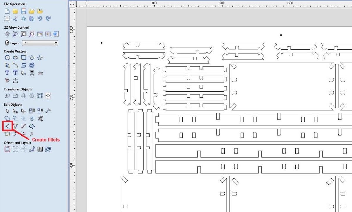
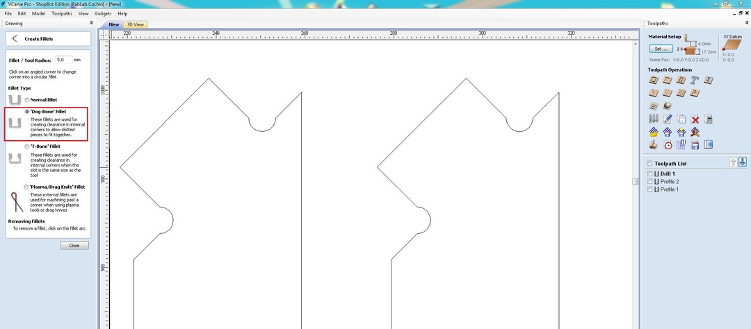
 Dogbones : Dogbones are made to give a good fit between the inner edges of slots. I added dogbones on all of
my slots and edges.
Dogbones : Dogbones are made to give a good fit between the inner edges of slots. I added dogbones on all of
my slots and edges.
Tabs: Tabs are added to give support to the cut parts which may move and cause issues when the tool . It can be
quite dangerous if the tabs are not given appropriately.
You can see the simulation of the tool going across the toolpaths created by clicking on preview toolpath.
Once the drill path and the toolpaths are given we can proceed to the operations.
The entire operation process has been explained in detail in th e group project.
First we run the drill path and mark the points to be screwed. Stop the machine and screw in the job to the
sacrifcial board.
Then we can start the cutting process of the parts.
Load the program to the machine's software by using the Cut Part option.
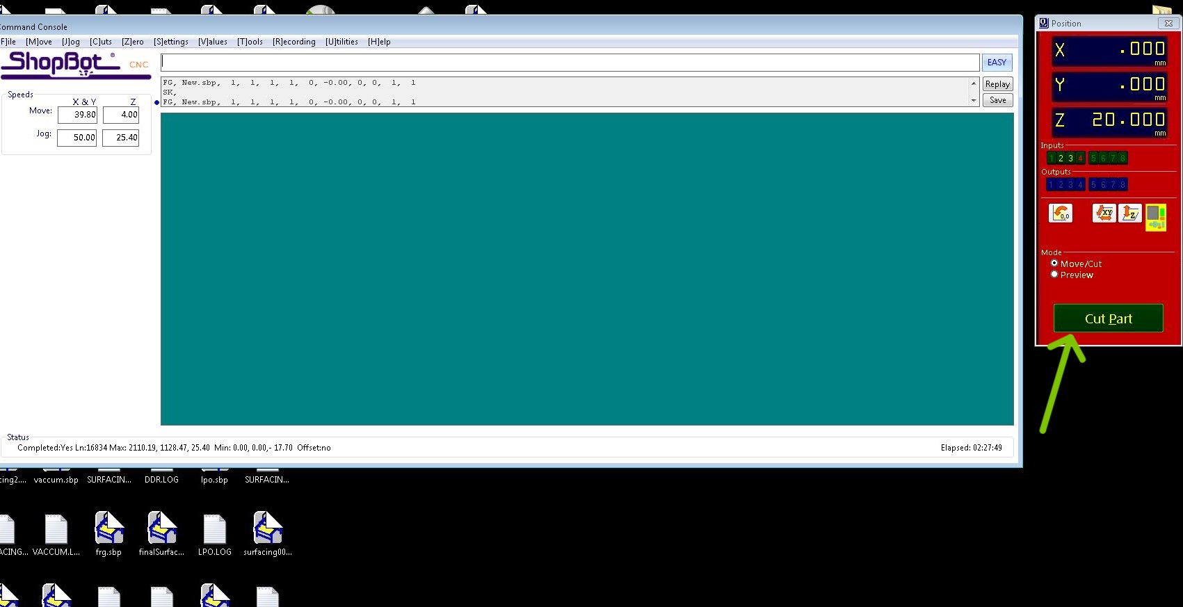 Click on Start and a dialogue box appears prompting to turn ON the spindle.Click OK. Using the Spindle start
switch the spidle turns on and then wait for a few seconds for the RPM to stabalize.
The machine started to run the operations
Click on Start and a dialogue box appears prompting to turn ON the spindle.Click OK. Using the Spindle start
switch the spidle turns on and then wait for a few seconds for the RPM to stabalize.
The machine started to run the operations
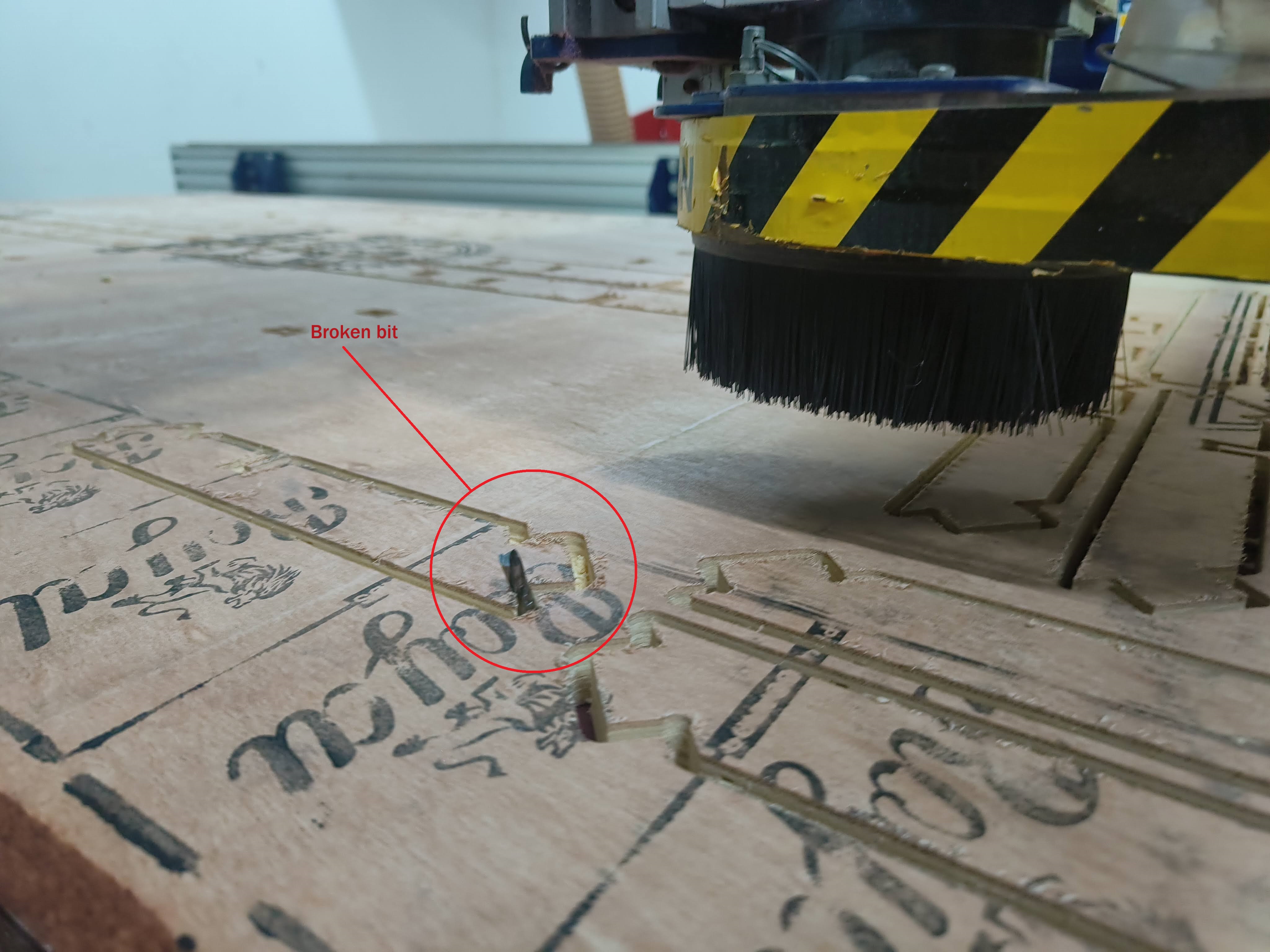
Unfortunately the bit broke twice during the cutting process and i had to halt my work for the time being until
we can resolve the issue.
After replacing the bit ,we had to do the z-leveling again and also take the tool back a few steps to run over
again to get a
proper cut as we dont exactly know where the bit broke. To do this we use the Go to line command from File.
The value that was on the screen when we pressed the emergency button was around 10400 so I entered the value to
the go to line was 10100.
Then click on Run to. The machine jogs to that point.O nce it reaches the positon we can click the start
operation again.
Luck was not my side this week as the tool bit broke again when the machine reached the same area where the
tool broke last time. We took out time to figure out why this was happening
but could not find a definitive answer(it probably could be something in between the layers of the ply, but
cannot conclude this.)
 Finally after some help from our fablab instructors and technicians i was able to finish the cutting process
on the machine. But the week was done by then and had to come back to the project later.
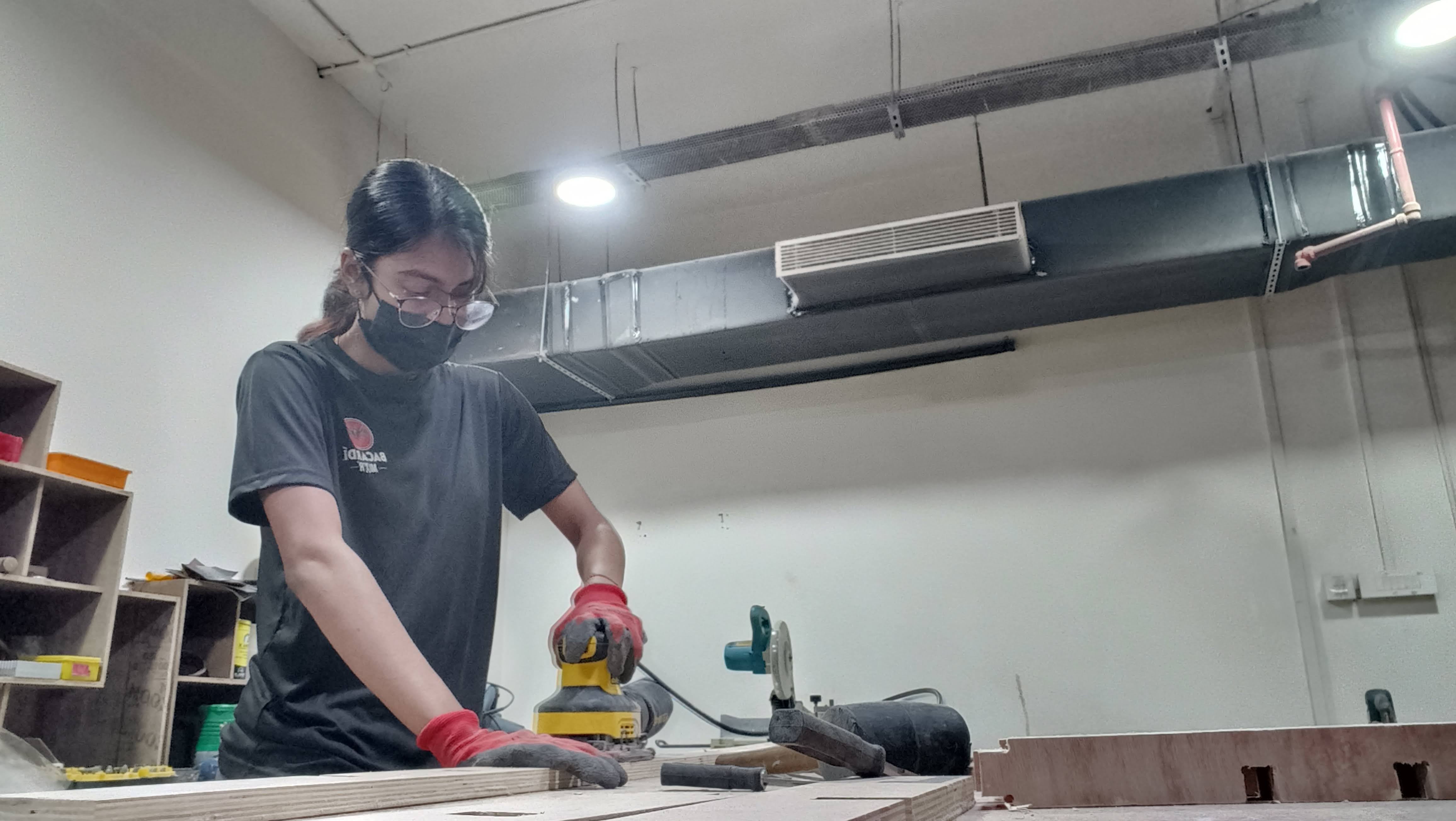
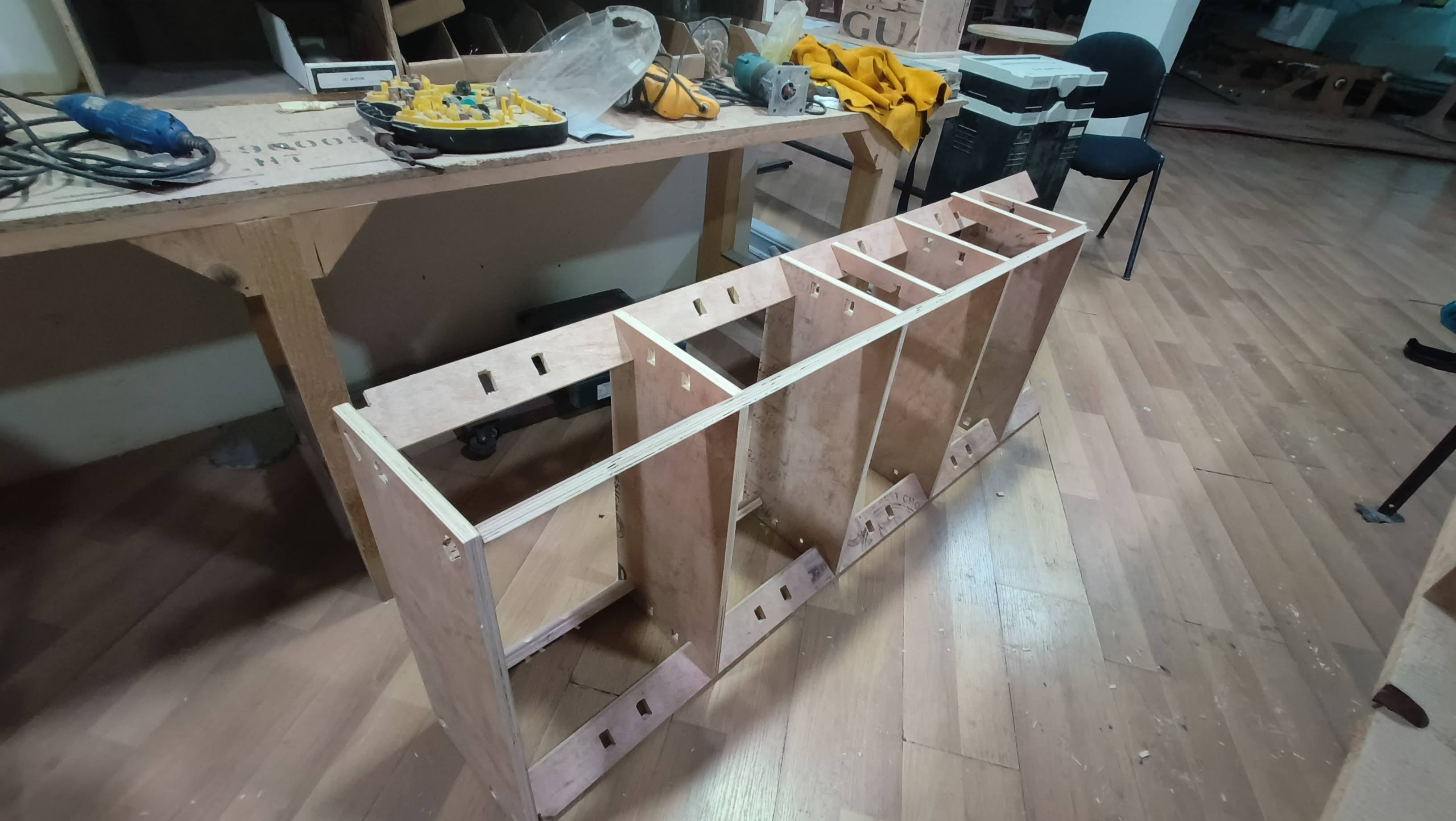
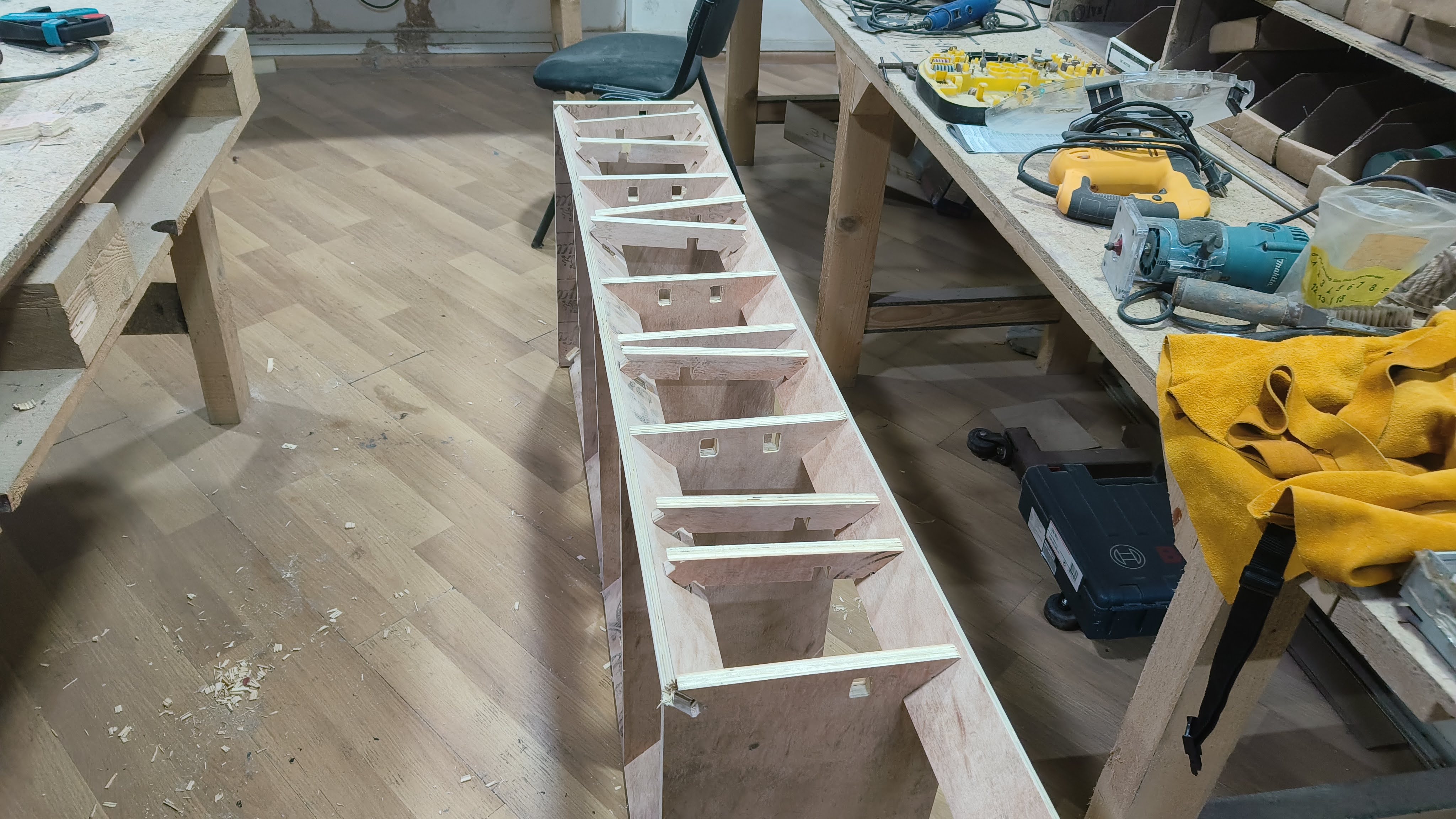
After a few weeks i went back to the project to complete it.I had to first clean up the pieces by sanding the
rough cuts and also remove the tabs.
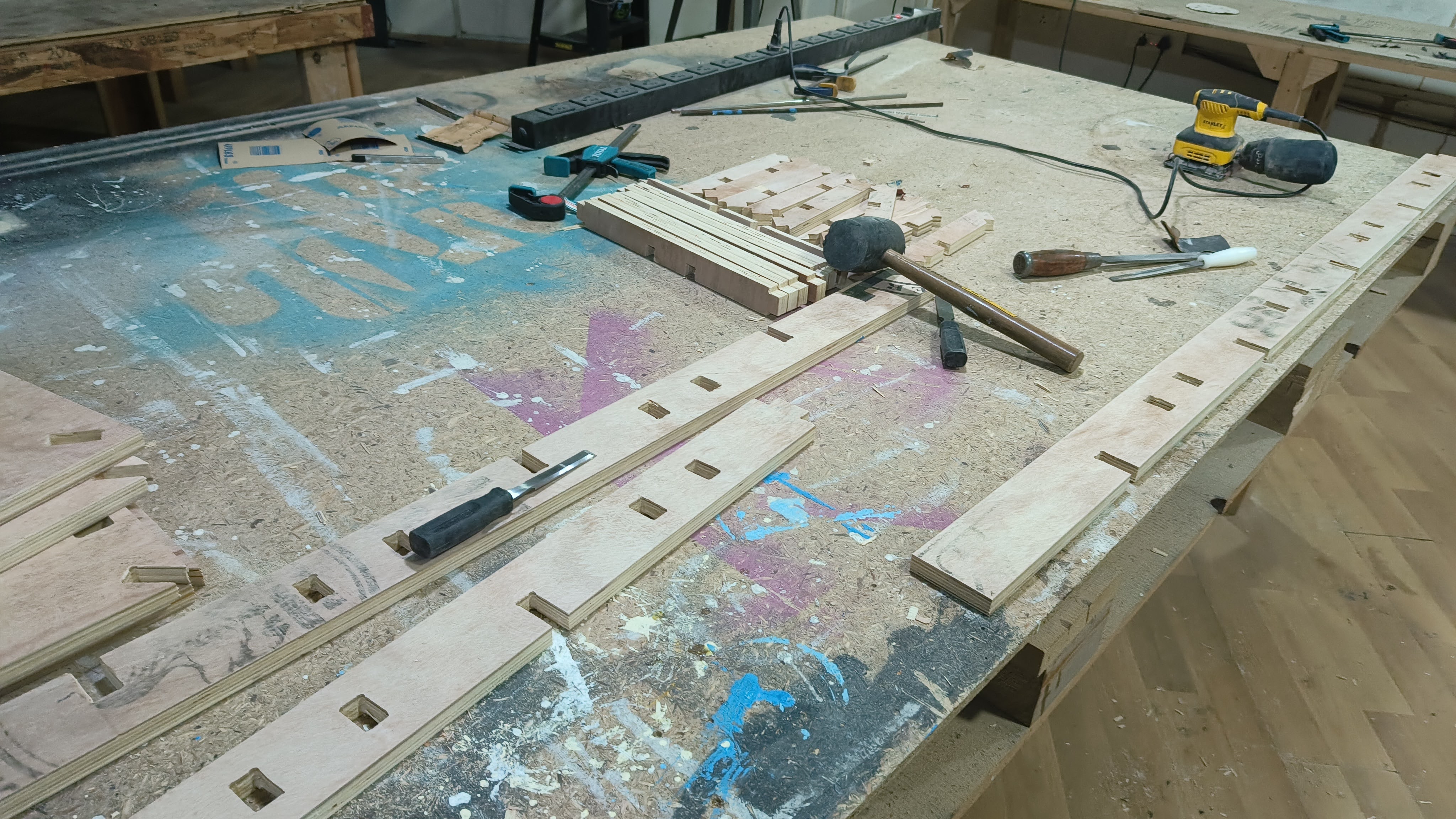
I also had to chisel out the slots made by the machine as some did not turn out right and was uneven.
Finally after some help from our fablab instructors and technicians i was able to finish the cutting process
on the machine. But the week was done by then and had to come back to the project later.
After a few weeks i went back to the project to complete it.I had to first clean up the pieces by sanding the
rough cuts and also remove the tabs.
I also had to chisel out the slots made by the machine as some did not turn out right and was uneven.
 The lengths of the cross bars had to be shortened because it wasn't fitting in between the frames easily.
Probably if the slots were a little more looser for all the joints it would have been an easier assembly
process without much alterations. Everything was very tight, which brought complications for assembling the
entire shelf
I also had adjust the the widths of the slots at some places. Chiseling took a big chunk of my time for this
project.
The lengths of the cross bars had to be shortened because it wasn't fitting in between the frames easily.
Probably if the slots were a little more looser for all the joints it would have been an easier assembly
process without much alterations. Everything was very tight, which brought complications for assembling the
entire shelf
I also had adjust the the widths of the slots at some places. Chiseling took a big chunk of my time for this
project.
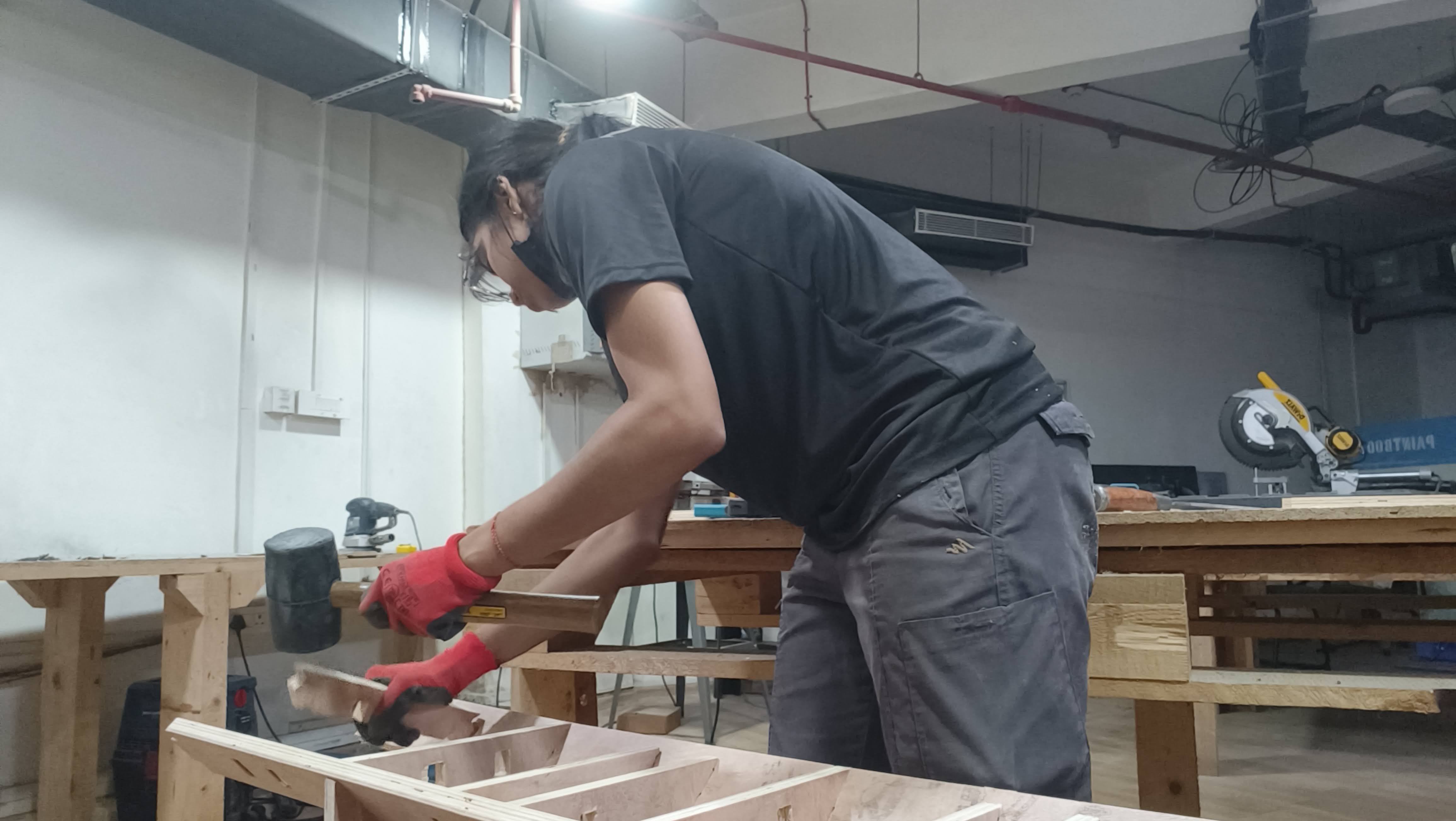
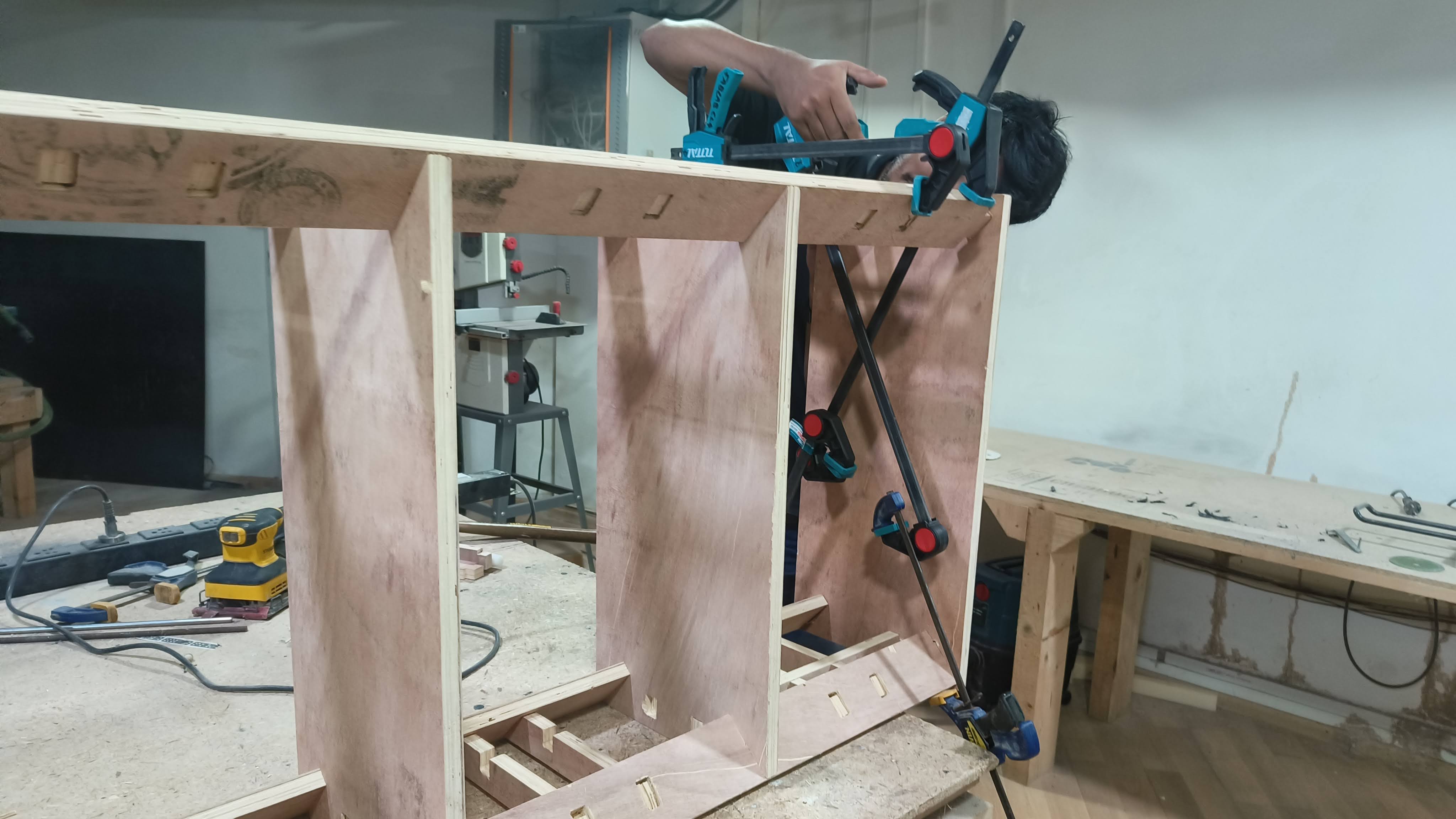
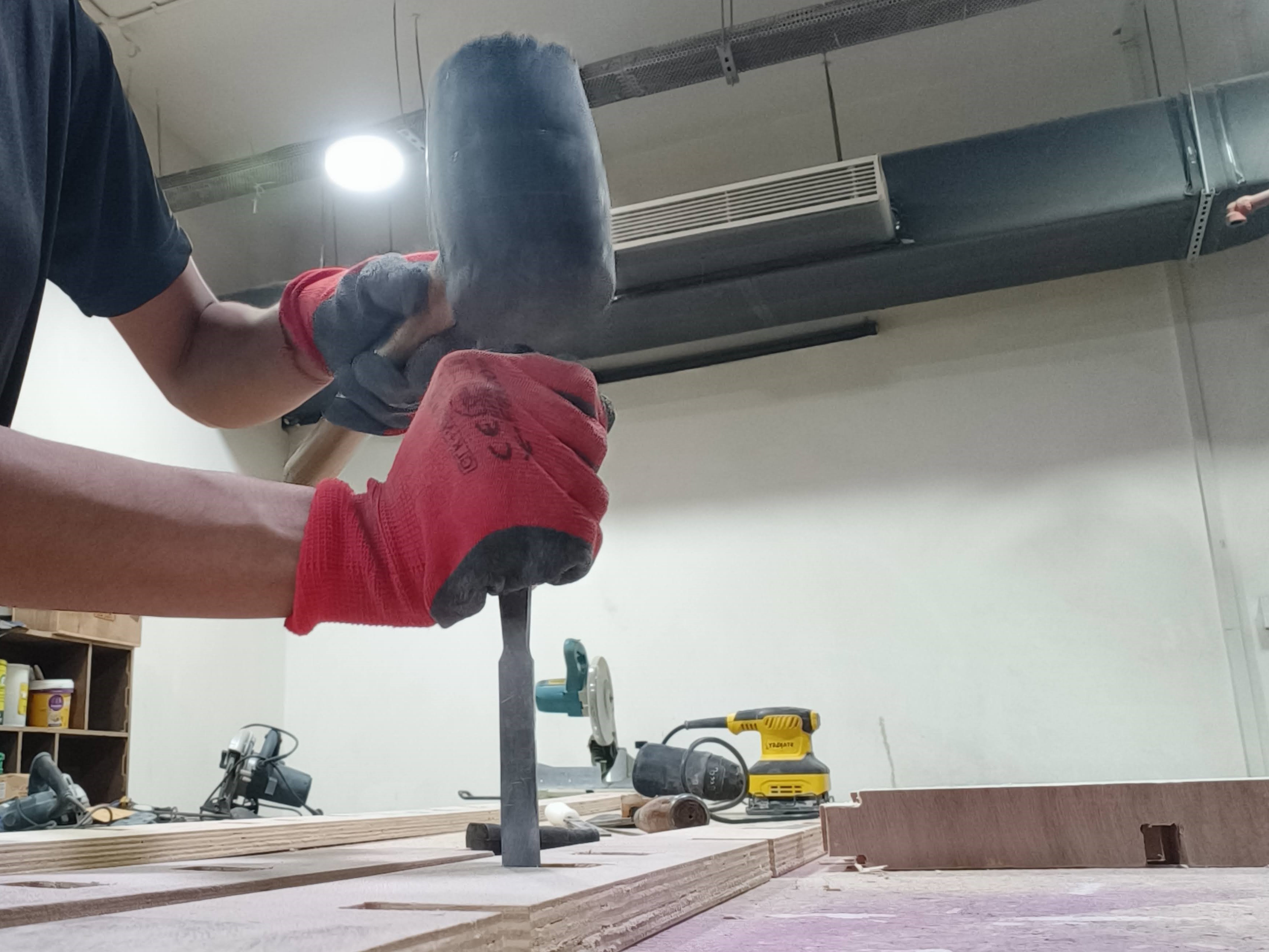 With the help of Saheen, i started the final assembly .We had to clamp together some parts to keep the legs in
place to hammer down the shelf pieces.
With the help of Saheen, i started the final assembly .We had to clamp together some parts to keep the legs in
place to hammer down the shelf pieces.
 While hammering down one of the legs, due to the poor quality of the ply , the end of the leg broke. :-| .
We kept the broken piece aside and continued the rest of the assembly. Some of the crossbars cracked while
hammering too , but the rest of the joints helped to keep it standing without issues.
After A LOT of hammering and making adjustments to the fit, the shelf was completely assembled.
While hammering down one of the legs, due to the poor quality of the ply , the end of the leg broke. :-| .
We kept the broken piece aside and continued the rest of the assembly. Some of the crossbars cracked while
hammering too , but the rest of the joints helped to keep it standing without issues.
After A LOT of hammering and making adjustments to the fit, the shelf was completely assembled.
 The broken piece of the leg had to be fixed with glue to the rest of the leg.But other than that the entire
shelf was stable and didn't require any additional fixtures.
I would like to clean up the holes of the slots as you the fit is not flush to the surface due to the
adjustments made
The broken piece of the leg had to be fixed with glue to the rest of the leg.But other than that the entire
shelf was stable and didn't require any additional fixtures.
I would like to clean up the holes of the slots as you the fit is not flush to the surface due to the
adjustments made
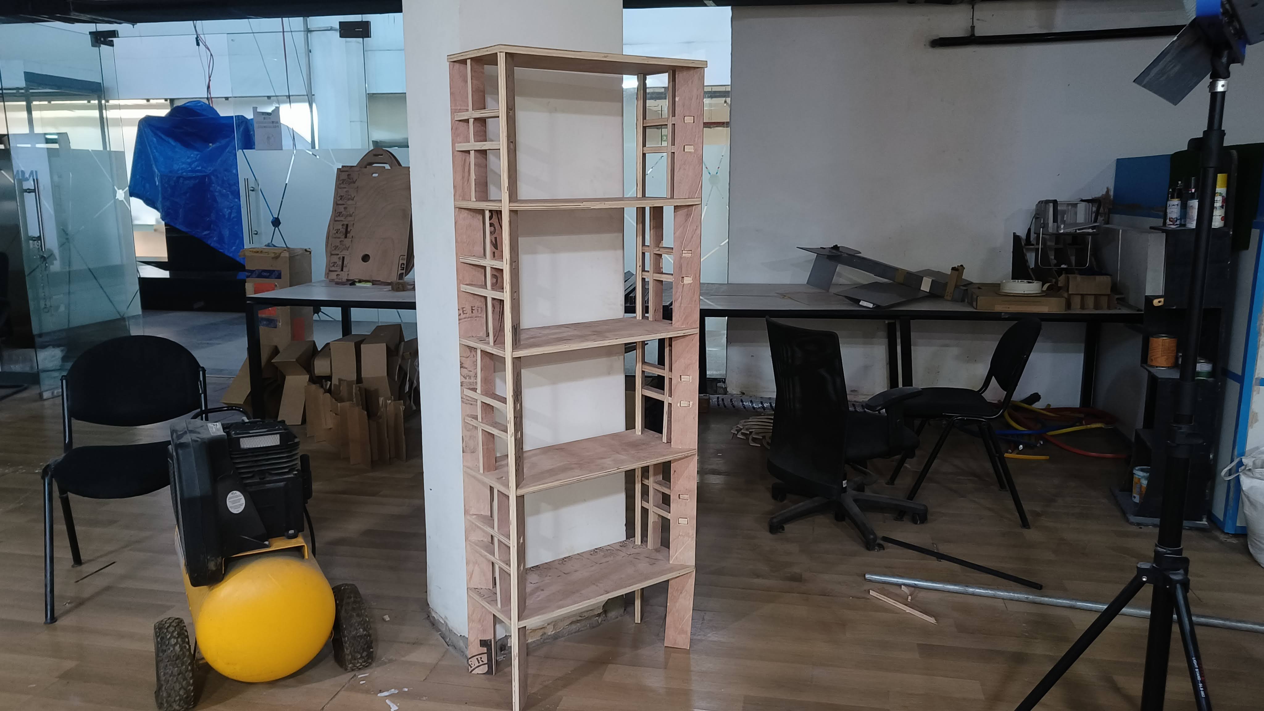
Finally the project was done and I'm happy that the shelf is standing with the design that i originally imagined
because halfway through
i honestly thought it wouldnt be possible to finish it.
Please be aware of the clearances and the capabilities of the machine while doing such assignments. ( ̄ヘ ̄;)
Download files
Shelf design dxf file
Vcarve file