This week I learned what embedded programming constitutes.
Group assignment: demonstrate and compare the toolchains and development workflows for available embedded
architectures
Individual assignment: browse through the data sheet for your microcontroller write a program for a
microcontroller, and simulate its operation,
to interact (with local input &/or output devices) and communicate (with remote wired or wireless connections)
extra credit: test it on a development board extra credit: try different languages &/or development
environments
rp2040-datasheet
This diagram shows the system overview of the RP2040 Microcontroller
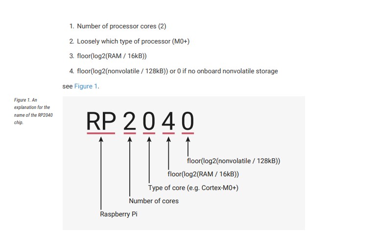
rp2040 datasheet
Some of the features of rp2040 include:
Dual Cortex M0+ processor cores, up to 133MHz
264kB of embedded SRAM in 6 banks
30 multifunction GPIO
6 dedicated IO for SPI Flash (supporting XIP)
Dedicated hardware for commonly used peripherals
Programmable IO for extended peripheral support
4 channel ADC with internal temperature sensor, 500ksps, 12-bit conversion
USB 1.1 Host/Device
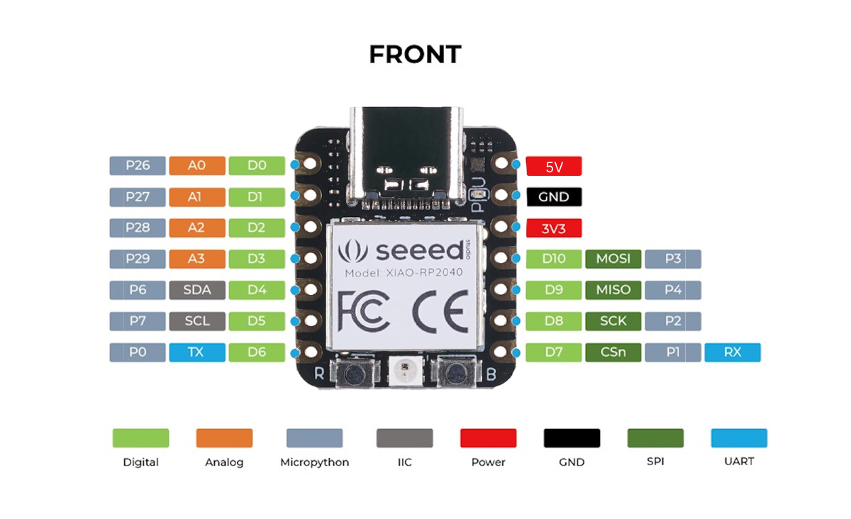
Pinout Diagram
A "pinout diagram" is a diagram or list that shows the arrangement and function of the pins (or terminals) on an
electronic component or connector,
helping users understand how to connect and interact with the device.
Shown below is the pinout diagram of a xiao rp2040 microcontroller.
XiaoRP2040-pinout
The various uses of the pins are explained in the datasheet as shown below:
XiaoRP2040-pin data
Each individual GPIO pin can be connected to an internal peripheral via the GPIO functions defined below. Some internal
peripheral connections appear in multiple places to allow some system level flexibility. SIO, PIO0 and PIO1 can connect
to all GPIO pins and are controlled by software (or software controlled state machines) so can be used to implement
many functions.
Understanding Arduino IDE and Micropython
Micropython
MicroPython is a lightweight version of Python designed for microcontrollers, while Arduino IDE is a
platform for writing and uploading code to Arduino boards, typically using C/C++.Allows for easy interaction with
hardware through GPIO pins,
sensors, and actuators.
Arduino IDE
It is a software environment for programming Arduino microcontroller boards.
Arduin IDE provides an easy-to-use interface for writing, compiling, and uploading code to the board.
It is widely used in hobbyist, DIY, and educational projects for electronics and robotics.
It includes very helpful libraries and built-in functions to get started with a program and simplifies hardware
interaction.
Programming
This week i tried to learn how to program a microcontroller using Arduino IDE (C/C++) and Thonny
(MicroPython).
To understand how to write the code we tried write simple code to function an LED.
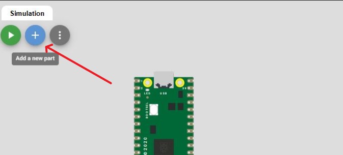
Trying out WOKWI
WOKWI is an online simulator for microcontrollers, allowing users to test and
debug embedded systems without needing physical hardware.
It supports various microcontrollers, including the Raspberry Pi Pico, Arduino boards, and ESP32,
along with virtual peripherals like LEDs, buttons, sensors, and serial monitors. i tried to simulate and learn
basic codes to work a circuit.
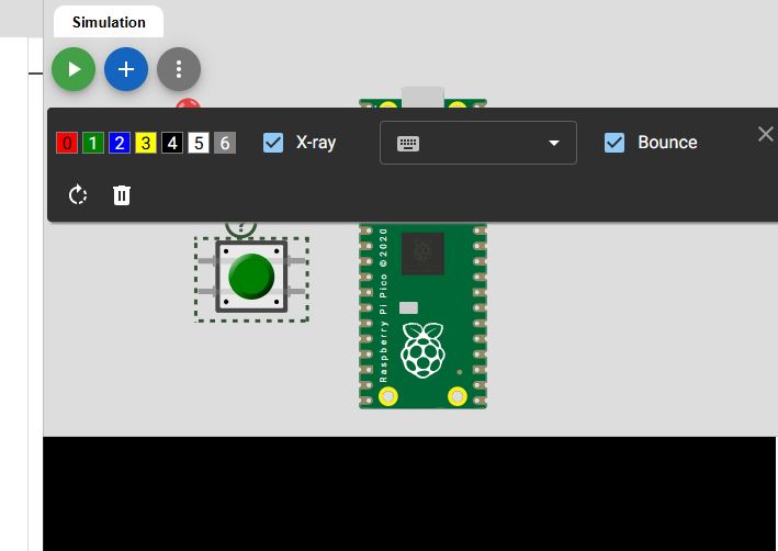
. Open Wokwi and make an account for yourself and add a new project
Select Pico as Microcontroller. Also select the language as Micropython.
Since this was the the first time i was doing
this i went with a simple circuit
containing a LED that will turn on with a push button switch.
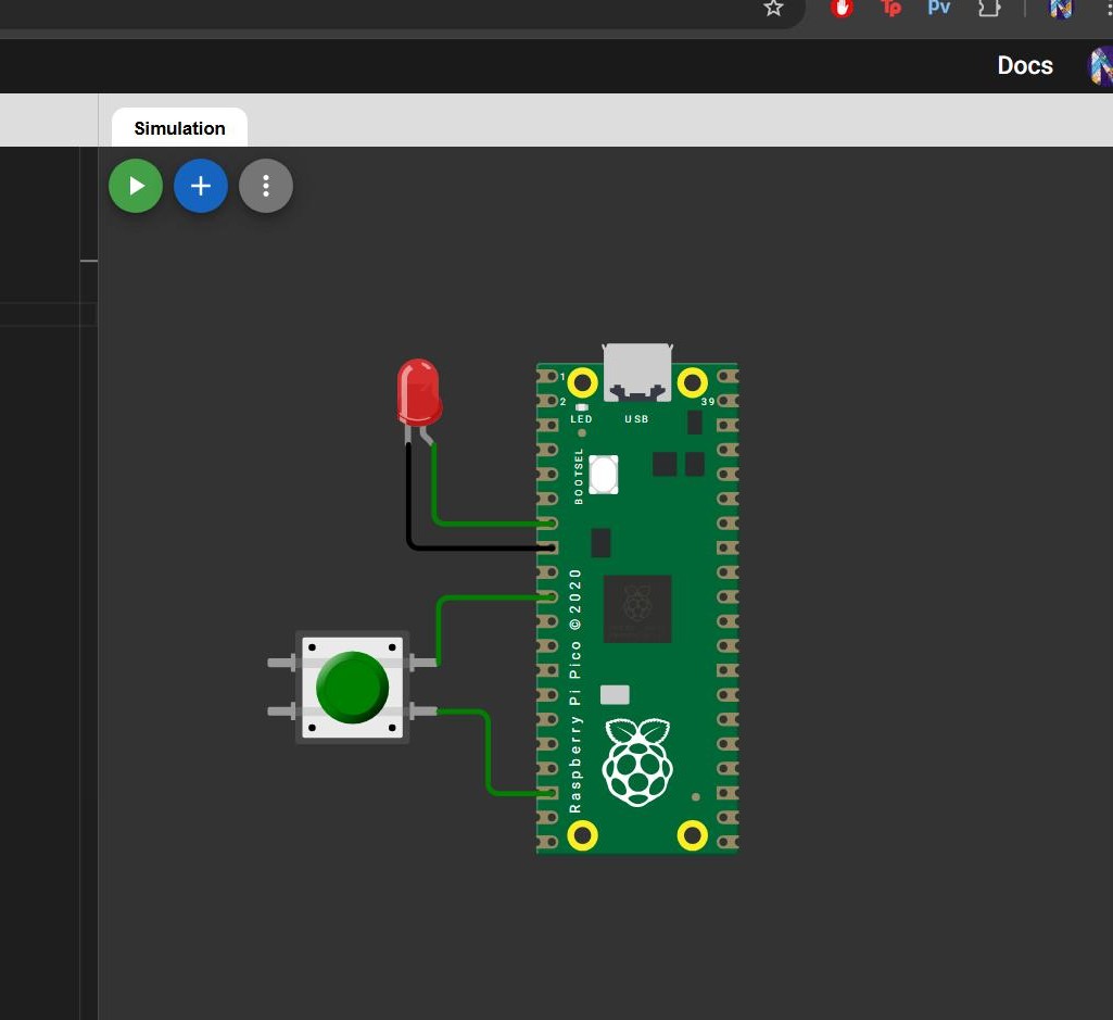
A templete with the raspberry pi board will appear on the screen along with a window on the left for writing
the code.
Now we can add components and write codes to simulate an action. Click on the '+' to add components.
We can change the parameters of the components according to what we need. just click on the component and a
toolbar pops up where you can set the parameters.
So i placed an LED on to the board and connected its ends to a ground pin and another available pin.
Similarly add a push button switch to the circuit
Now that the components are set up we need to write the code to make it work the way we need it to.
I tried to write the code using micropython.
First we need to import the required libraries into the code using the import command. in this circuit we we
need to
import pin and time.The Pin
function lets us use the GPIO pins from our microcontroller.The sleep function is imported to add a delay to the
program.
   from machine import Pin
   from utime import sleep
Now we have to set up the pins and name the variable. Here we need to define that the Led is an Output.We also
define the button as an input.
    from machine import Pin
    from utime import sleep

    led = Pin(1, Pin.OUT)
    button = Pin(7,Pin.IN,Pin.PULL_UP)
Next we can apply funtions to the code .
To make the led turn on when the button is pressed the following code is written .
  from machine import Pin
  from utime import sleep

  print("Hello, Pi Pico!")

  led = Pin(1, Pin.OUT)

  button = Pin(7,Pin.IN,Pin.PULL_UP)

  while True:

      if button.value() == 0:
          print("Button pressed, LED on")
          led.value (1)


      else :
          led.value(0)
The while loop executes a set of statements as long as a condition is true. The if statement executes a code
based on whether a certain condition is true or false. The else statement is an alternative code block to execute
if the if condition is false.
I also tried adding another blue led and made them turn on/off using the button in various ways. The simulation below shows when the blue led turned on initially and when the button is switched on the red led turns on and the blue led turns off.
    from machine import Pin
    from utime import sleep

    print("Hello, Pi Pico!")

    led = Pin(5, Pin.OUT)
    led2 = Pin(2,Pin.OUT)
    button = Pin(7,Pin.IN,Pin.PULL_UP)

    while True:

        if button.value() == 0:
            print("Button pressed, LED on")
            led.value (1)
            led2.value(0)

        else :
            led.value(0)
            led2.value(1)
Switching on an LED using serial communication
As per some feedback from Pablo I worked on lighting up an LED using Serial port communication
I referred to this document to get the code and made some changes to the syntax to make it work in Wokwi.
When 'H' is entered in the serial port the led turns on and when 'L' is entered the LED turns off.
#Switching on an LED using serial communication
#define ledPIN 13
char incomingChar; // for incoming serial data

void setup() {
  Serial1.begin(115200); // opens serial port, sets data rate to 115200 bps
  pinMode(ledPIN, OUTPUT);
}

void loop() {
  // send data only when you receive data:
  if (Serial1.available() > 0) {
    // read the incoming byte:
    incomingChar = Serial1.read();
    if(incomingChar == 'H')
    {
      digitalWrite(ledPIN, HIGH);
      Serial1.println("LED is ON");
    }
        if(incomingChar == 'L')
    {
      digitalWrite(ledPIN, LOW);
      Serial1.println("LED is OFF");
    }

  }
}
Using Arduino IDE
I had to install Arduino IDE first as this was my first time
using it.
I felt like the interface of this software was quite easy to follow and there was a lot of refrence libraries
and example codes to use and follow.
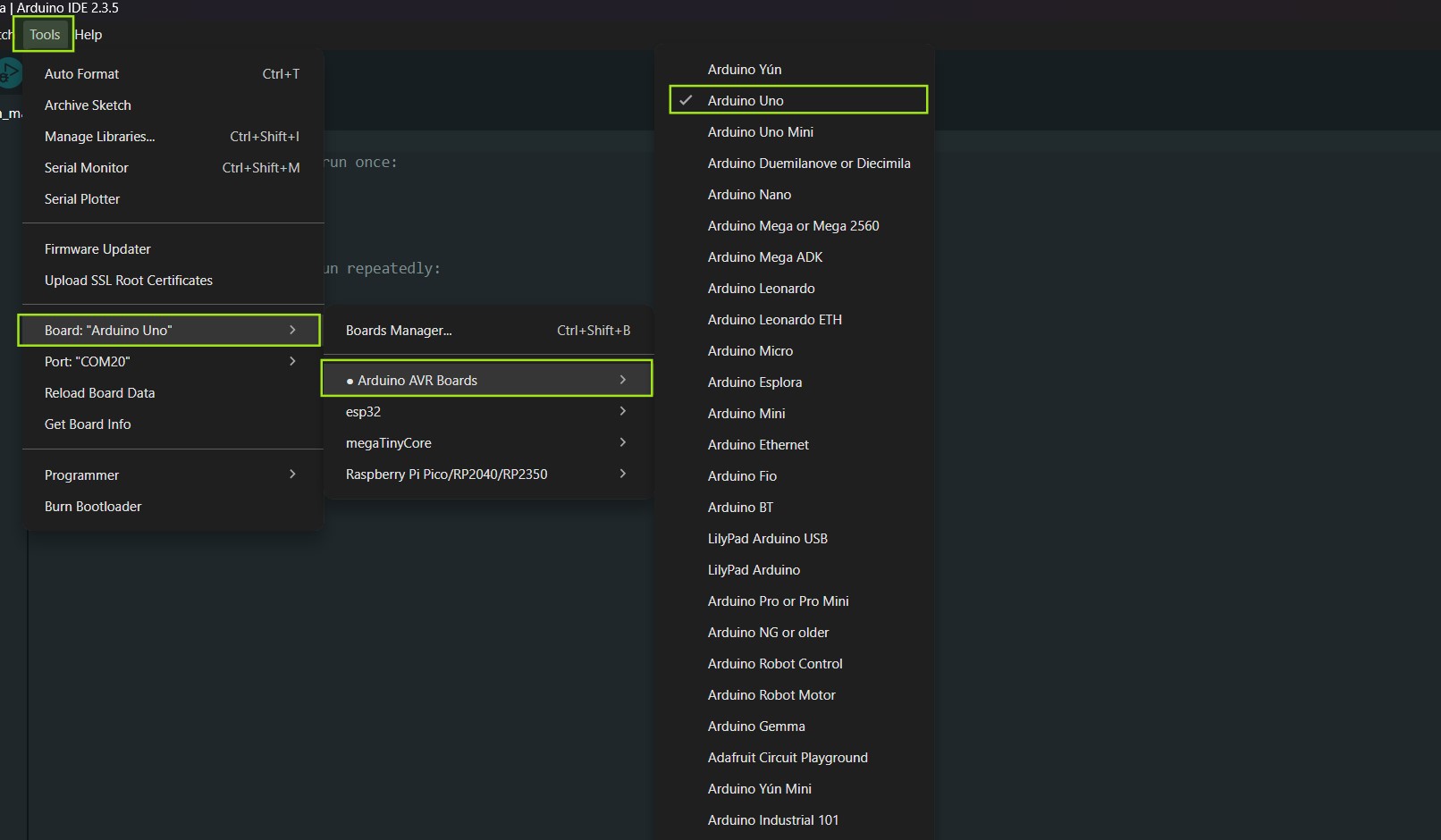
We need to setup the New sketch according to the board that needs to be programmed. Go to tools >> select board
>> choose the board you will be programming (in this case Arduino Uno).
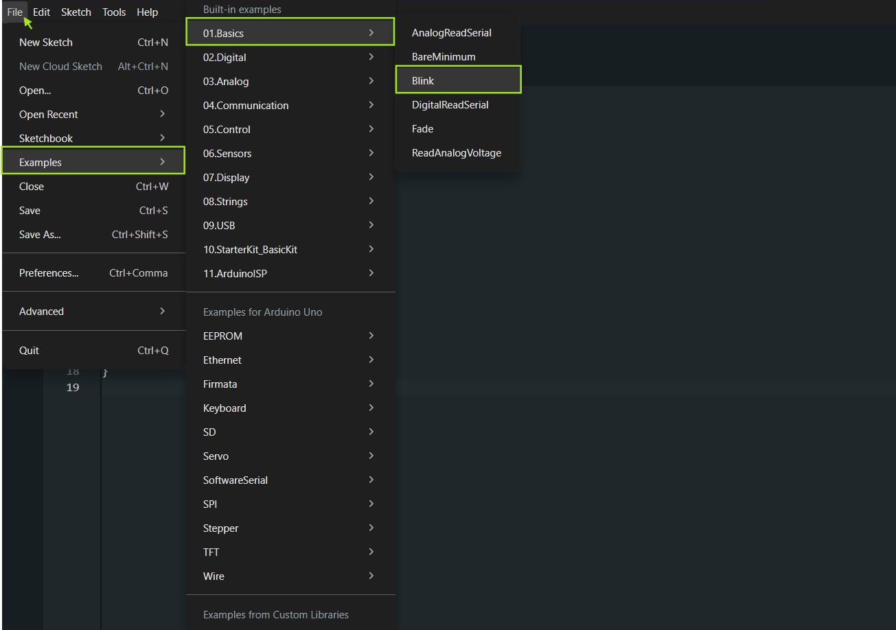
I used an Arduino Uno board and attached a power led to it used a example code to blink the LED.To get the
example code first go to file >> Examples >> Blink
Next choose the port to which the board is connected.
I tried out some sample codes.
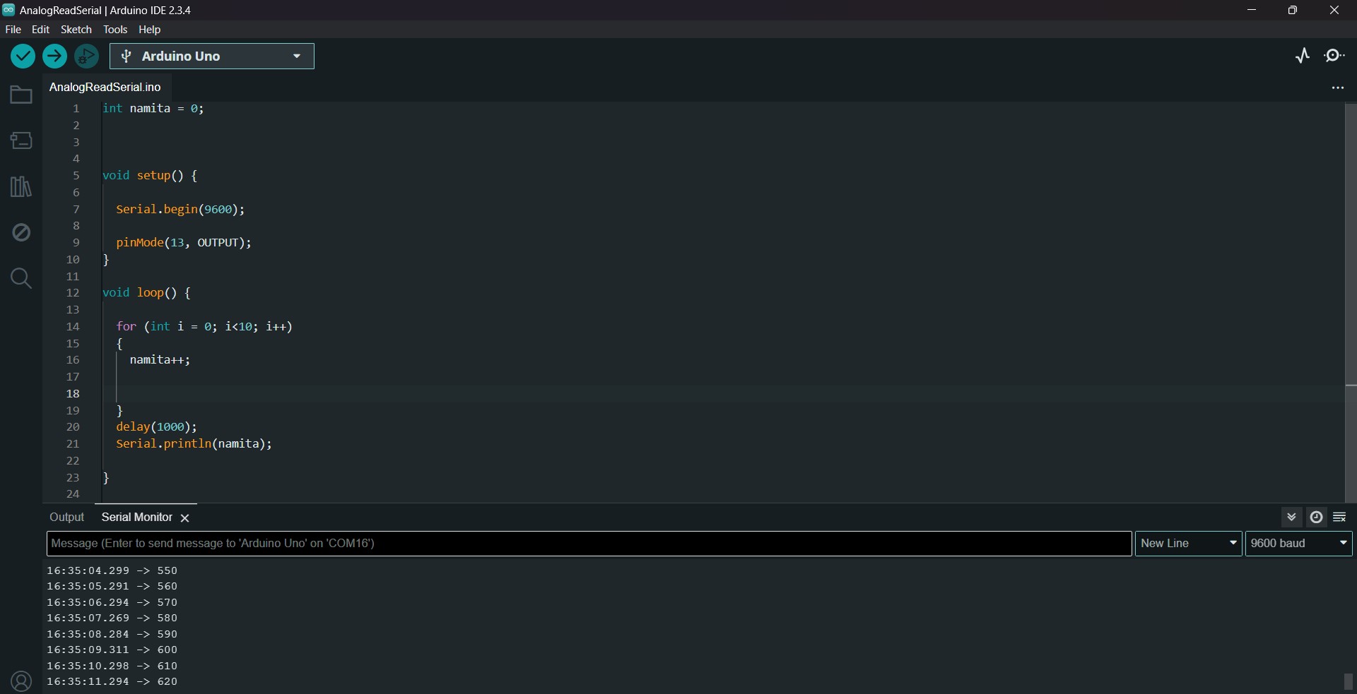
Then just as an exercise i made a code to blink the led when an initialised variable(in this case the variable is 'namita') which is incrementing becomes a multiple of 5
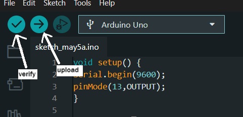
You can compile the sketch to check for any errors made while writing code (such as missing a library or
missing out on putting the';" after a declaration ).Then we can upload the code to the board.
We can see the output on the serial monitor so that we can observe how the board responds to the code.
The led was blinking whenever a multiple of 5 was encountered while counting.