model (raster, vector, 2D, 3D, render, animate, simulate, ...) a possible final project,
compress your images and videos,
and post a description with your design files on your class page
2D design
Raster and Vector Graphics
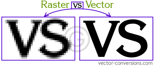
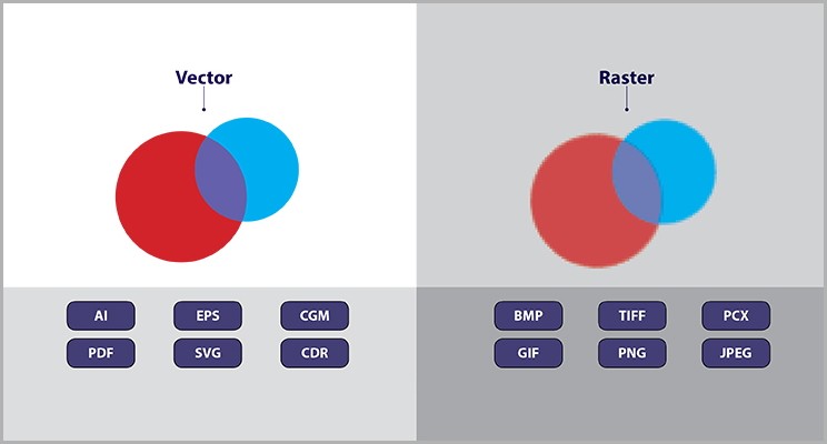
Raster and vector are two types of image formats used in digital graphics.
Raster Images
Raster images are made up of a grid of individual pixels, each with its own color and value.
Common formats include JPEG, PNG, and GIF. Digital photographs, screenshots, and images you see on the web are
typically raster images.
s.
However, they lose quality when scaled up, as pixelation occurs.They are typically edited in software like Adobe
Photoshop or GIMP.
Vector Graphics
Vector images are created using mathematical equations to define lines, curves, and shapes. They can be resized
infinitely
without any loss of quality, as the computer can recalculate
the image based on the mathematical equations, making them ideal for logos, illustrations, and diagrams. Vector
images are typically edited in software like Adobe Illustrator, CorelDRAW, or Inkscape.
Popular vector formats include SVG, EPS, and PDF.
Exploring Vector Tools
Adobe
Illustrator
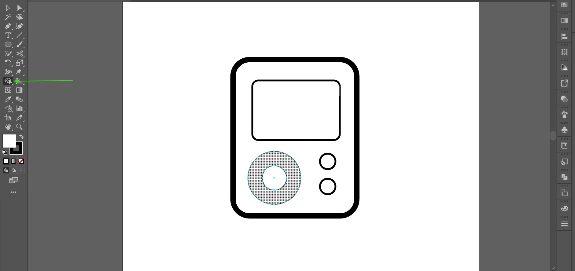
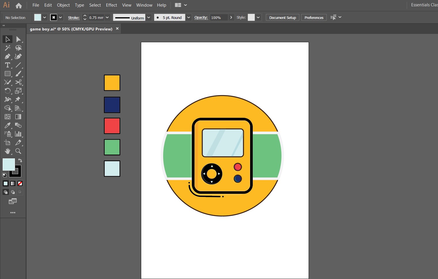
I usually use illustrator as my go to software for creating vector graphics. For this week i tried to make a
gameboy inspired simple icon using illustrator tools.
We open a new document to start our work. I wanted to use simple shapes to create an effective graphic. To make
the body i used the rounded rectangle tool. i made a smaller rectangle to make the screen. The fillet can be
manipulated by pulling the small dot that you see wen the shape is selected.
Then i made customized buttons. I used the circle tool to make the 2 simple buttons. Then i made 2 concentric
circles for the scrollpad. To furthur clean up the shape i used the
shape builder tool to remove the parts i did not require.
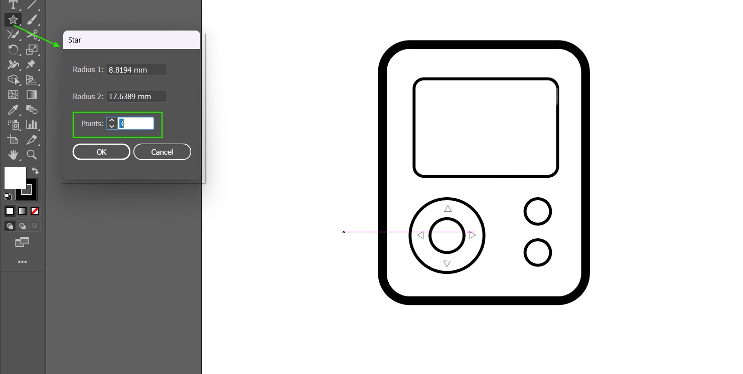
I made the arrow keys by making a triangle using the star tool. Click on the tool and a dialogue box opens which
lets you choose the number of points of the star. Type in 3 for a triangle. You can either copy and paste, then
rotate for the rest of the triangles or right click on the shape > go to transform> reflect (select copy to create
copies).
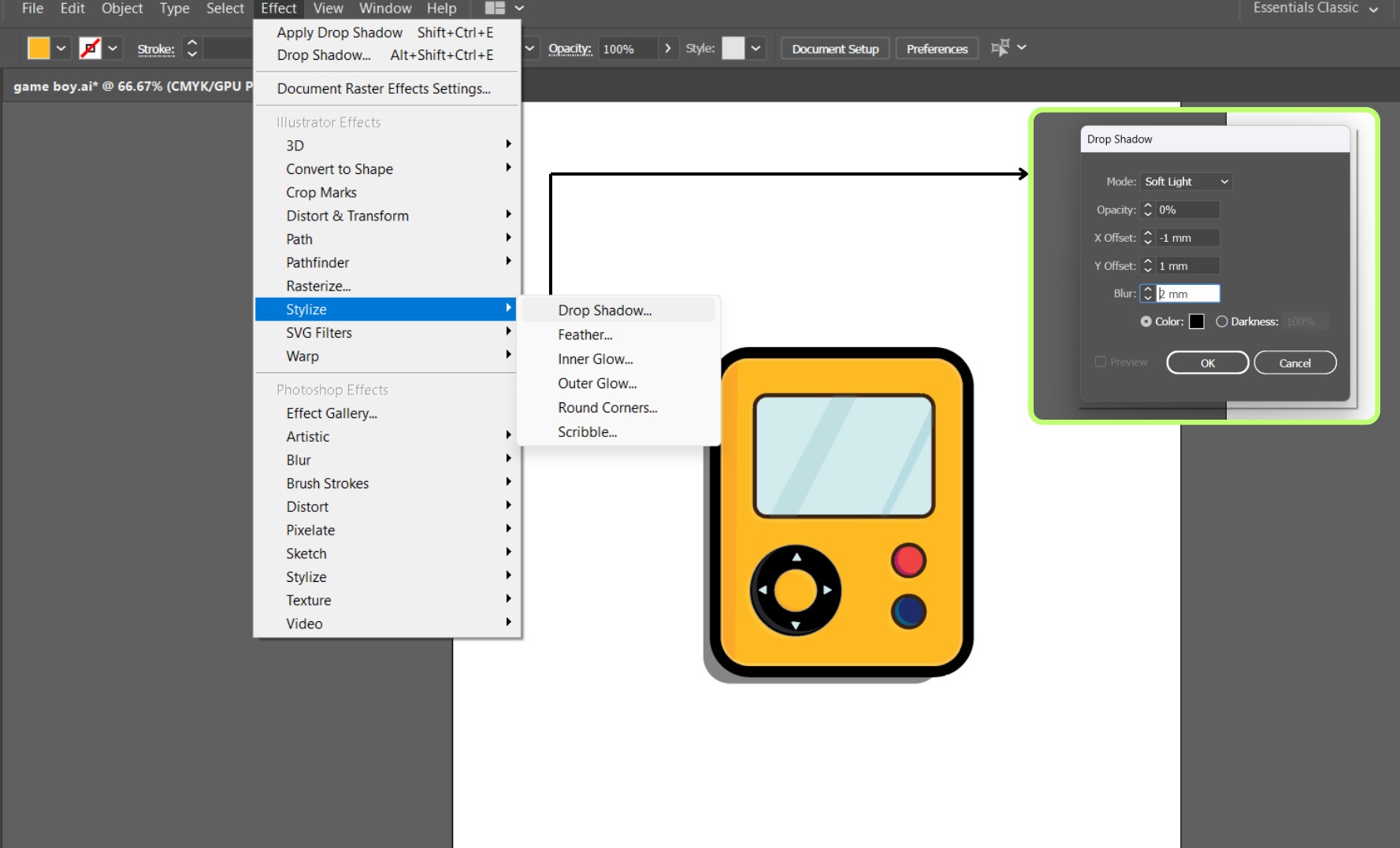
next i filled in the colours and made it vibrant and pop out by changing the fill colour. I also increased the
the stroke width to give it the feel of an icon. I wanted to add some shadow to the buttons and the body. For this
we can use the drop shadow option as shown:
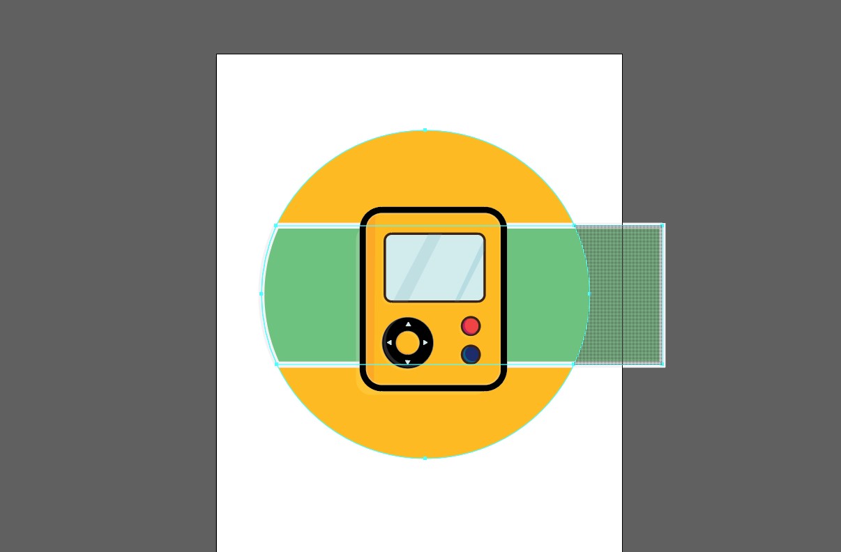
Then i made a background for the icon using a circle and rectangle, and using shape bulider again to remove
certain parts.
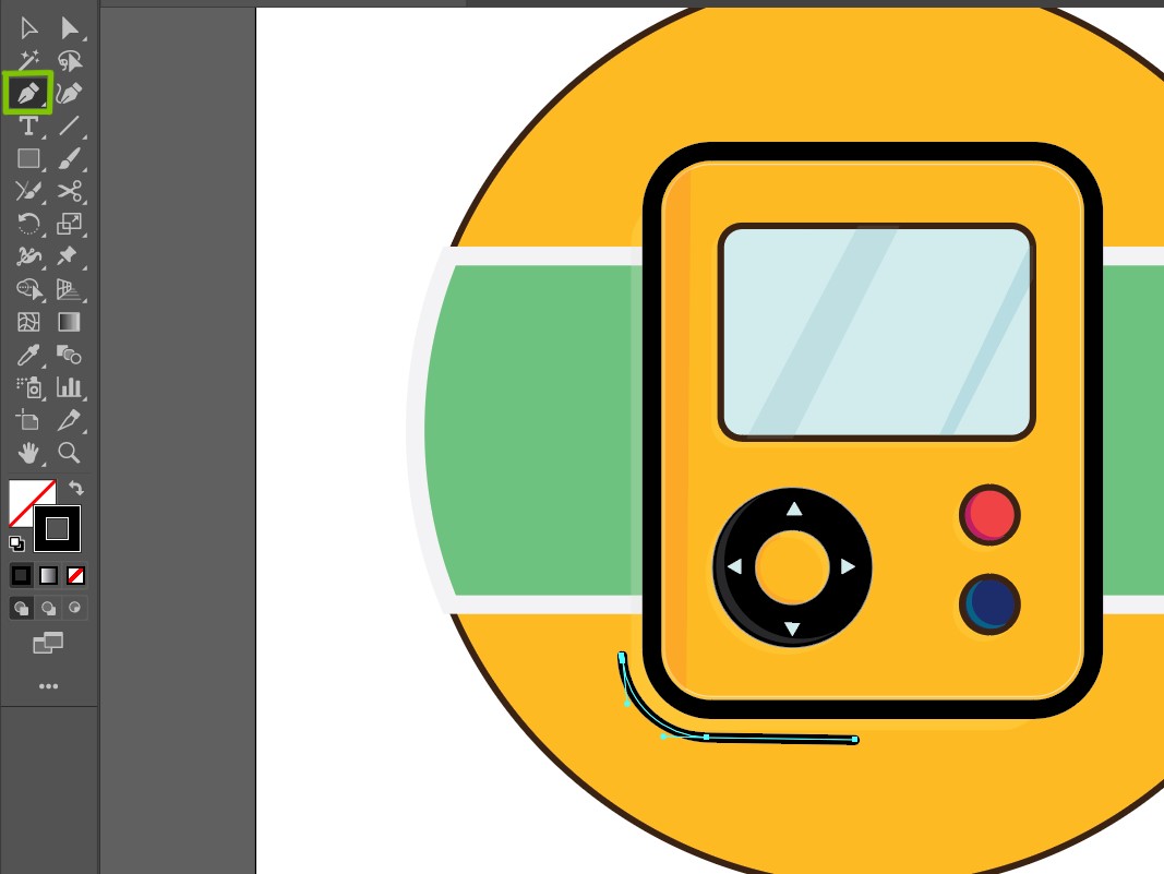
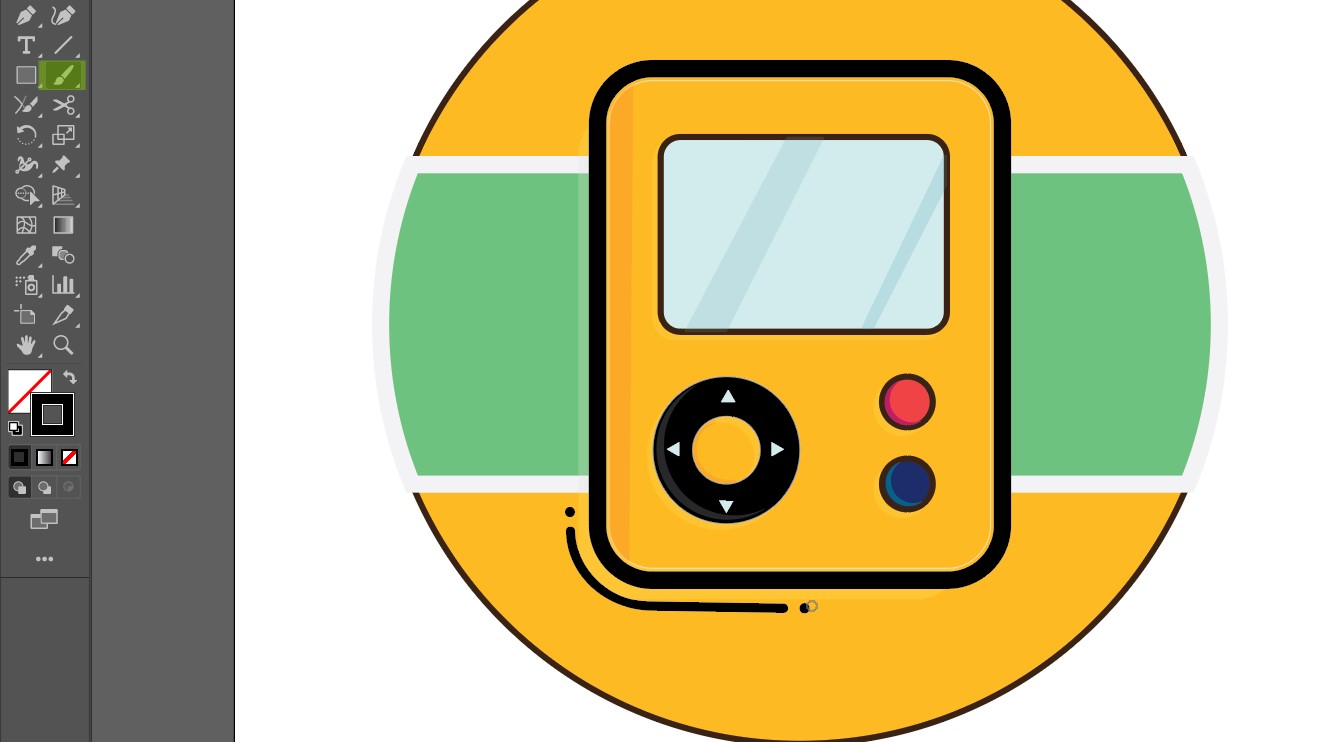
Using the pen tool i made some lines just to emphasise the design. I also used the brush tool just to add a dot
instead of using a circle.
This was the final look.
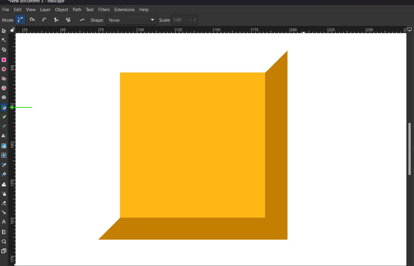
Inkscape
Inkscape is a vector graphics editor. It is used for both artistic and technical illustrations such as cartoons,
clip art, logos, typography, diagrams, and flowcharts.
I am not that familiar with inkscape so it took a bit of time to undertsand where each tool was located and how
it functioned.
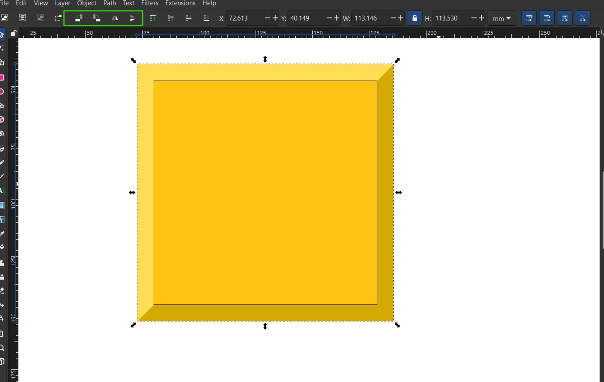
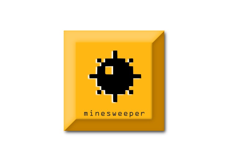
So i started of making some simple shapes and played around with the pen tool too. I decided to make a logo for
the minesweeper game.
I made the basic outline and filled in the colours in such a way that emulated a shadow and made the surface
look projected.
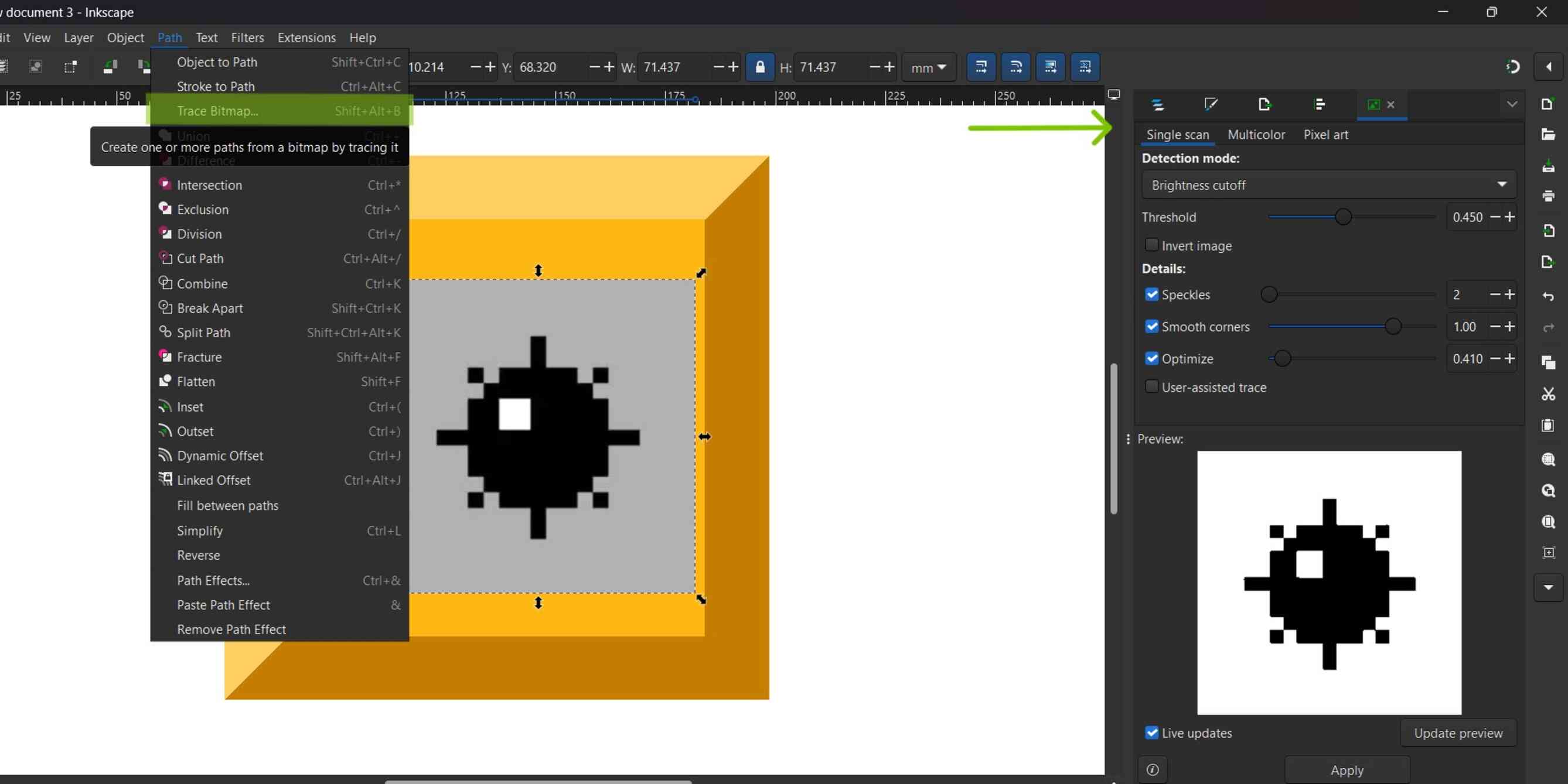
Then i went on to search up the logo of a minesweeper mine and imported it into the canvas.
I used the trace bitmap function to make a silhoutte of the image.I then placed it on the center of the yellow
rectangle.
I also used the text box tool to write some text to finish off the logo.
I also made more tiles that look like the minesweeper tiles with the numbers in them.
Exploring Raster tools
Photopea
I usually use photoshop to edit and manipulate picture.
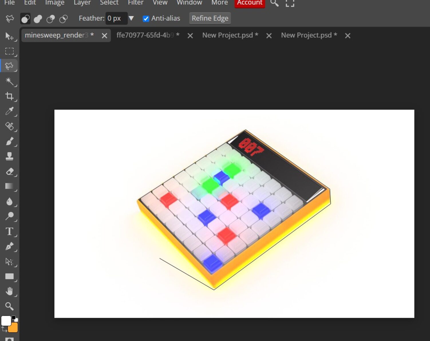
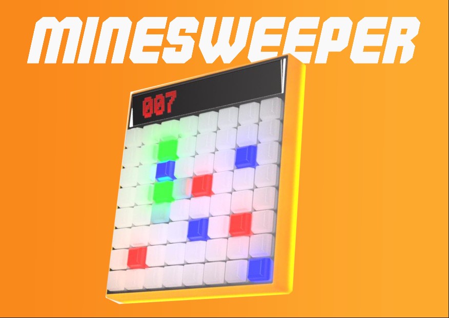
This time i wanted to use Photopea to make a product poster of my project. I used the 3D render i made using
Fusion360 for this.
Photopea is a web-based photo and graphics editor .compatible with raster and vector graphics, such as
Photoshop's PSD as well as JPEG, PNG, DNG, GIF, SVG, PDF and other image file formats.
The software supports layers, layer masks, channels, selections, paths, smart objects, layer styles, text layers,
filters and vector shapes.
Open Photopea on your browser and start a new project.
Then i opened the render image . I had made the render of the product in a white background (I chose an image
with a background instead of a transparent background to explore the tools in photopea)which i would like to
remove.
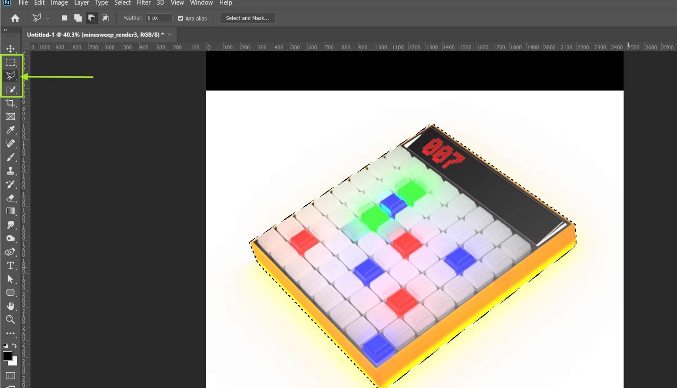
To do this I used the lasso tool to select the edges of the casing. The automatic selection tools did not give a
clean selection so i had to manually make the selection using the Polygonal Lasso tool under the lasso tool option
in the sidebar.
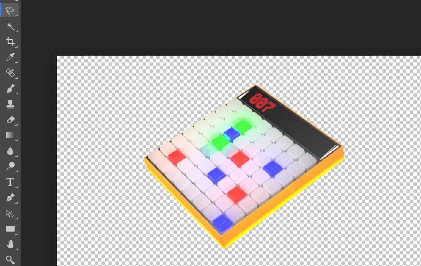
Then i deleted the unselected portion. You can also copy and paste the selection if you would like to preserve
the original image.
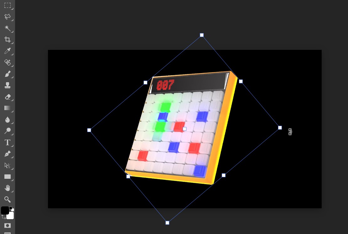
Next i wanted to change the orientation of the image. Click on the image and the transform controls will show up
with which you can scale the object or rotate it using the vertice control points.
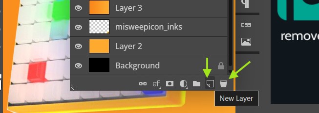
I created a new layer for the background. You can add or delete layers in the layers pane.
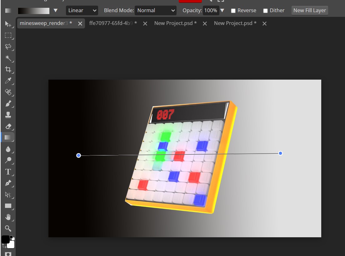
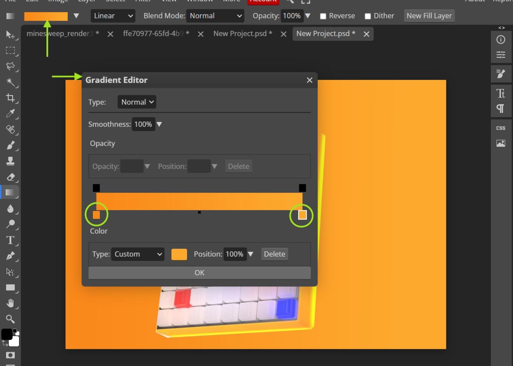
I thought of making background colour to be a monochromatic gradient. For this i made use of the gradient tool.
Drag a line across the layer to positon the gradient.
We can change the colours of the gradient in the gradient tool settings. You can click the colour bar on the
ribbon , which will open a dialogue box where you can change, add and control the opacity of the colours.
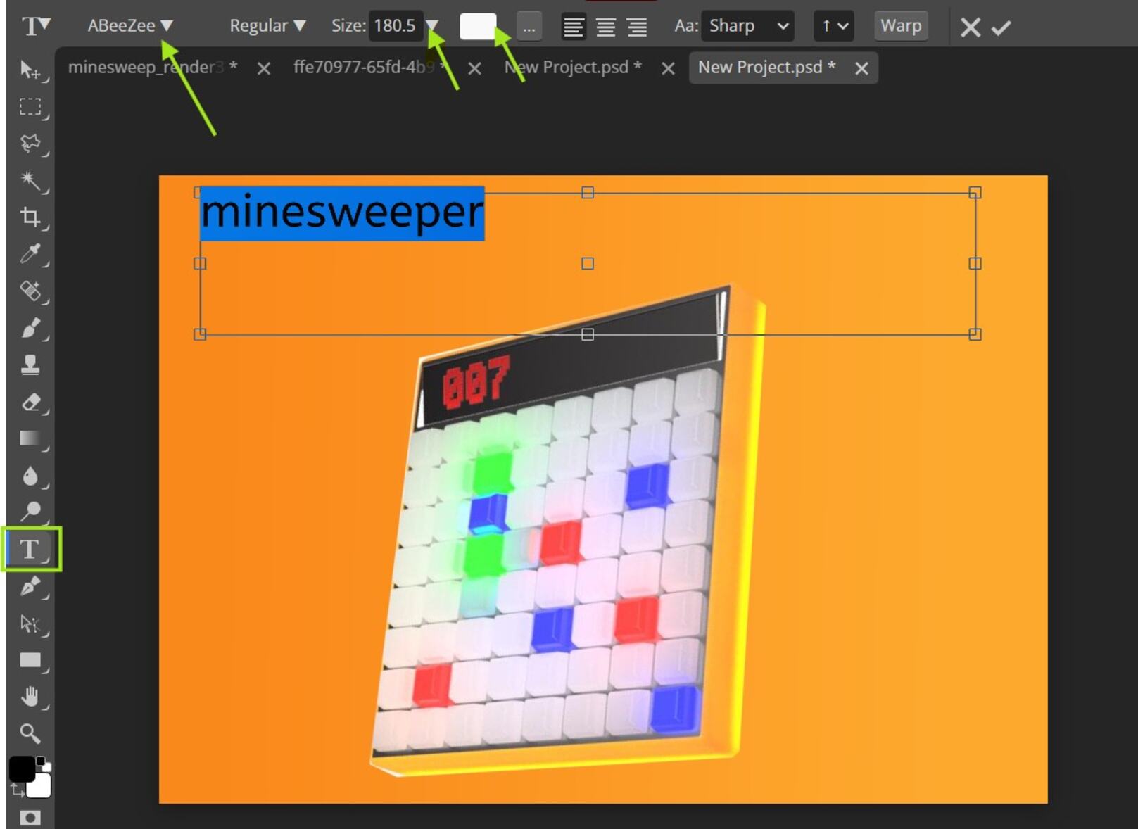
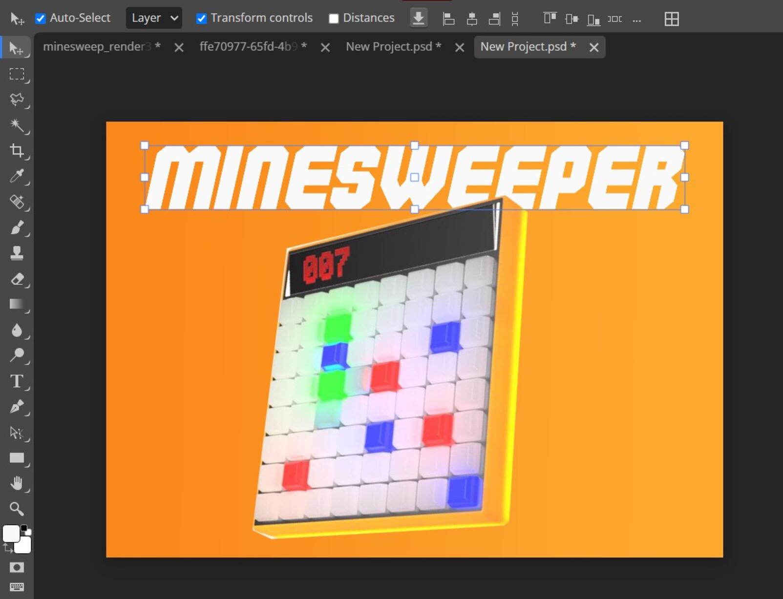
Now i needed to add a typography to the poster. To add text , Click on the 'T' icon(Shortcut : Press "T").
You can change the font styles,sizes,colours,alignments etc according to your design. The text used here is
called commando
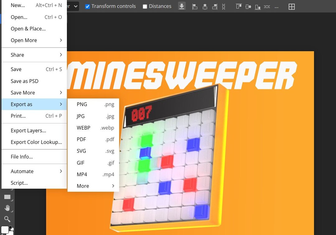
Once you are done with the design you can export to any of the file formats as required. It is also possible to
save the file as a .psd file.
Exploring 3D softwares
Fusion360
Fusion has built-in capabilities for 3D modeling, collaboration, simulation and documentation. It can manage manufacturing processes such as machining, milling, turning and additive manufacturing. It also has Electronic design automation (EDA) features, such as schematic design,
PCB design and component management. It can be also used for rendering, animation, generative design and may more.
I am quite new to Fusion360 so i wanted to to play around with the tools and also thought of making an concept model
of my final project
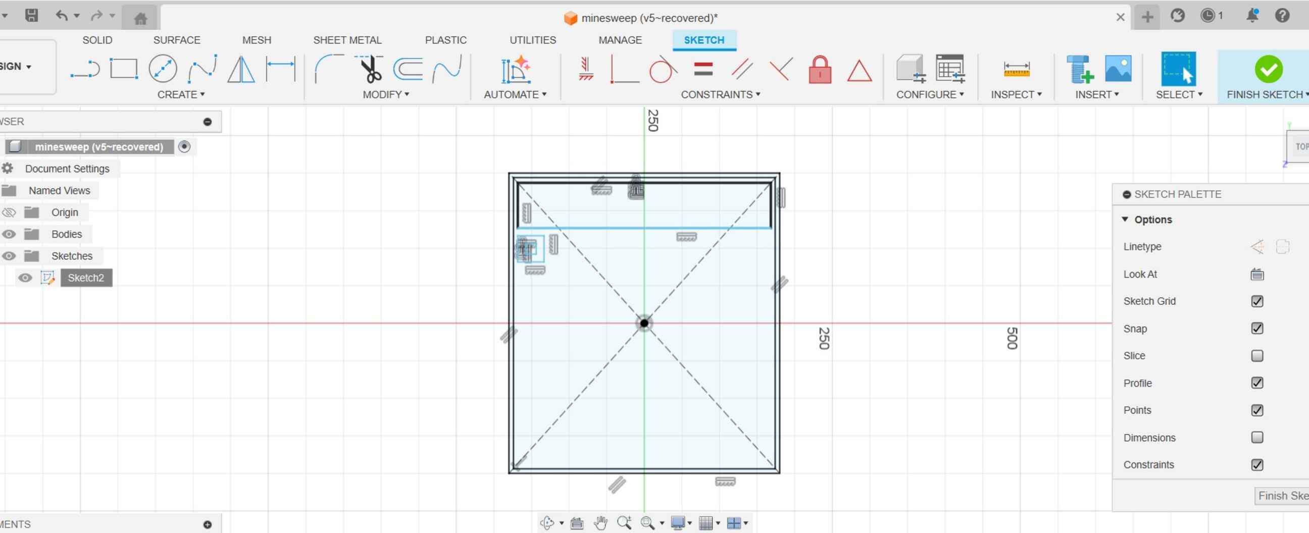
First we need to create a 2D sketch of the components. To do so select sketch , then choose the plane in which
you have to draw the sketch. That will take you to the skecth view.
I contructed the top view of the machine using multible sized rectangles
Once the sketch is done click on 'Finish Sketch' wihich will take you out of the skecth view. You can make edits
to the sketch later on too. For this right click on the the skecth you would like to edit from the browser tab and
right click >> edit sketch.
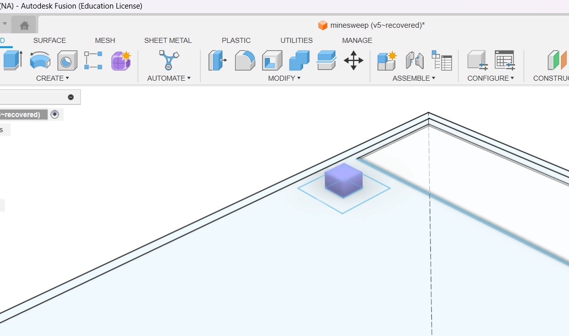
Next we can start creating surfaces for the body . For this i used the extrude tool . Click on the sketch areas
you would like to extrude.
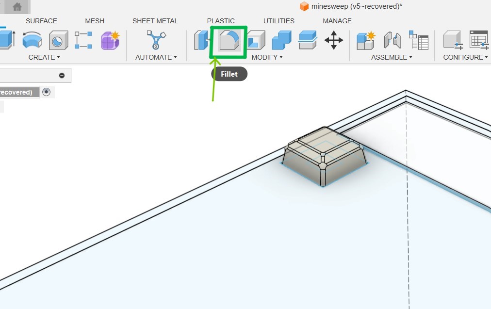
I had to make a body for the LEDs and a button.
I then added fillets to the button using the fillet tool from the toolbar.
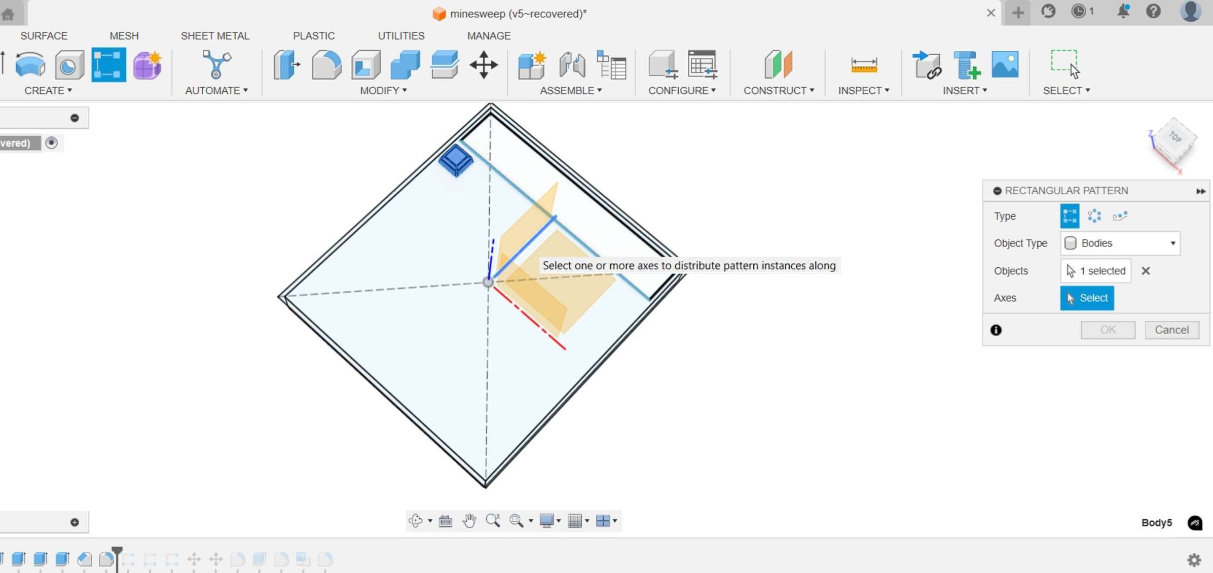
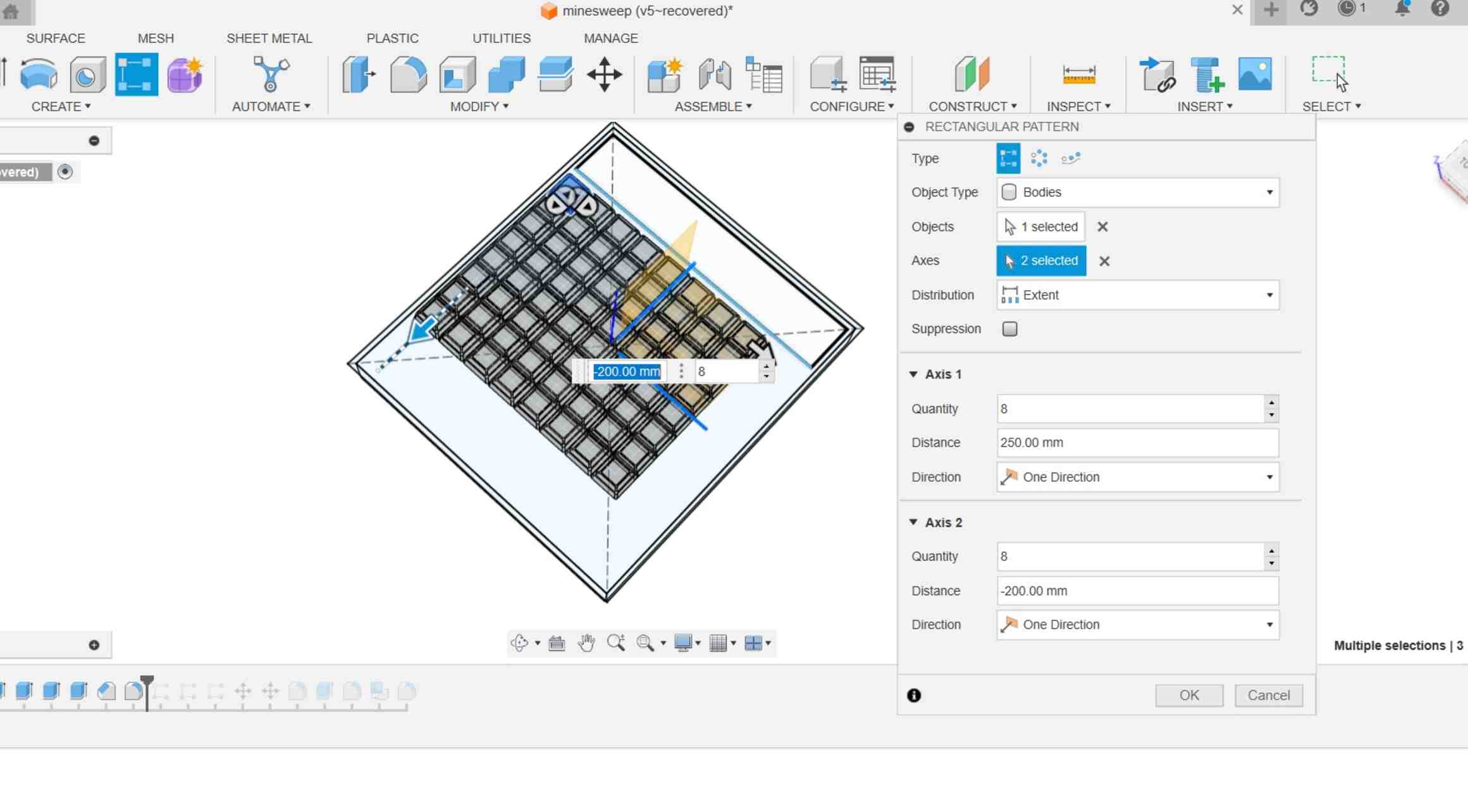
Next i needed to create multiple copies of the the led and the button. To do this kind of replication easily we
can utilise the array tools. Since i need a linear array i chose the rectangular array option.
A dialogue box opens up, where you can set up the axes in which you want the array to be made as well as the
number of items in each axis.
click ok and an array of parts is done.
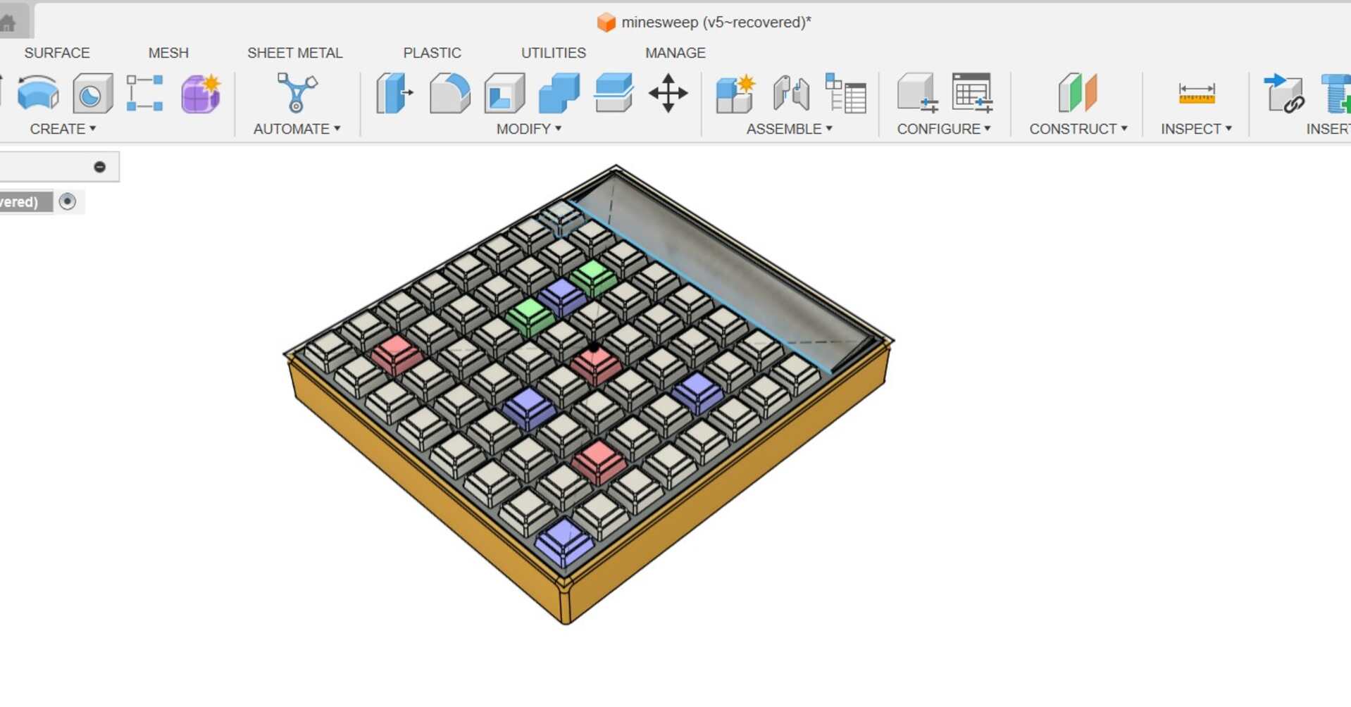
After that i extruded parts for the casing of the body and the display
We can choose different materials for different parts by opening the appearance tab(click 'A'). I set different
colours for the LEDs and adjusted the settings.
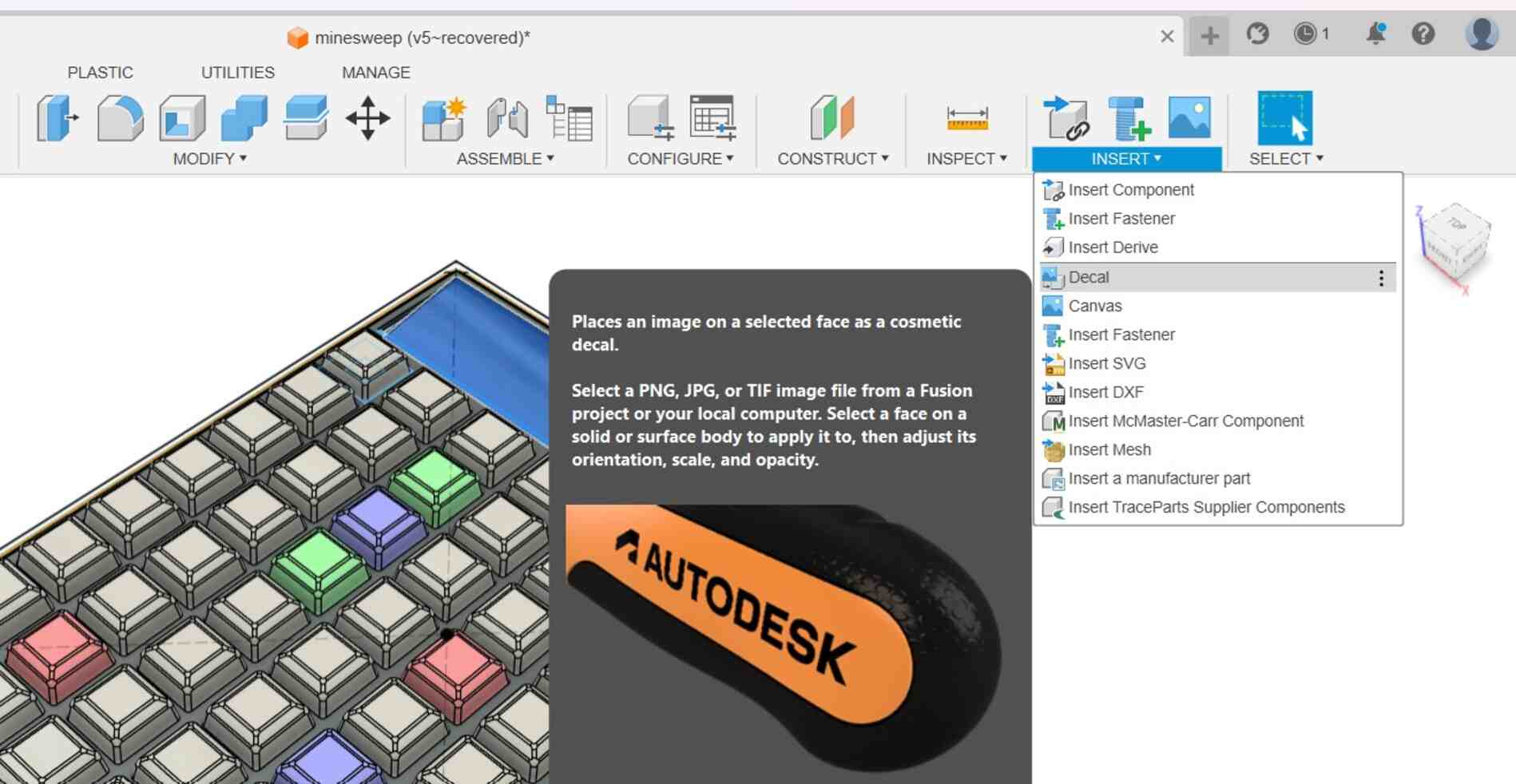
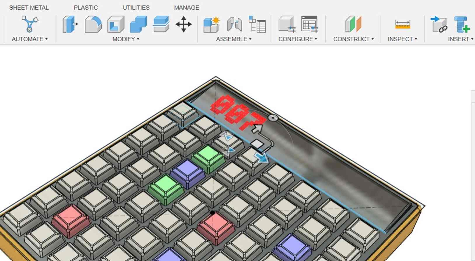
I wanted to add a graphic of the score on the diplay surface. For this i used the decal tool. The decal tool is
used to add graphics (such as branding or logos) on top of modelled surfaces. i had made a text graphic of the the
score on inkscape. Go to setup and Click on decal. Click on the picture icon and select the image.
Place and position the graphic according to your requirement.
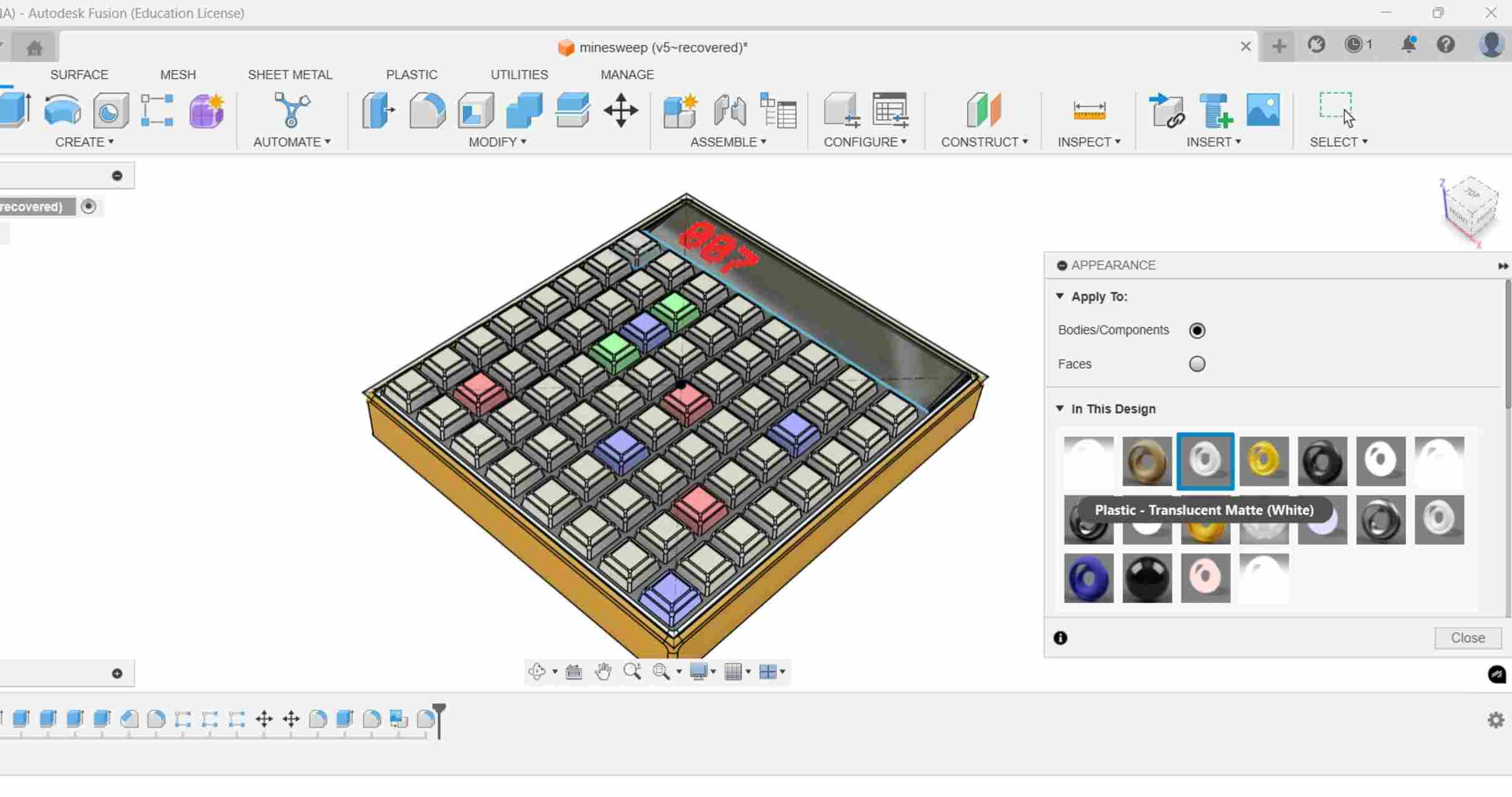
Next we can move on to render and add materials to the surfaces, For that you can go to the appearances tab
(click 'A') and play around with the material library according to your liking.
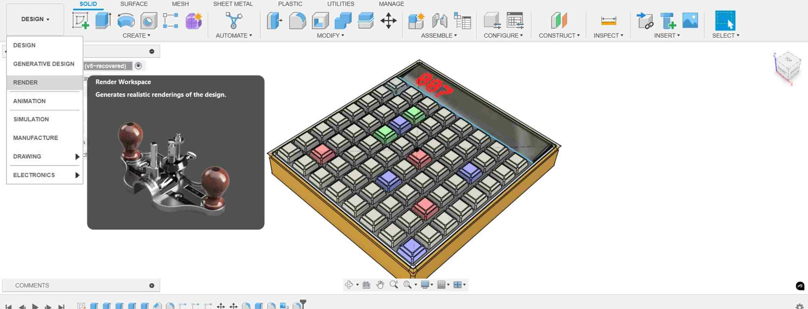
To see the render view go to the the design dropdown and click on Render. By clicking the setup tab ,which takes
you to a dialogue box,you can change the backgrounds and lighting of the view
Finally to get a high quality render click on the start render option to begin raytracing.
Rhino3D
Rhinoceros is used for computer-aided design (CAD), computer-aided manufacturing (CAM) see, rapid prototyping, 3D
printing and reverse engineering in industries including architecture, industrial design , product design as well as
for multimedia and graphic design.
Open rhino. There are 4 viewports that open up. Rhino3D's interface consists of multiple viewports (Perspective,
Top, Front, Right), each displaying the same 3D model from different angles.if you double click a viewport it will
turn into a maximised view of it. Changes made in any of the views will reflect on the other views as well. You
can work in layers in rhino,which can be customised according to the user .
You can use the right mouse button for panning and 3D navigation, scroll wheel to zoom, and keyboard shortcuts
to operate rhino.
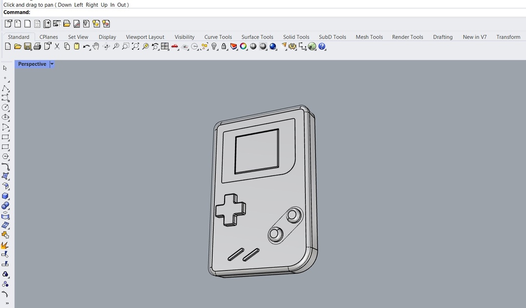
I thought of making the game console logo i made using illustrator to a 3D model to to explore different tools
basic commands in Rhino.
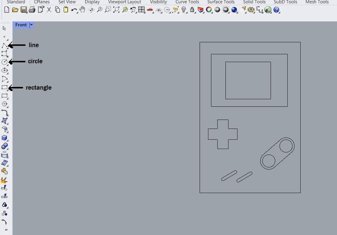
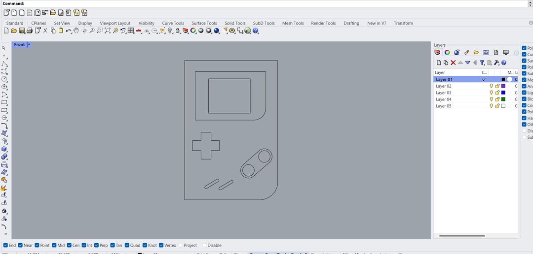
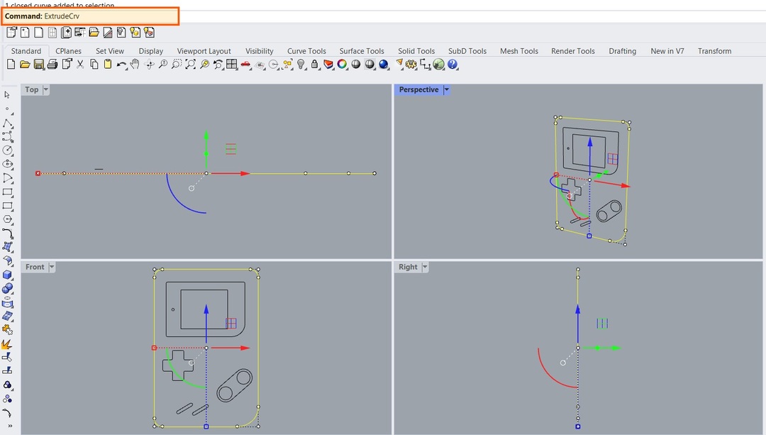
First we can make a basic 2D sketch of the console in the front viewport using the rectangle, line and circle
commands.Starting with the top view, using the rectangle tool i created the outer body and the screen.
Next I added some circles for the buttons and a rounded rectangle for their outline box. Then using the gumball
controls u can rotate the shapes to sit at an angle.
To access the tools you can either find them on the sidebars or you can type out the command to get them easily.
I added a fillet to the edges using the fillet tool. (Type 'fillet') . In the command bar , it will ask you to set
a fillet and other options to change the fillets. Click on the curves you want the fillet to be on and then Press
enter.
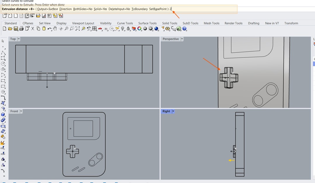
Once the basic outline is done we can extrude the objects using the "extrudeCrv" command and enter. It gets
easier when you learn the command prompts because you can easily acess the tools.Choose the curve you want to
extrude. and type the commad.You can either specify a distance or pick two points to define the direction and
distance.
You can create a solid or a face according to your requirement.
i used this command for differnt shapes according to the distance i wanted for each one.
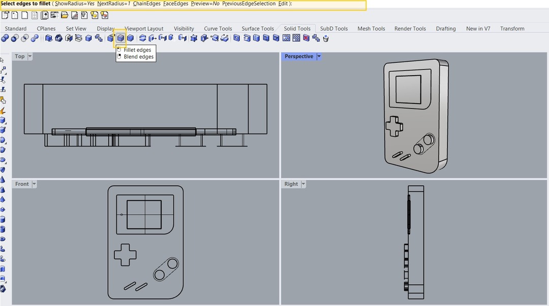
Next i wanted to add some fillets to the edges of the solid. Select the edges you want to fillet. Type in
"FilletEdge" and enter or click the icon from the toolbar.
Enter the radius value for the fillet. You can also adjust the radius using handles from viewport.
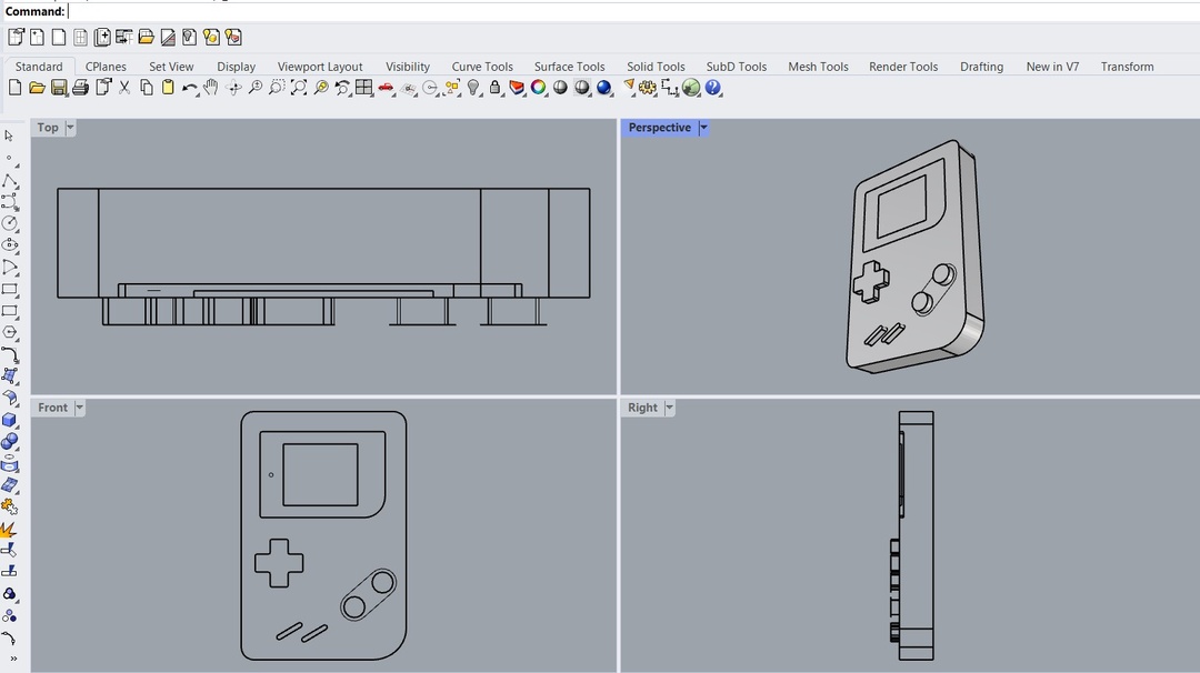
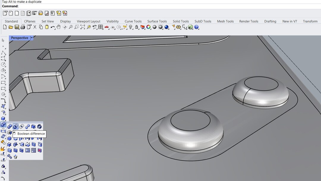
Now i wanted a depression on the surface of the mainbody , on the capsule shape ,where the round buttons
sit.There are many ways to do this but i thought of making use of the boolean difference command.Boolean
Difference command subtracts the geometry of one object from another object.
To do this first i made a extrusion body of the capsule inside the main body extrusion. Then click on boolean
difference icon or type it in the command bar and enter. click on the main body from which i need to subtract and
click on the spacebar.
Then click on the capsule extrusion and click enter.
I added fillets to the sharp edges where the cut occured.
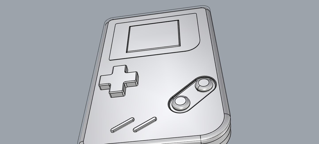
Now with most of the solid operations complete i can move on the rendering of the objetcs.
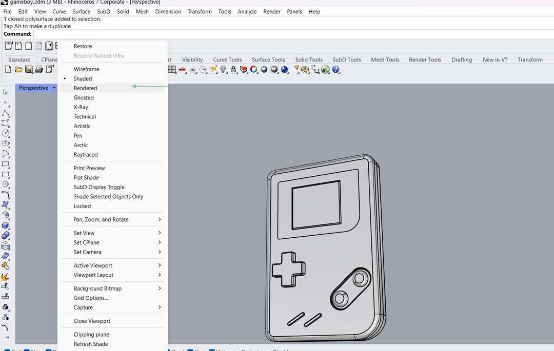
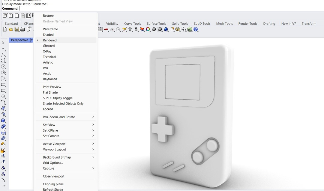
To view the real time rendered view in the viewport click on the dropdown of the viewport and choose
"render".
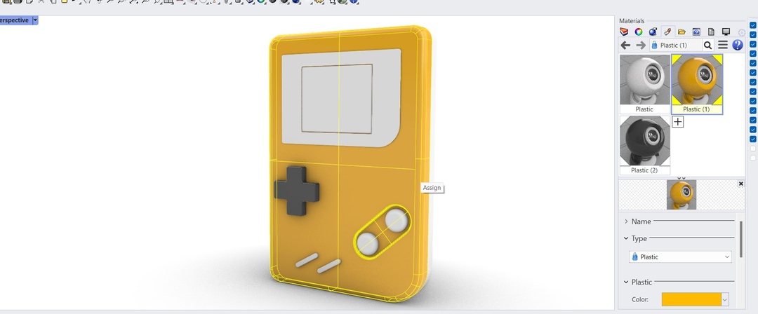
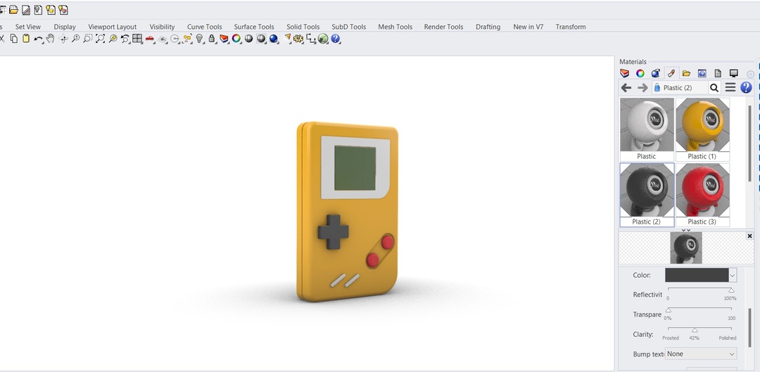
You can assign materials and textures to the solids to add visual detail and realism to the renders. Materials
can be added to a whole layer if you are working in layers or it can be assigned to individual objects too.
To assign a material to individual objects, select the body and go to the edit menu. Click on the the Materials
List, on the Library tab or the Material Editor tab, and then drag a material onto the body. You can choose a new
material by clicking og the '+' icon and choose the required material. You can edit or modify the material
properties by double clicking the material or in the collapsable tabs underneath(type,name,etc) .
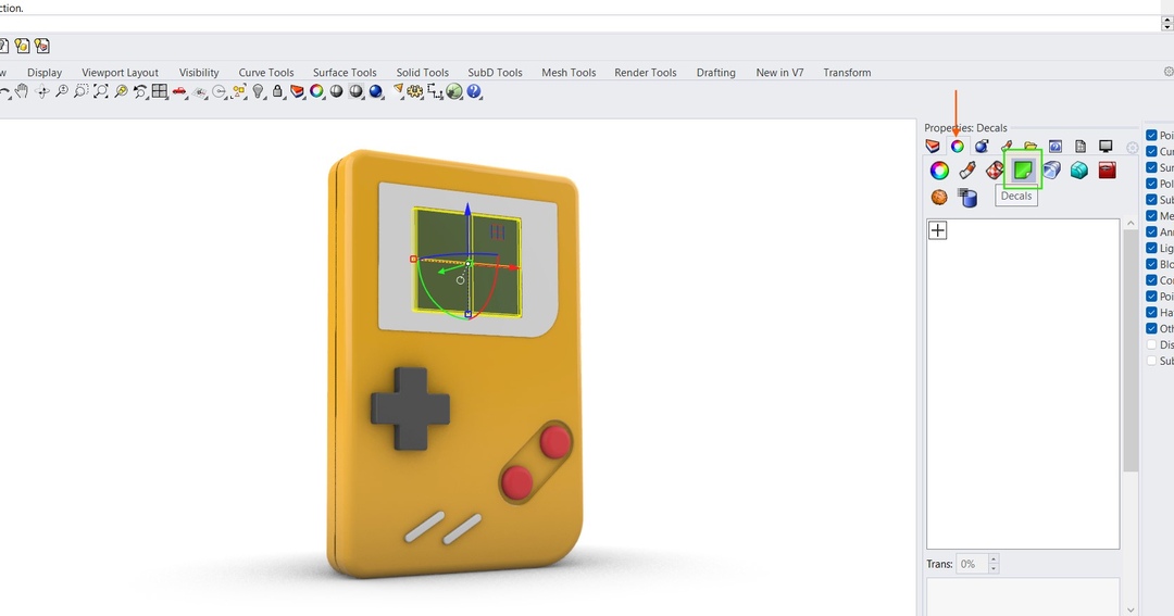
Next i wanted to add an decal to the screen of the console. Under the Properties panel , Select the Material tab. You can find the Decal icon here.. Click on the Add button to make the decal.
elect the image you want to use as your decal. Once the image appears on the surface, you can position it on the surface properly. You can modify the properties of the decal such as the transparency, brightness, and repeat options.
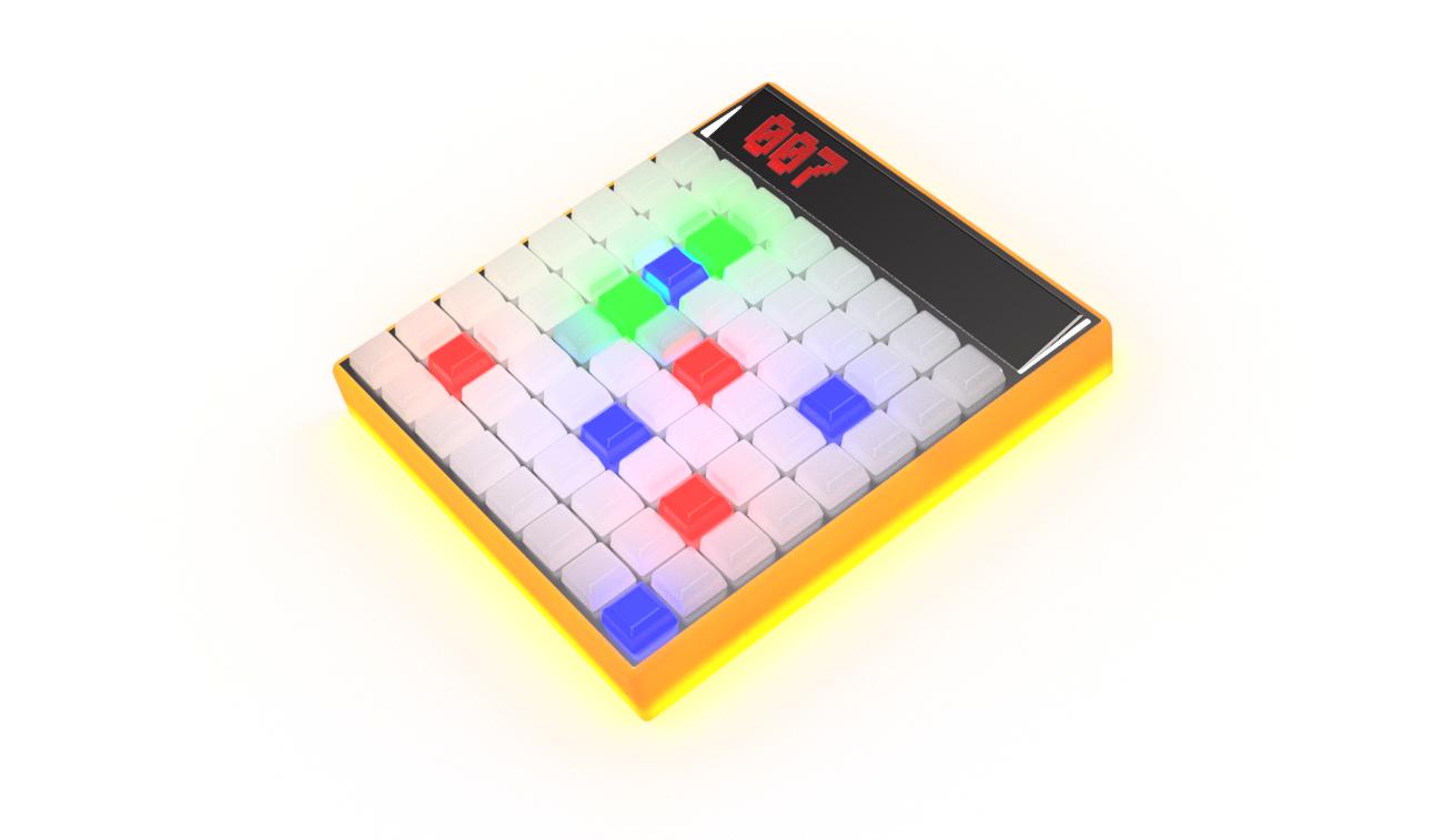
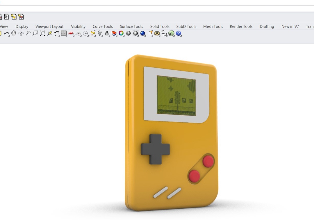
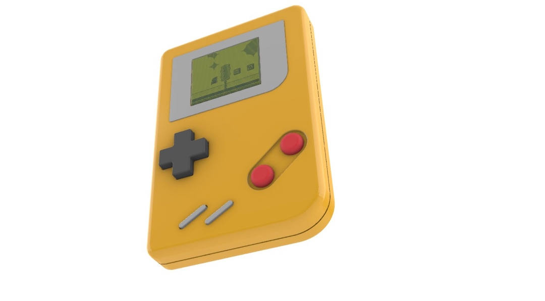
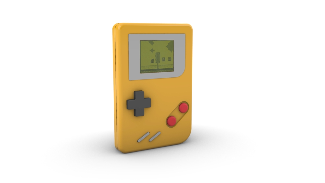
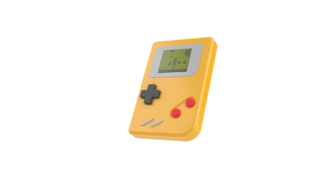
The rendered view of the game console lookes like this.
You can view a more deatailed render using the raytrace option . You can find this view under the dropdown in the viewport.
Animating the 3D model
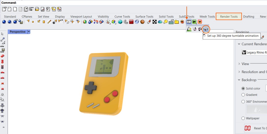
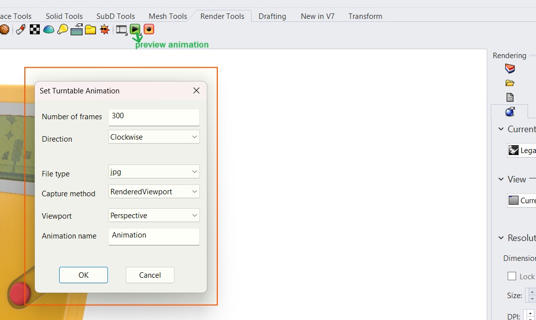
I decided to do a simple turntable animation in rhino for the the gameboy model that I made.The animation toolbar provides tools for creating animated views in Rhino.
Choose among the viewport display and render modes to display the animation images.
Go to the the render tools tab >> Under animation Setup i chose turntable.Turntable gives a rotated a view around the target. Here a dialogue box appears where you can select the number of frames and the view mode of the animation.
click on the PlayAnimation command which will play the animation.
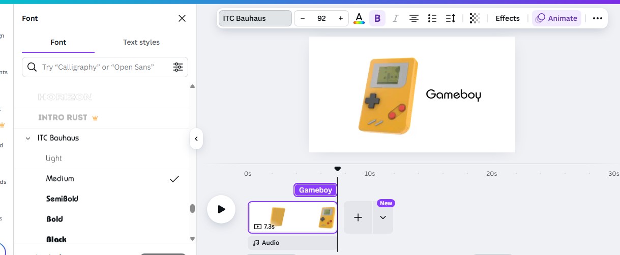
Just for an added effect I made a text animation to accompany the video in canva.
Image and Video Resizer
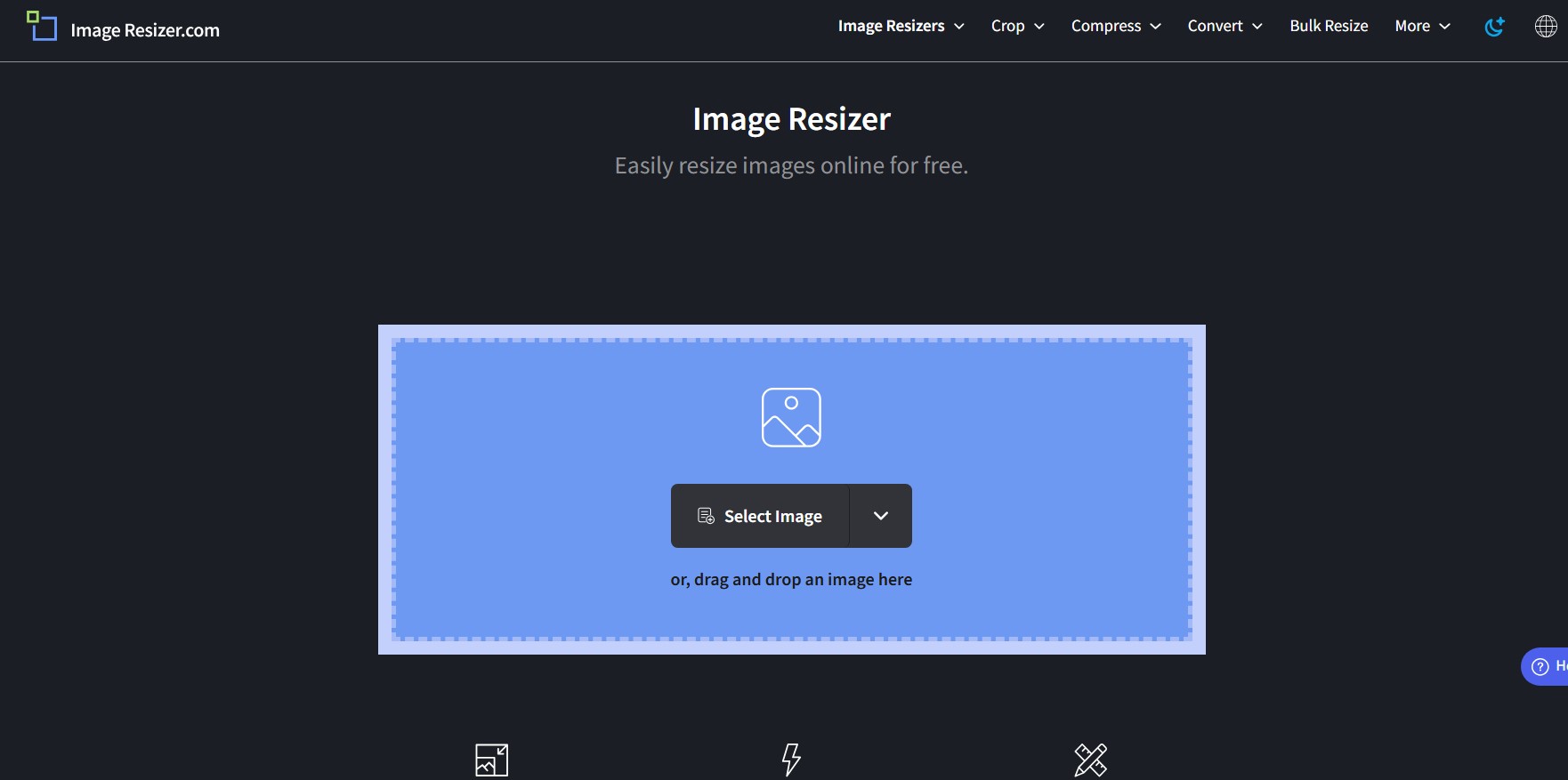
Image Resizer
I used Image Resizer to resize the images as some were too big to be pushed into the repository.
Image Resizer is a cloud-hosted, highly scalable tool that can resize
images
fast.
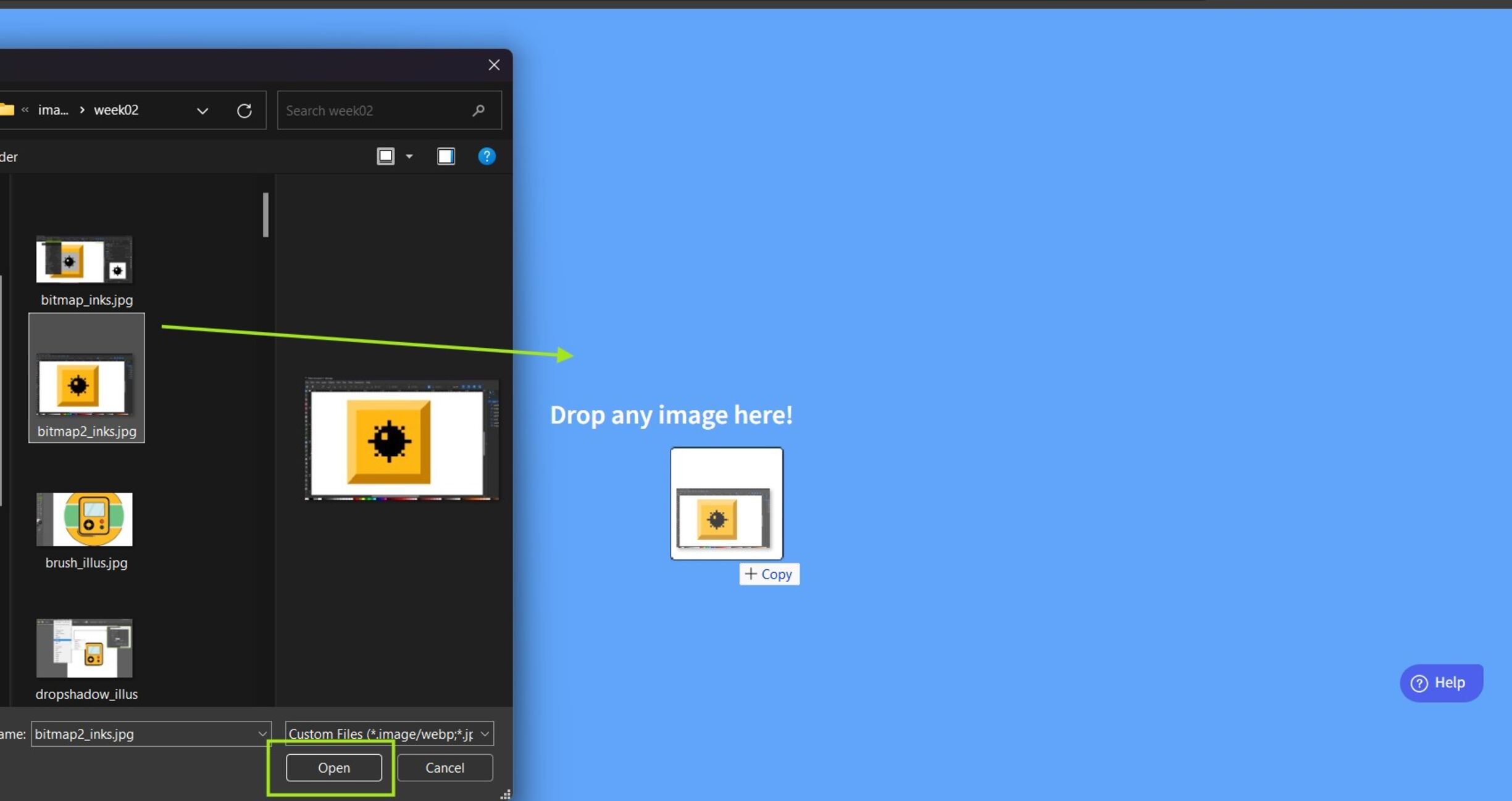
Open Image resizer in your browser. There are options to either rez=size a single image or in bulk. As i had
many images to resize i chose the bulk resize option.
Then you can drag and drop the files or open from your computer
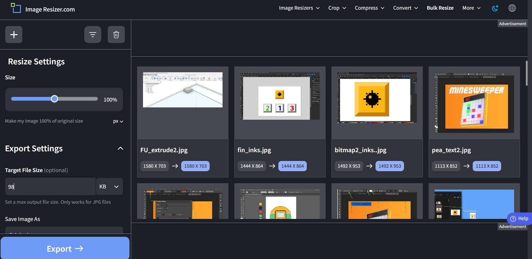
Once the images are loaded the appliction takes you to a screen where you can set how much the images should be
compressed. Adjust according to requirements
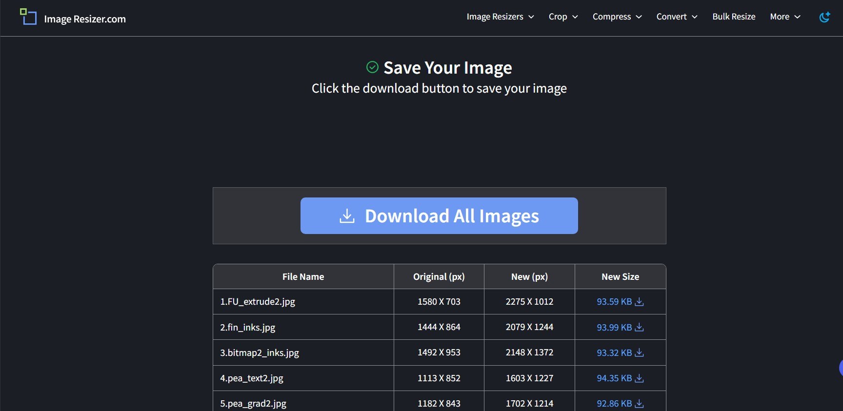
Click Export. The appliction starts the processing. Once the images are ready you can download them.
Video Resizer
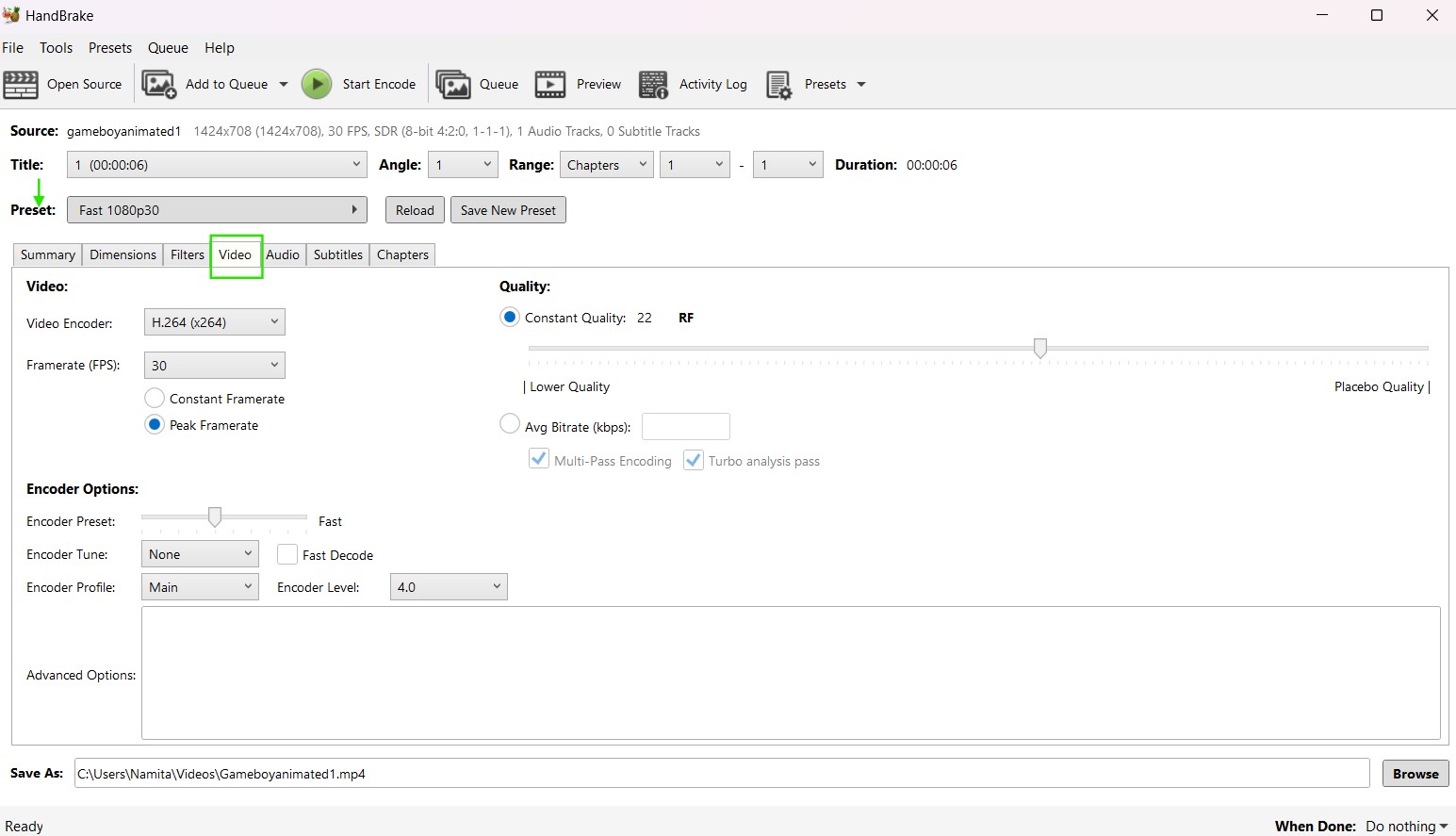
The tool i am using for compressing videos is Handbrake.
HandBrake is a open-source tool for converting video from nearly any format to a selection of widely supported codecs.
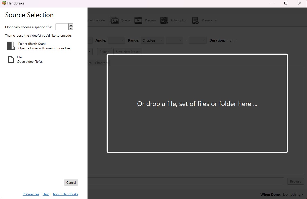
Install Handbrake to your computer
Launch the software. Click on open source to choose the video ypu need to encode or just drag and drop the video to the interface.
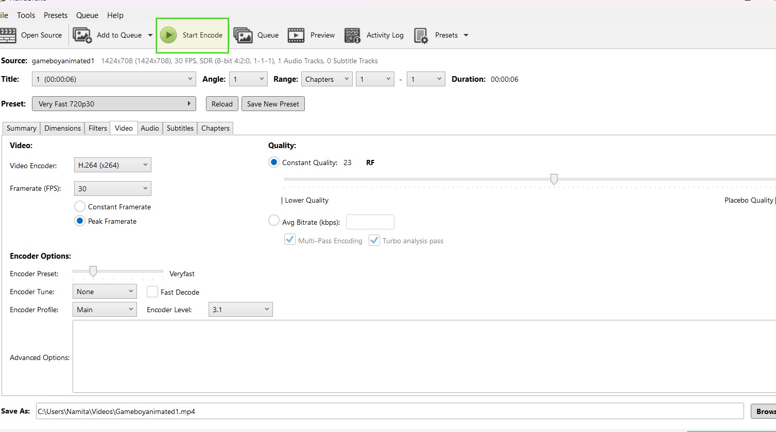
Under the videos tab you can choose the preset that you would want the video to be in. You can also set custom frame rate to compress the video further.
Once the settings are done click on 'Start Encode'
The compressed video will be saved to the folder selected.